
Quick answer: what makes an aluminum enclosure or frame suitable for medical equipment?
An aluminum medical-equipment enclosure or frame must maintain functional alignment, protect users from accessible hazards, support cooling and electrical bonding, tolerate its intended cleaning process and allow controlled assembly and service. Suitability is demonstrated by the completed device’s risk management and verification evidence, not by the metal alone.
Begin with intended use, users, patient and operator proximity, equipment classification, applied loads, mobility, environmental conditions, cleaning or reprocessing instructions, electrical architecture and applicable standards. Then design structural datums, panels, joints, seals, ventilation, handles and service access around those inputs.
The supplier drawing should distinguish critical interfaces, cosmetic zones and ordinary clearances. Validate the production-equivalent assembly with installed electronics, accessories, cables and cooling hardware. A precise empty frame cannot establish device safety, EMC, usability, cleanability or regulatory compliance.
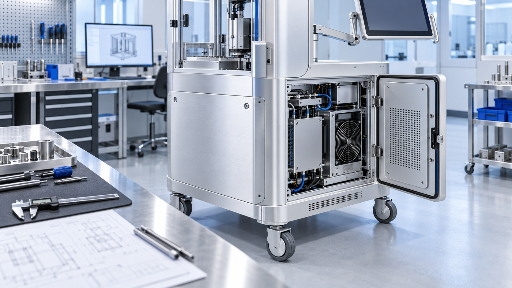
Translate intended use into mechanical requirements
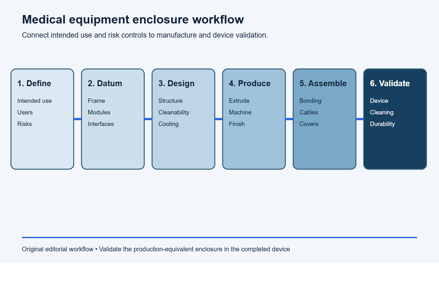
Use this sequence before choosing extrusion, plate or finish:
- Define intended use and enclosure boundary. Record users, patient/operator proximity, environment, mobility, accessories and service tasks.
- Flow risks into measurable controls. Identify structural, electrical, thermal, cleaning, ingress, sharp-edge and handling requirements.
- Map functional datums and interfaces. Connect frames, panels, electronics, displays, doors, wheels, grounding and cooling hardware.
- Select materials and processes. Assign extrusion, machined plate, formed sheet, joints and finishes according to function and production volume.
- Validate the production-equivalent device. Test alignment, stability, cleaning, cooling, bonding and service behavior with installed equipment.
“Medical equipment” spans laboratory analyzers, imaging accessories, diagnostic carts, rehabilitation systems and patient-monitoring hardware. Their risks and environments differ. Define where the enclosure is used, who touches it, whether it moves, what liquids or disinfectants may contact it and which failures could affect a patient, operator or result.
ISO 14971:2019 describes a life-cycle process for medical-device risk management. Use the manufacturer’s risk analysis to connect mechanical hazards and essential functions to design inputs, controls and verification. BAOSONG can manufacture controlled parts, but the legal manufacturer remains responsible for device classification, regulatory strategy and compliance.
The FDA’s design-control overview describes design inputs, interfaces, verification, validation and change control. Freeze enclosure interfaces by revision and record why critical tolerances, materials and finishes exist so later changes can be assessed against risk.
Create an enclosure input matrix
| Input | Define | Mechanical implication |
|---|---|---|
| Use environment | Clinical, laboratory, home, transport, temperature, humidity and liquids | Seals, corrosion system, vents and handling |
| People interface | Patient, operator, service access, touch points and foreseeable misuse | Edges, stability, pinch protection and access panels |
| Function | Sensors, optics, motion, pumps, electronics and thermal limits | Datums, stiffness, vibration and cooling |
| Cleaning | Agents, concentration, contact time, method and cycle count | Materials, finish, seams and drainage |
| Electrical | Protective earth, insulation, leakage-current architecture and EMC | Bonding points, barriers, apertures and cable entries |
| Production | Quantity, assembly sequence, inspection and traceability | Process route, fixtures, joining and records |
Design the frame around functional datums
A medical frame may locate optics, motors, sample paths, imaging components or articulated arms. Trace the datum chain from the floor or table through the structure to each functional component. Use stable machined interfaces where alignment matters and allow clearance elsewhere.
Separate strength from stiffness. A frame can remain below yield yet deflect enough to disturb calibration, sealing or motion accuracy. Include panel openings, joints, caster compliance and installed component masses in analysis. Check static loads, transport shock, fan or pump vibration and forces from doors, drawers, cables and user handling.
Use ASME Y14.5-2018 (R2024) if the drawing invokes that GD&T system. BAOSONG’s guide to practical aluminum machining tolerances helps distinguish alignment features from broad cosmetic surfaces. Define the inspection support and assembly state for large frames.
Choose extrusion, machined plate and formed panels by function
Extrusions suit rails, columns, channels, equipment bases and repeated edges. They can integrate grooves, gasket lands, cable paths and mounting features. Machined plate supports local precision, optics or motion hardware. Formed sheet and thin plate efficiently cover broad surfaces and create removable service panels.
A hybrid design often provides the best balance: extruded load paths, CNC-machined datum brackets and formed covers. Review BAOSONG’s custom aluminum extrusion design guide, profile manufacturability guide and extrusion plus CNC machining guide before tooling.
Minimize unnecessary part count while preserving access to items that need inspection or replacement. Integrated screw bosses and channels can simplify assembly, but inaccessible crevices or hidden fasteners may hinder cleaning and service. Evaluate the full use and maintenance sequence.
Design mobile equipment for stability and handling
For carts and mobile systems, establish the center of gravity in every permitted configuration, including raised displays, extended drawers and attached accessories. Check tipping over thresholds, ramps and foreseeable user forces. The caster and handle arrangement should guide motion without making cables or covers carry unintended loads.
Provide strong, accessible lifting or pushing points and protect fingers around moving panels. Brake selection, wheel diameter and base geometry belong to the completed device design. Validate the loaded system on representative floors and transitions rather than evaluating the aluminum base alone.
Make cleaning requirements measurable
Different equipment may require routine wipe-down, disinfection or validated reprocessing. Specify the actual agents, concentrations, temperatures, contact times, application method and number of cycles. “Medical grade finish” is not a complete requirement.
The FDA identifies hinges, adjacent surfaces, O-rings, valves and inaccessible features as places that can retain debris in reusable devices. Its reprocessing design guidance emphasizes smooth, accessible geometry and validation of cleaning instructions. Apply that evidence according to the actual device and patient-contact context.
Use radiused transitions, accessible seams and drainage where liquids are expected. Avoid exposed threads and deep pockets in cleaning zones. Design removable panels so users can reinstall them correctly without trapping cables, folding seals or leaving contaminated gaps.
Select finish for chemistry, wear and appearance
Anodizing can provide a durable aluminum surface, while conversion coating, powder coating or other systems may better fit bonding or appearance needs. Test the selected finish against the specified cleaners and cycle count. Inspect for discoloration, chalking, corrosion, gloss change, adhesion loss and degradation of markings or seals.
Mask electrical bonding lands, precision fits and thermal interfaces as required. BAOSONG’s surface-finishing overview and anodizing page support process review. Establish approved appearance samples and viewing conditions for premium visible surfaces rather than relying on color names alone.
Coordinate cooling, noise and cleanability
Electronics, power supplies, lamps, motors and embedded computers generate heat. Map the sources and allowable component temperatures, then define inlet air, exhaust path, fan curve and degraded mode. Prevent cables and replaceable filters from creating unplanned bypass or recirculation.
Vent perforations affect airflow, liquid ingress, cleaning access, acoustics and EMC. Design these functions together. For systems using conductive or liquid cooling, define cold plates, interfaces, hoses, leak detection and condensation controls within the complete risk analysis.
Measure sound and vibration in the operating modes relevant to users. Structural panels can radiate fan or pump vibration even when temperatures are acceptable. Use stiffening, isolation or control changes based on measured paths, then confirm that changes do not compromise cleaning or electrical bonding.
Plan bonding, EMC and cable routing at every joint
Aluminum enclosures can support shielding and protective bonding only when seams, coatings, fasteners and cable penetrations are engineered. Anodized surfaces are electrically insulating. Define bare contact lands, bonding hardware, conductive gaskets and inspection points where the electrical design requires them.
Separate mains, high-current switching, sensitive signals and moving cables. Protect bend radius and strain relief through the full service motion. A panel or frame supplier cannot certify EMC; test the assembled device with production-equivalent electronics, software, cables, covers and accessories.
Design doors, covers and service access for repeatable assembly
| Feature | Control | Verify |
|---|---|---|
| Door or cover | Positive location, captive hardware, opening force and interlock interface | Fit, cycle, misuse and service test |
| Gasket | Land geometry, compression, corners and chemical compatibility | Gap map, ingress and cleaning cycles |
| Bond | Masked land, hardware, surface preparation and torque | Resistance before and after durability |
| Cable | Separation, bend radius, strain relief and abrasion protection | Routing in every allowed position |
| Cosmetic panel | Surface class, grain direction, rack marks and protective packaging | Approved sample and final inspection |
Validate the assembled medical equipment
Start with material and dimensional evidence, then build representative assemblies. Verify structural alignment, stability, mobility, ingress where required, cooling, acoustic behavior, grounding interfaces, service access and cosmetic acceptance. Repeat relevant checks after cleaning, environmental and mechanical durability cycles.
Use worst-case configurations identified by risk analysis. The FDA’s current reprocessing guidance recommends that reusable devices be designed for adequate cleaning and that reprocessing instructions be validated. Record the exact agents, soils, cycles, disassembly and acceptance method when applicable.
Retain measurement setup and uncertainty with inspection results. NIST’s discussion of dimensional calibration uncertainty supports defensible acceptance decisions for critical frame and enclosure interfaces.
Protect cosmetic and functional surfaces through delivery
Premium medical equipment often places functional precision and visible appearance on the same assembly. Identify Class A surfaces, machined datum faces, gasket lands, bonding contacts and optical mounting zones in the manufacturing plan. Use dedicated handling fixtures and clean gloves after final finishing where the approved appearance requires them.
Packaging should restrain the frame at strong structural locations without loading doors, covers, display arms or machined edges. Separate finished aluminum surfaces from abrasive foam, loose hardware and dissimilar-metal debris. If protective film is permitted, verify that its adhesive removes cleanly after the expected storage duration and temperature exposure.
Define incoming inspection around the risks of final assembly. A small scratch may be cosmetic on a hidden internal rail but unacceptable on a front panel; a mark on a gasket land or bonding contact may be functionally important. Photograph approved appearance standards and keep them under revision control. After simulated transport, repeat key alignment, door operation, caster, bonding and cosmetic checks so packaging performance is connected to device integration.
Use first-article evidence to control production changes
A first article should record material certificates, process route, dimensional results, finish samples, joint condition and assembly findings against one drawing revision. Link deviations to a disposition and preserve the measurement method. For recurring production, define sampling around process risk and capability rather than inspecting every noncritical dimension at the same frequency.
Changes to extrusion dies, machining fixtures, coating suppliers, cleaners, gaskets or assembly torque can alter device performance. Route these changes through the medical-device manufacturer’s change process before implementation. Repeat the verification affected by the change, and retain traceability between approved parts, process records and delivered lots.
RFQ checklist for medical equipment enclosures and frames
Paste this scope into the RFQ and attach the controlled enclosure model, component drawings, interface documents and verification matrix.
RFQ scope: Please quote [enclosure/frame revision] for [prototype quantity] and [annual volume]. The component supports [device modules and loads], operates in [environment], is cleaned with [agents, method and cycle count], and includes [cooling, bonding, sealing and service interfaces]. Quote the proposed aluminum alloys, component split, manufacturing, joining, finish, tooling, unit price, lead time and capacity. List every assumption and deviation.
Required evidence: Provide material traceability, dimensional and cosmetic inspection, joining and finish records, cleaning-compatibility evidence required by the drawing, bonding checks, first-article documentation, protected packaging and change-notification triggers. Identify electrical, EMC, usability, biocompatibility and device-level regulatory validation outside the supplier scope.
- Device intended use, environment, users and enclosure boundary.
- Controlled 3D model and 2D drawings with functional datums.
- Installed masses, mobility, handling, shock and vibration cases.
- Critical alignment, sealing, cooling and electrical-bonding interfaces.
- Cleaning agents, method, contact time and required cycle count.
- Alloy, temper, product form, joining and finish requirements.
- Cosmetic zones, approved samples, masking and allowed contact marks.
- Assembly sequence, captive hardware, cable routing and service access.
- Inspection methods, traceability and device-level validation plan.
- Prototype and production quantities plus change-control expectations.
Stop conditions: the medical equipment enclosure is not ready for release
Pause tooling or production release if any condition below remains unresolved.
- intended use, users, patient/operator proximity or enclosure boundary is unclear;
- installed mass, mobile stability, handling, shock or vibration cases are missing;
- functional datums do not connect critical device modules and service interfaces;
- cleaning agent, concentration, contact time, temperature or cycle count is undefined;
- cooling openings, noise, cleanability and ingress requirements conflict;
- bonding lands, coatings, cable routes or electrical isolation are unresolved;
- cosmetic zones, approved samples, masking or protected packaging are unspecified;
- component inspection is being treated as proof of complete medical-device compliance.
Frequently asked questions
Is anodized aluminum suitable for medical equipment?
It can be suitable for many nonpatient-contact housings and frames when the alloy, anodize specification, cleaning chemicals, wear and electrical interfaces are validated. Suitability depends on intended use and the complete device.
Does a precision frame make the medical device compliant?
No. It can support alignment and repeatable assembly, but compliance belongs to the finished device under its applicable risk management, electrical, EMC, usability, cleaning and regulatory requirements.
Should medical equipment use extrusions or machined plates?
Many designs use both. Extrusions suit repeated structural rails and channels; machined plates suit local datums and complex interfaces; formed panels cover broad surfaces. Choose by function and total assembly evidence.
How should cosmetic quality be specified?
Define visible zones, finish, texture or grain direction, color range, viewing conditions, allowable defects and an approved sample. Also specify handling and packaging so the accepted surface reaches final assembly intact.
Request a medical-equipment manufacturing review
BAOSONG supports aluminum extrusion, CNC machining and finishing for controlled industrial components. Send the device-level enclosure requirements, drawings, load cases, cleaning and bonding interfaces, inspection plan and quantities through the contact page for manufacturability and quotation review.
Recommended Downloads for Aluminum Surface Finish Control
Use these BAOSONG references to select a finish, define cosmetic acceptance and prepare a production-ready requirement.
- Aluminum Surface Finish Selection Guide (PDF)
- Anodizing Guide: Color, Masking & Cosmetic Standards (PDF)
- Powder Coating, Brushing & Polishing Guide (PDF)
- Surface Finish Comparison Chart (editable Excel)
- Cosmetic Surface Requirement Template (editable Excel)
- Appearance Requirement Template (editable Excel)
Need help matching color, masking, gloss or cosmetic zones to your drawing? Contact BAOSONG engineering support.
