
Quick answer: how should engineers design a custom aluminum extrusion?
A successful custom aluminum extrusion design starts with the functions that must run continuously along the part: load paths, enclosure walls, heat-transfer fins, cable channels, fastening features and locating surfaces. Convert those functions into a balanced cross-section, then review whether the profile can flow through a die, remain stable during cooling and straightening, accept the required finish, and provide usable datums for cutting, drilling or milling.
Do not assign one tight tolerance to the entire profile. Separate extrusion-controlled characteristics—such as wall thickness, cross-sectional metal and space dimensions, twist, straightness and flatness—from features that will be created later by CNC machining. Identify the characteristics that control assembly and inspection, and agree on their measurement method before the die is released.
The best result comes from a joint design review between the product engineer, extrusion supplier, machining team, finisher and quality team. Small changes to wall balance, tongue depth, radii, datum pads or machining allowance can make the profile easier to produce while preserving its function. BAOSONG’s custom aluminum extrusion service provides a starting point for discussing that manufacturing route.
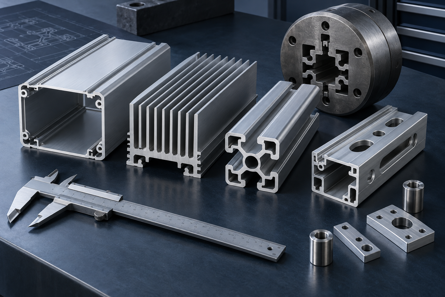
Use this guide before releasing the extrusion die
- Mark the functions: identify loads, interfaces, heat paths, fasteners, seals, cosmetic zones and keep-out areas.
- Assign each feature: decide which geometry should run continuously in the extrusion and which local precision belongs to CNC machining.
- Review the whole route: confirm alloy, temper, die feasibility, tolerances, cut-off, machining, finishing and inspection with the responsible suppliers.
- Close the release gate: approve one controlled model and drawing, record open risks and release tooling only when acceptance methods are agreed.
Turn product functions into an extrusion cross-section
Begin with interfaces and load paths rather than drawing a detailed profile immediately. Mark the envelope, mating components, keep-out zones, heat sources, cable routes, seals, fasteners and surfaces that users will see. Then decide which features benefit from being continuous along the extrusion length. A continuous rib, groove, rail or enclosure wall is usually a natural extrusion feature. An isolated pocket, transverse hole or local boss generally belongs to a secondary operation.
| Design decision | Effect on extrusion | Question to resolve |
|---|---|---|
| Overall envelope | Influences press and tooling options through profile size and weight per length | Can the section be made smaller, split, or assembled without harming function? |
| Continuous walls, ribs and channels | Can consolidate parts and reduce later machining | Does every continuous feature earn its material and tooling complexity? |
| Hollow or semi-hollow geometry | Changes die design, metal flow and feasible tolerances | Is the enclosed space essential, or can an open profile plus cover perform the same job? |
| Critical mating features | May require datum strategy, controlled extrusion dimensions or CNC finishing | Which characteristic actually controls fit, sealing or alignment? |
| Cosmetic faces | Affects die-line acceptance, handling, finishing and packaging | Where are appearance limits needed, and how will they be inspected? |
The Aluminum Extruders Council describes profile size using the circumscribing circle diameter and notes that shape, profile weight and available press capacity affect economics. Its key design considerations also emphasize balanced walls, symmetry where practical, and avoiding deep, narrow tongue features. These are design-review inputs, not universal pass/fail limits; the selected extruder must evaluate the actual alloy, temper, section and order quantity.
Choose alloy and temper from the complete process route
Alloy selection has to account for extrudability, strength, corrosion exposure, surface finish, joining and secondary machining. 6063 is often considered for profiles where extrudability and anodized appearance matter, while 6061 is often considered where higher structural properties or machining requirements carry more weight. Neither is automatically correct. Section complexity, temper, mechanical-property requirements and finish specification can change the choice.
Temper is part of the material definition. T5 and T6 represent different thermal histories and property routes; T651 adds stress relief by stretching to solution heat treatment and artificial aging. Use the required governing material specification and verify what product forms and tempers are available. BAOSONG’s guide to aluminum tempers T5, T6 and T651 explains the terminology, while the Aluminum Association maintains the industry’s alloy and temper designation systems.
Keep wall thickness transitions gradual and purposeful
Balanced wall thickness supports more uniform metal flow and cooling. Abrupt changes create regions that resist flow differently and may contribute to dimensional variation, surface effects or distortion. Use gradual transitions, radii and tapers where the function allows. Remove material that serves no structural, thermal, fastening or finishing purpose, but do not thin a wall from a generic online rule.
There is no single minimum wall thickness suitable for every custom extrusion. Feasibility depends on alloy, temper, profile size, wall length, shape complexity, die support, press capability and order economics. Mark the walls that are function-driven and allow the extrusion supplier to recommend changes to noncritical areas.
Review hollows, tongues and deep channels early
A solid profile contains no completely enclosed void. A hollow profile does, while semi-hollow classification depends on the geometry of a partially enclosed space and the applicable industry definition. These categories matter because the die construction and tolerance tables can differ. Do not classify a section from appearance alone; have the extruder confirm the category used for tooling and quotation.
Deep narrow channels and tall thin fins create slender die features commonly called tongues. Increasing depth while reducing opening width makes support and metal flow more difficult. If a channel is challenging, consider a wider opening, shorter depth, more generous root radius, changed orientation, or a two-piece assembly. For heat sinks, fin geometry also has to satisfy airflow and thermal analysis, so extrusion feasibility should be reviewed alongside thermal performance.
Use ribs, screw ports, grooves and bosses with a clear function
Extrusion can place continuous features exactly where they support assembly:
- Ribs and webs can improve bending or local panel stiffness, but their location and thickness affect flow balance.
- Screw ports can support end-fastened assemblies when their geometry, fastener engagement and edge conditions are validated.
- T-slots and grooves can locate accessories or capture hardware, but the opening and internal space need separate dimensional review.
- Bosses and datum pads can provide material for drilling, tapping or milling after extrusion.
- Snap and hinge concepts need tolerance-stack, fatigue, assembly-force and service-life validation.
Avoid forcing every detail into the die. Features that occur only once, vary between product versions, or require precise relationships to a cut end are often more robust as secondary machining operations.
Add radii and symmetry where function permits
Sharp internal transitions concentrate stress and make smooth metal flow harder. Practical internal and external radii reduce abrupt section changes and can improve die durability. The exact radius should be reviewed against profile size, wall thickness, cosmetic requirements and mating geometry.
Symmetry can help distribute metal and thermal contraction more evenly. When the product cannot be symmetric, aim for balanced material distribution and identify the side that controls assembly. The extruder may use die correction and process controls for an asymmetric section, but the engineering drawing should still distinguish functional requirements from nominal CAD perfection.
Specify extrusion tolerances by category
Extrusion tolerances are not interchangeable with machined-part tolerances. The Aluminum Association’s extrusion tolerance guidance separates topics including twist, straightness, flatness and metal-versus-space dimensions for solid and hollow profiles. Its historical selected tolerance tables are useful for understanding the structure of the standards, but the drawing and purchase order should cite the agreed current standard and edition.
| Tolerance category | Why it matters | Design response |
|---|---|---|
| Metal dimension | Controls a dimension through solid material | Identify whether thickness is functional, cosmetic or only nominal |
| Space dimension | Controls an opening, channel or internal clearance | Check fit at the actual mating envelope, including finish buildup |
| Flatness | Affects panel contact, sealing and appearance across a face | Define the functional area and inspection span |
| Straightness | Affects rails, long assemblies and machining setup | State the evaluation length and downstream straightening assumptions |
| Twist | Changes the orientation of faces along the length | Define the length and the faces used to evaluate rotation |
| Cut length and squareness | Affects stack-up and end-mounted components | Specify saw-cut acceptance or machine the end when required |
Tighter values should be justified by fit, sealing, optics, motion or another measurable function. A blanket tight tolerance can add straightening, sorting, machining and inspection without improving the assembly.
Build the datum and inspection plan before tooling release
Choose datums from stable, accessible surfaces that represent how the profile locates in the product. A narrow fin, flexible lip or uncontrolled cosmetic edge is rarely a good primary datum. When a profile will be machined, add robust locating pads or rails and make sure the fixture can reach them without excessive clamping distortion.
Use drawing language that supports one interpretation. ASME Y14.5 establishes rules for communicating dimensions, datums and geometric tolerances. The chosen drawing standard must be stated on the product definition. Define how long-profile form is measured, the condition of the part, the support method, inspection temperature where relevant, sampling and the reporting format. NIST’s dimensional metrology guidance explains the role of traceable length measurement and calibration; the project’s actual inspection system still needs a suitable uncertainty for the tolerance being verified.
Plan cut-off and secondary CNC machining together
Extrusion creates a continuous profile; the finished component may still need cut-off, end facing, drilling, tapping, pocketing or localized sealing surfaces. Leave enough stock where machining will establish a precise feature, and ensure the stock remains available across the expected extrusion variation. Do not assume the nominal CAD surface will always lie in the same place relative to a machined datum.
Locate cross-holes and end features from functional machined datums when their relationship is critical. For long or thin sections, review clamping force, access, chip evacuation and setup transfer. See BAOSONG’s aluminum CNC milling service and practical aluminum CNC tolerance guide when deciding which features should be finished after extrusion.
Account for anodizing and cosmetic requirements
Surface finish is a design input. Anodizing changes appearance and adds an oxide layer, so fits, electrical contact, grounding points, threaded features, masking and sealing surfaces need review. Color and gloss can vary with alloy, temper, surface preparation, geometry, lot and viewing conditions. Define cosmetic zones, allowed process marks and comparison conditions instead of asking for an undefined “perfect” surface.
For visible products, agree on die-line acceptance, handling protection, rack or contact areas, color standard, gloss method and lot-to-lot expectations. BAOSONG’s anodized aluminum overview and surface-finishing services help organize those questions.
Design joints and assemblies around real variation
A profile rarely works alone. Model the tolerance stack with mating components, finish thickness, fastener clearance, seal compression and thermal expansion. Sliding fits need clearance over the full engaged length. End-fastened screw ports need validated engagement and access. Covers and snap features need assembly-force and removal testing. Welded structures need allowance for heat distortion and post-weld requirements.
Prototype the interfaces that carry the greatest functional risk. A short sample can confirm local fit and appearance, while full-length samples may be needed to evaluate straightness, twist, handling and assembly over distance.
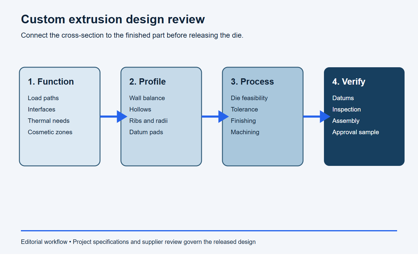
Use a four-stage design review
- Function review: confirm loads, interfaces, thermal needs, environmental exposure, service access and cosmetic zones.
- Profile review: confirm envelope, alloy and temper, wall balance, hollows, tongues, ribs, radii, joints and weight per length.
- Process review: confirm die concept, press fit, expected tolerance categories, straightening, cut-off, finishing, machining and handling.
- Verification review: confirm datums, measurement methods, gauges, sampling, appearance standards and approval samples.
Record open decisions and assign owners. The extrusion supplier should approve manufacturability assumptions; the design authority should approve functional changes. Tooling release is the point where vague requirements become expensive, so close the critical questions first.
Stop conditions: do not release the extrusion die yet
- The model and drawing do not agree on profile geometry, revision, alloy, temper or finish.
- A critical mating dimension has no declared datum, tolerance category or practical inspection method.
- Hollow classification, tongue support, wall balance or press suitability has not been reviewed by the selected extruder.
- Machining allowance is based on the nominal profile without considering extrusion variation and fixture location.
- Cosmetic zones, anodizing expectations, rack locations or packaging protection remain subjective.
Copy-ready custom extrusion RFQ request
Paste this request into the RFQ and replace the brackets:
Please review custom profile [part number/revision] for [application and annual quantity]. The critical functions are [loads, fits, seals, thermal paths and appearance zones]. Quote alloy/temper [requirement], tooling, sample quantity, production quantity, cut length, secondary machining, finish, inspection and packaging separately. Confirm the profile classification, press and die assumptions, proposed tolerance standard, datum strategy, machining allowance and measurement method for each critical characteristic. Identify every requested change before die release and state what sample or first-article evidence will be supplied.
What should be included in a custom extrusion RFQ?
A useful RFQ lets the supplier assess the whole production route rather than quote a shape in isolation. Include:
- 3D model and controlled 2D drawing with revision;
- alloy, temper and applicable material specification;
- profile length, finished cut length and annual or batch quantity;
- critical-to-function characteristics and their acceptance criteria;
- datum scheme, general tolerance standard and specific geometric controls;
- surface finish, cosmetic zones, color standard and masking needs;
- secondary machining, deburring, cleaning and assembly requirements;
- inspection reports, traceability, packaging and labeling needs;
- mating-part information or interface drawings where fit is critical.
For a project-specific review, send BAOSONG’s engineering support team the controlled files and expected volume. The team can discuss extrusion, machining and finishing as one manufacturing route without treating any unreviewed tolerance or feature as a guaranteed capability. You can also contact BAOSONG with the application and acceptance requirements.
Frequently asked questions
What information is needed before designing an extrusion die?
Provide the controlled profile drawing and model, alloy and temper, tolerance standard, critical features, order quantity, length, finish, secondary operations and inspection requirements. Mating interfaces and cosmetic zones should be identified before tooling release.
Should every precise feature be extruded into the profile?
No. Continuous features that tolerate normal extrusion variation are good candidates. Local holes, pockets, end relationships and high-precision interfaces may be better created by CNC machining. Compare total process cost and capability rather than feature count alone.
How can an engineer reduce custom extrusion cost?
Use a compact envelope, balanced walls, practical radii, fewer difficult hollows or deep tongues, function-based tolerances and continuous features that replace separate components. Confirm press and die feasibility before freezing the section.
Can a prototype die guarantee production results?
A sample run provides evidence for the reviewed configuration, but production acceptance still depends on the released drawing, approved process, lot controls and inspection plan. Validate full-length form, finish and downstream operations when they affect function.
Recommended Downloads for Aluminum Extrusion Design
Use these BAOSONG references to set profile geometry, wall thickness, tolerances and downstream CNC features before releasing an extrusion design.
- Custom Aluminum Extrusion Design Guide (PDF)
- Wall Thickness and Tolerance Guide (PDF)
- CNC Machining Guide for Aluminum Extrusions (PDF)
- Aluminum Alloy Comparison Chart (editable Excel)
Need help checking an extrusion profile or manufacturability risk? Contact BAOSONG Precision.
