
Quick answer: custom aluminum solar inverter heat sinks
BAOSONG manufactures custom aluminum solar inverter heat sinks for the device layout and cooling air available in the installed equipment. We recommend an extruded base and fins with locally machined contact pads when that construction meets the heat-sink target. If a device stays hot, we first separate a contact or heat-spreading problem from an airflow problem before changing the fin route.
Aluminum makes a useful spreading base and repeated fins without the mass of an all-copper body of the same volume. We design the contact pads, mounting features and finish around assembly and service access. The heat load comes from the losses reaching the sink, not the inverter’s electrical output rating.
Send your heat-sink drawing, device layout or a photo of the cooling problem. We will propose the base and fin construction, explain which constraint it addresses, and quote the finished component or thermal assembly.
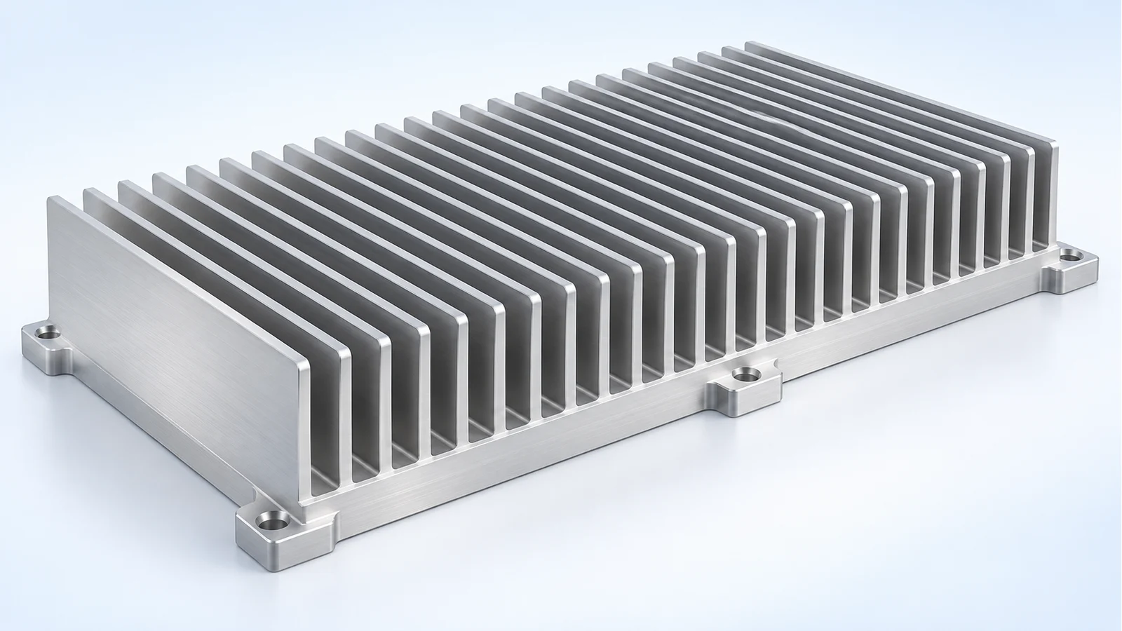
At a glance: match the heat sink to the cooling boundary
| Project condition | BAOSONG recommendation | Decision to settle |
|---|---|---|
| Natural convection, open installation space | Start with an extruded section and an unobstructed installed channel orientation. | Local air temperature, clearances and contact. |
| Fan-cooled compact enclosure | Match fin geometry to available airflow and pressure. | Actual operating flow through the fins, not free-air fan flow. |
| Concentrated device hot spot | Review base spreading and contact before adding fins. | Heat-source footprint, base and interface. |
| Only inverter output power is known | Establish the component loss map and thermal limits first. | Which heat reaches this sink and at what operating condition. |
| Approved design or transfer order | Review the accepted part and assembly baseline directly. | Material, contact, finish, installation and inspection state. |
Define the solar inverter heat-sink component
An aluminum inverter heat sink carries heat from the specified devices through its contact surface and base into a finned surface exposed to cooling air. BAOSONG’s supplied scope can be the finned body, a finish-machined base or an agreed thermal assembly. The quotation identifies its mounts, contact features and included items.
A complete inverter housing, battery cabinet and liquid-cooling system are different purchases. This article focuses on the air-cooled thermal component within aluminum renewable-energy hardware. Device selection and the inverter’s electrical control remain with the responsible product team.
Calculate the heat-sink budget from losses, not inverter output
Start with the heat dissipated into this sink over the relevant operating condition. The device loss map should identify heat-source locations and the case or junction limits used by the electrical team. Reserve the temperature drop needed inside the device and across the interface before assigning a sink-to-air target.
Thermal resistance is temperature rise divided by heat flow. Boyd’s How to Select a Heat Sink explains the junction, case, interface and sink-to-air resistance chain. A quoted resistance must be matched to its cooling conditions; it is not a fixed rating for every installation.
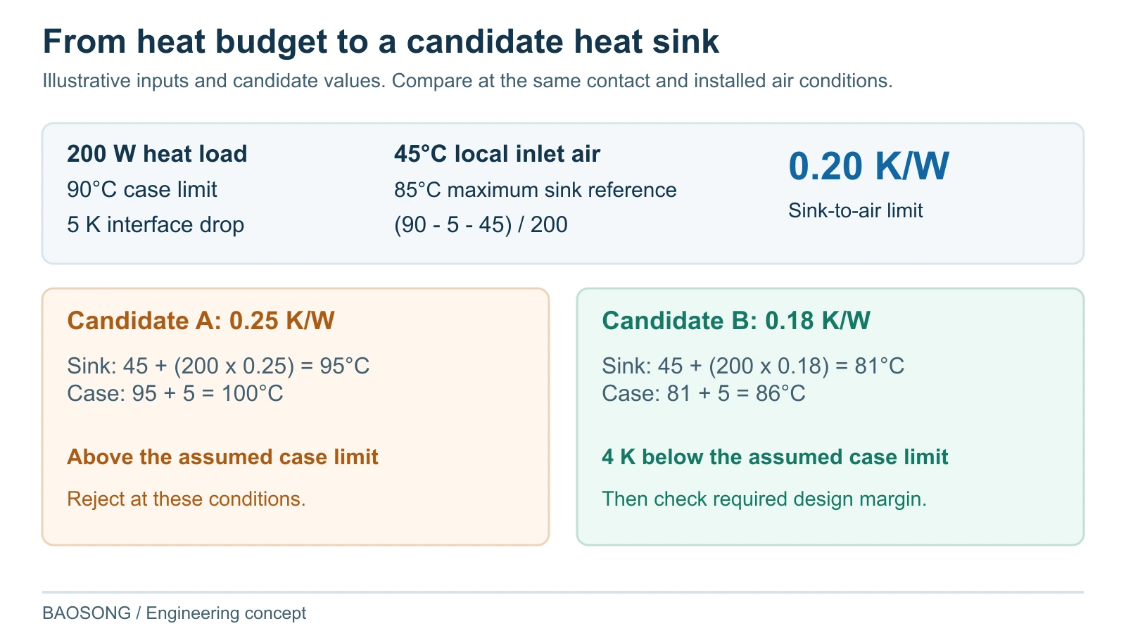
Illustrative single-source budget: assume 200 W of heat passes through one sink, a 90°C case-temperature limit, 45°C local inlet air and a 5 K case-to-sink interface allowance. The sink may reach 85°C at the contact reference, leaving 40 K to the inlet air: 40 K ÷ 200 W = 0.20 K/W maximum sink-to-air resistance in this simplified steady-state budget. These are assumed design inputs, not an inverter standard or BAOSONG performance rating.
Use that result to screen candidates under the same conditions. A sink measured at 0.25 K/W would give a 50 K sink-to-air rise at 200 W, putting the sink at 95°C and the case at 100°C with the assumed interface drop. It misses this example’s limit. A 0.18 K/W candidate gives an 81°C sink and an 86°C case under those same assumptions. That leaves 4 K below the case limit, before the product team assigns margin for variation and service conditions.
The comparison is useful only with the same heat-source footprint, contact reference, orientation and installed air conditions. These hypothetical candidate values are not measured BAOSONG performance. Additional heat sources, solar loading, recirculation and transients need their own allowance or model; the example does not calculate junction temperature.
Why start with an aluminum construction?
Aluminum can combine a spreading base, repeated fins and mounting features in a practical component. An extrusion provides a repeated section with little need to machine each fin, while selected CNC work prepares the device contact and installation interfaces. That combination is useful for solar inverter programs with a stable section and recurring demand.
The alloy and condition follow the product form, finish and mechanical requirements. If a small device footprint creates a spreading bottleneck, evaluate the base and heat-spreading arrangement before replacing the whole sink with a denser fin block. Copper inserts or heat pipes may solve a specific local problem, but their interfaces, attachment and operating conditions must justify the added assembly.
Choose the fin construction for a defined reason
We recommend extrusion plus local CNC features as the first manufacturing route when the available section, fin geometry and installed cooling can meet the budget. Move to skived or assembled fins when the geometry needs a different surface arrangement; consider heat-pipe assistance when heat must be spread from a localized source. A liquid route is an architectural alternative when air-side constraints cannot be resolved, not the default answer to a larger inverter output rating.
| Construction and fit | Benefit and tradeoff | Change trigger / verification |
|---|---|---|
| Extruded section plus CNC | Repeated base and fins with coordinated mounting/contact features. Section and fin geometry have manufacturing limits. | Change if the available section cannot meet the layout and airflow budget. Verify installed thermal performance and finished contact. |
| Skived fins | A different fin density and geometry where the base and manufacturing route suit it. Thin fins need handling protection and usable airflow. | Select for a demonstrated geometry benefit, not fin count alone. Check pressure/flow, fin integrity and production consistency. |
| Bonded or assembled fins | Useful when base size or fin layout exceeds a practical integral section. Added joints and assembly variation require control. | Use where the larger arrangement offsets its complexity. Verify joint quality, contact and installed thermal response. |
| Heat-spreading assistance | Heat pipes or a defined insert can move a localized load into more useful fin area. Adds interfaces and operating constraints. | Choose after identifying a spreading bottleneck. Verify the specified orientation, attachment and operating conditions. |
Our aluminum extrusion services review connects the section to cutting, straightness and secondary features. Precision aluminum CNC machining prepares the contact plane, holes and mounting references. Machining remains a valid recurring-production route where geometry or order economics support it.
Make the device contact and base work together
Review the device footprint, mounting instructions, contact zone and specified thermal interface material with the base geometry. A flat-looking plate can still leave an unsuitable gap or deflect under assembly. Define the condition in which the contact surface is measured, including relevant support and final finish.
One device is hot while much of the fin field stays cooler: check the device-to-base contact first, then how far the heat must spread from its footprint. We can propose a corrected contact pad, a locally thicker spreading region or a different device-to-fin arrangement. Consider a copper insert or heat-pipe assembly when a remaining spreading bottleneck warrants the extra joint and assembly work.
Much of the base is hot and contact is sound: check how air reaches and leaves the fins. Close avoidable bypass paths, keep the outlet away from the inlet and compare the fin resistance with the fan’s installed operating point. Moving to denser fins before resolving those restrictions can leave the same overheating problem. These temperature patterns guide diagnosis; they do not replace measurements of the actual assembly.
Reserve a real path for the cooling air
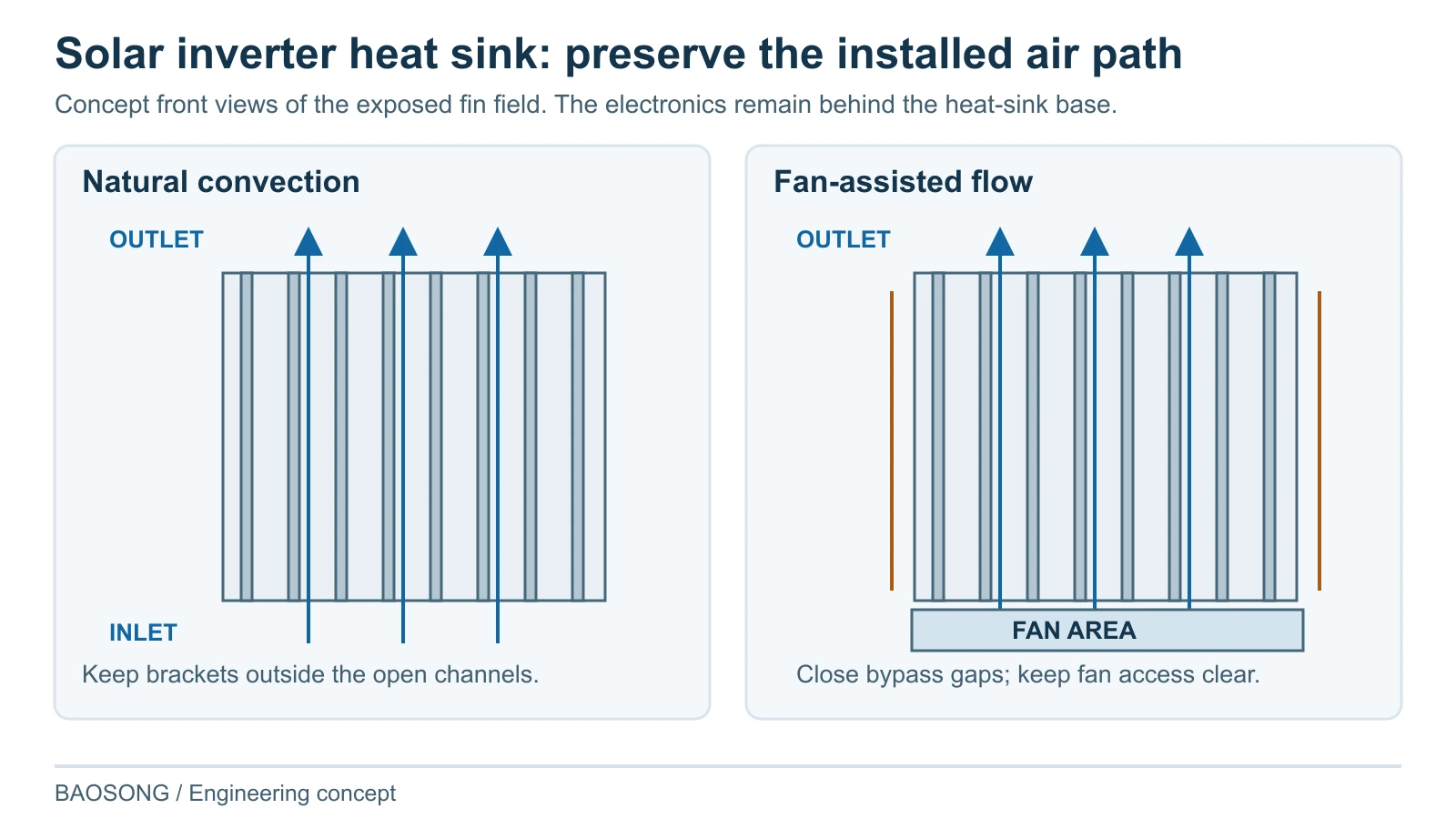
For natural convection, arrange the installed channels and surrounding clearance so buoyant air can pass through the fin field. The mounting orientation, wall distance and nearby equipment matter. For forced convection, specify the airflow through the sink at the actual system resistance; a fan’s free-air figure is not the installed operating point.
More fins can add area while also restricting flow. We compare fin spacing and length with the available pressure and installation envelope instead of treating the highest fin count as the best design. Bypass gaps and hot-air recirculation should be addressed with the equipment layout and any agreed ducting.
Make the rear heat sink accessible for cleaning and assembly
For a naturally cooled rear heat sink, we recommend channels that remain open at their lower and upper ends in the installed orientation. Keep wall brackets and cable routes out of those openings. Leave access for the intended cleaning tool without requiring the electronics cover to be opened. A tighter fin pitch is a poor trade if the site’s debris cannot be removed from it.
A heat sink used as the rear wall of a sealed inverter also needs a continuous perimeter seal land and fasteners clear of the device pads. We keep the fins and their cleaning access outside that seal. This defines the heat-sink attachment without treating the bare part as a qualified complete enclosure.
Specify the exterior corrosion protection separately from the device contact pads, gasket land and any bonding point. Mark each area’s approved coating, masking or bare-metal condition on the drawing. For mixed-metal fasteners, include the required surface and joint details rather than choosing the exterior finish by appearance alone.
Use local inlet temperature for the installed location and account for solar exposure where relevant. If cooling depends on a fan or filter, provide access to remove that service item and define the allowed operation when airflow degrades. We accommodate those access requirements in the mounting and fin layout before production.
How BAOSONG resolves the thermal component problems
| Customer problem | BAOSONG action | Customer result |
|---|---|---|
| Catalog sink fails in the installed inverter | Compare the source of the thermal rating with actual inlet air, orientation, flow and contact. | A component proposal tied to the real cooling boundary. |
| Device hot spot remains after adding fins | Review interface and base spreading against the device loss map. | A targeted base/contact or spreading change. |
| Fan upgrade produces little improvement | Review system resistance, bypass and recirculation with the fin layout. | An airflow decision based on the operating point. |
| Contact changes after finishing or assembly | Control functional surface zones, support and measurement state. | A finished interface that can be inspected consistently. |
| Thin fins arrive bent or repeat parts vary | Define handling protection and revision-linked production checks. | Geometry protected through finishing, packing and repeat supply. |
Compare heat sinks under the same conditions
BAOSONG defines the aluminum component inspection requirements with the supplied body or assembly. Thermal verification needs its own boundary and responsible party. A dimensional result, a simulation and an installed temperature test are different records.
| Question | Condition to agree | Record or handoff |
|---|---|---|
| Is the thermal budget appropriate? | Loss map, device limit, interface allocation and local inlet. | Approved budget and identified assumptions. |
| Does the device contact meet the design? | Mounting instructions, contact surface, support and finish state. | Finished contact and dimensional records. |
| Can air pass through the installed fins? | Orientation, clearance, duct/bypass and fan/system condition. | Installed flow/pressure and temperature verification. |
| Can thermal results be compared? | Same heat input, contact, air conditions and sensor reference. | Test or analysis report with those boundaries. |
| Does outdoor or service exposure change the result? | Specified exposure, fouling, cleaning and degraded operation. | Project-defined environmental/service verification. |
| Will repeat components remain equivalent? | Material, fin route, machining, finish, assembly and drawing revisions. | Representative first article and change approval. |
Two useful starting points for an OEM project
Natural-convection rear panel: for a repeated device layout with space behind the inverter, start with an extruded base and fins. Machine the device pads and perimeter seal land locally. Put brackets beside the air channels and keep the lower opening clear so the wall installation preserves the intended upward air path.
Compact fan-cooled component: if the base width is fixed, compare candidates at the airflow the fan can deliver through the installed fins and duct. Correct a local contact or spreading problem first. Use skived or assembled fins when the available section cannot provide the required geometry and the revised air-side resistance remains acceptable.
Keep recurring parts tied to the thermal baseline
For high-volume solar inverter heat sink supply, consider the section/tooling, contact machining, handling and inspection while quoting the order. The representative first article uses the intended production route and finish. A polished development sample does not establish the condition of a differently manufactured production base.
Review changes to the base, fins, mounting pattern, surface treatment, interface specification and any heat-spreading attachment against the approved assembly. Some changes affect thermal behavior even if the part still fits. We identify the affected checks and preserve the accepted configuration for repeat orders.
Why choose BAOSONG for a solar inverter heat sink?
| Your priority | BAOSONG action | What you receive |
|---|---|---|
| A thermal component with a useful target | Connect device losses, contact and installed cooling. | An explicit selection boundary and construction recommendation. |
| An economical aluminum construction | Use an extruded section where it fits; propose another fin route only for an identified geometry or thermal constraint. | A manufacturing proposal with the reason for its tooling and assembly work. |
| Contact pads ready for assembly | Machine the device pads, specify their finish and protect them during handling and packing. | Finished-part measurements tied to the contact and mounting drawing. |
| Accessible outdoor cooling | Place mounts clear of the air channels and preserve access for cleaning or fan replacement. | A heat-sink layout suited to installation and maintenance. |
We bring the heat-sink geometry into a manufacturing proposal that the thermal, mechanical and purchasing teams can use together. An approved drawing can proceed directly to quotation; a layout or cooling problem is enough to begin the discussion.
Request a solar inverter heat sink quote
Send your heat-sink drawing, device layout or sample photo for a quotation. BAOSONG will recommend the manufacturing route and provide a formal price for the specified material, finished features, assembly and quantity.
Frequently asked questions
What should I compare when sourcing a solar inverter heat sink from China?
Use the same geometry, material, contact condition, finish and quantity, and identify any assembled items. Compare thermal evidence only at matched heat input and installed air conditions. A generic profile price or free-air rating does not describe the finished inverter component.
Can inverter output power determine heat-sink size?
Not on its own. Obtain the losses that reach the sink and their locations over the operating range. Two inverters with the same electrical output can impose different thermal requirements; the available contact and cooling conditions also change the construction.
Are thinner or denser fins always better?
No. Use a fin arrangement that exposes useful area to the air the system can deliver. More area with insufficient flow can miss the target, and delicate fins add handling requirements. BAOSONG recommends the route after reviewing the actual geometry and cooling boundary.
Can CNC-machined heat sinks be supplied repeatedly?
Yes. CNC machining can support recurring production when the geometry, quantity and functional requirements justify it. Extrusion or another fin route may reduce repeated work for a suitable stable section, but a change of process still needs its own manufacturing and thermal review.
Send your drawing, device layout or thermal problem
| What you have | BAOSONG next action | What you receive |
|---|---|---|
| Approved heat-sink drawing | Review manufacturing, finish and acceptance directly. | A drawing-based quotation and proposed deviations. |
| Existing part or overheating issue | Separate contact/spreading restrictions from the installed airflow problem. | Proposed changes to the contact pads, base, fin arrangement or air path. |
| New device layout | Use the loss map and available air conditions to propose the base and fins. | A recommended construction and the conditions for checking its thermal result. |
| Transfer or repeat-production request | Compare the accepted component and process baseline. | A supply proposal with first-article and change requirements. |
Discuss your custom aluminum solar inverter heat sink with BAOSONG. Send a drawing, device layout, sample photo or short project description.