
Quick answer: how should you specify an aluminum EV battery tray?
BAOSONG develops and manufactures custom aluminum EV battery trays around the interfaces that must fit the battery pack. For a long tray with repeated side sections, our recommended starting construction is an extrusion-based frame with a suitable bottom panel and locally machined functional features. For a shallow tray with changing geometry, we recommend formed-sheet construction with selected reinforcement. We develop that route against the approved loads, geometry and production demand.
The sealing flange, module supports and vehicle mounts need a coordinated manufacturing plan. Joining can move the flange or support surfaces; machining and inspection must therefore refer to the specified joint, finish and support condition. Aluminum gives the design team useful freedom to combine lightweight sections, stiffening features and accurately machined interfaces without making the entire tray from a solid block.
Send BAOSONG a drawing, pack layout, sample photo or description of the tray problem. We will define the mechanical supply scope, recommend a manufacturing route and identify the functional features to release for quotation and production. An approved drawing can proceed directly to manufacturing review; an early concept can begin with the envelope and mounting arrangement.
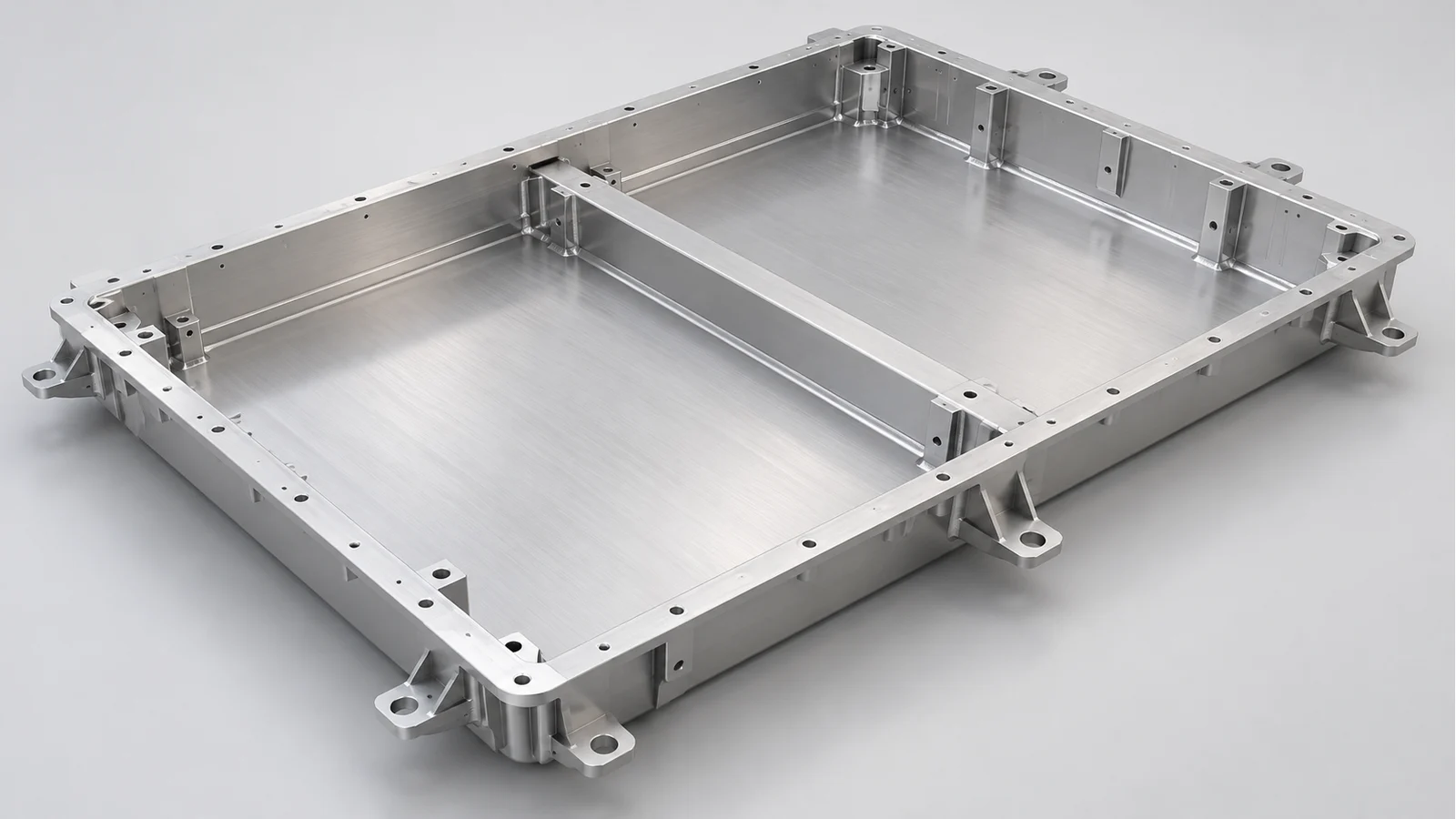
Aluminum EV battery trays at a glance
| Your project condition | BAOSONG recommendation | Decision to release |
|---|---|---|
| Long sides and repeated sections | Extrusion-based rails or crossmembers with a selected bottom construction | Section design, joint access and post-joining feature control |
| Shallow tray with changing envelope | Formed-sheet construction with reinforcement where required | Bend/joint layout and the remaining machining allowance |
| Compact tray with complex locating features | Assess a machined body or machined structural components | Tool access, material removal and recurring part cost |
| Flange passes in a fixture but causes assembly problems | Compare the specified support and restraint conditions | Whether free-state or restrained acceptance represents the requirement |
| Stable design entering repeat supply | Release the production construction and inspection baseline together | Which changes require renewed dimensional or functional evidence |
What does the tray supply include?
An EV battery tray is the lower structural carrier and its agreed mounting or closure interfaces. Depending on the design, the supplied scope can be a machined tray body, rails and crossmembers, a matched component set, or a joined mechanical subassembly. We identify that boundary before comparing manufacturing routes so the quotation describes what reaches your assembly line.
The Aluminum Extruders Council’s battery-box overview distinguishes top and bottom covers, internal structure and side-impact structure. That distinction helps prevent a tray drawing from silently absorbing every enclosure responsibility. Our battery pack enclosure guide covers the wider frame-and-cover architecture; this article concentrates on the tray’s manufacturing and acceptance.
An electric vehicle battery tray may also support a separate battery cooling plate. We coordinate its contact surfaces, fastening access and clearance with the tray. The pressure-containing plate and its coolant tests remain identifiable items, so tray dimensional approval cannot be mistaken for approval of the cooling circuit or the complete battery system.
Why choose aluminum for a custom battery tray?
Aluminum supports a low-mass structure through tailored sections, local reinforcement and selective machining. An extrusion can place material along a repeated load-carrying section; a formed panel can close a broad area; machined pads can establish the interfaces that need local accuracy. The useful result is a construction that allocates material and processing to the required function.
We select the alloy, product form and delivered condition alongside the joining route. A sheet, extrusion and casting with similar nominal chemistry do not automatically have interchangeable design properties. Welded regions, coating, drainage and contact with dissimilar materials also enter the review. Where underbody impact or corrosion exposure changes the design, BAOSONG brings that issue into the proposed construction and agreed verification scope.
Increasing alloy strength alone does not resolve an overly flexible panel. Section geometry, unsupported span and how the tray connects to the vehicle also matter. For a tray that deflects between mounting points, our first manufacturing review examines the section and support arrangement, then considers the material and interface changes that the design team can approve.
Which manufacturing route should you use?
For an extruded aluminum battery tray with long, repeated rails, we recommend designing the rail sections, bottom connection and accessible machining features as one manufacturing package. Extrusion provides the repeated section; precision aluminum CNC machining creates the local flange, locator, hole or connection geometry. This combination can serve recurring production as well as development work.
| Construction | Choose it when | Main tradeoff and change trigger | Manufacturing release |
|---|---|---|---|
| Extrusions plus bottom panel or joined sections | Long, repeated geometry benefits from integrated rails and support features | Joint count and accumulated variation need control. Reassess when the shape changes substantially across its width or height. | Define joint access, machining stock, support sequence and finished interface relationships. |
| Formed-sheet tray with selected reinforcements | A shallow shell or frequently changing size favors flexible fabrication | Joining and forming can affect the flange and supports. Compare a dedicated formed or extruded route when recurring demand justifies it. | Approve bend radii, weld/connection access, reinforcement positions and final measurement state. |
| Machined body or machined structural set | Compact geometry, complex local features or reduced tooling commitment justify material removal | Stock use and cycle time can dominate a large tray. Shift stable repeated sections into a suitable near-net form when advantageous. | Review tool reach, wall support, datum transfer and production inspection before committing the route. |
BENTELER’s original tray discussion describes extrusion and sheet alternatives and the importance of their joints. It supports comparing construction choices under actual requirements. BAOSONG’s recommendation for your tray also considers the delivered component scope, accessible features and order profile; a complete vehicle system supplier’s responsibility is a different purchasing scope.
When a formed or joined route is selected, our aluminum fabrication support connects panel preparation, joining and final interfaces. For a stable, complex local feature, we can also compare a cast node with a machined or fabricated alternative. The recommendation identifies the tooling commitment, joint interfaces and verification needed for the delivered tray.
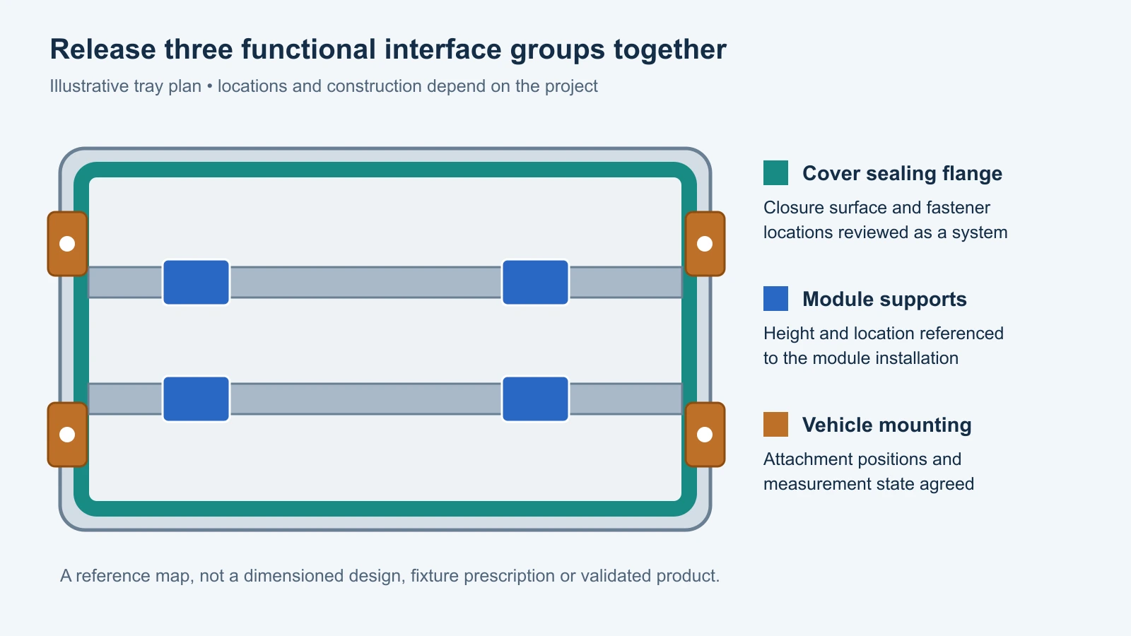
Release the three functional interface groups together
The tray’s module supports establish where internal hardware sits, the vehicle mounts connect it to the approved installation, and the perimeter flange mates with the closure. These features need a common reference relationship, even when they are made in different operations. BAOSONG prepares a feature-release sheet connecting each function to its drawing reference, manufacturing state and inspection record.
A datum is the reference used to relate the drawing’s features. We agree which physical features establish that reference during processing and inspection, then review how it transfers when the tray is joined or reclamped. The drawing’s geometric requirements should follow the specified system; ASME Y14.5 provides a framework for communicating and interpreting that intent when the project uses it.
Flange flatness is one part of closure control. The matching cover, seal design, bolt arrangement and finished surface condition also affect the assembled joint. We therefore review local sealing lands and attachment positions along with the broader flange geometry. A locally accurate strip does not, by itself, establish that the full perimeter will seal under the intended assembly conditions.
Plan joining, machining and finishing around the final interface
For a joined tray whose critical flange requires final machining, we first check that the construction leaves usable stock and access after the relevant joining operations. We also decide how the part will be supported during that machining. Removing material from a tray pulled into an artificial fixture shape can leave a different result when the clamps are released.
Where practical, geometry-changing operations precede final finishing of the affected functional surfaces. The exact sequence can vary with the joint and coating system: a sealing surface may need protection during coating, while a specified coated feature must be accepted after treatment. BAOSONG sets that sequence in the manufacturing proposal so the sealing land, module pads and external finish do not compete for incompatible requirements.
We also review joint terminations and intersections near sealing edges. A connection that is easy to make in an open frame may become inaccessible after the bottom panel is installed. Routing those operations early reduces the chance of discovering, at final assembly, that a selected tool or joining head cannot reach the required location.
How BAOSONG addresses the tray problems that delay assembly
| Buyer problem | BAOSONG action | Why it helps | Customer output |
|---|---|---|---|
| Flange moves after joining | Review joint sequence, support locations and any required final machining allowance | The final feature is planned against the construction that will actually be delivered. | Proposed sequence and agreed flange acceptance state. |
| Module holes fit but mounting heights disagree | Relate support pads and hole locations to the same functional reference scheme | Separate operations are checked against a coordinated assembly relationship. | Released interface sheet and feature inspection scope. |
| A fixture result conflicts with assembly behavior | State supports, restraints and measurement condition in the inspection plan | Readings are compared under matching conditions rather than assuming all fixtures represent the same requirement. | A reproducible measurement setup and clear report basis. |
| A finishing or production change creates new issues | Evaluate its effect on sealing, fits, joints and the evidence already approved | Change decisions follow the affected function instead of treating every variation as cosmetic. | Change-impact record and agreed repeat checks. |
How should a battery tray be inspected?
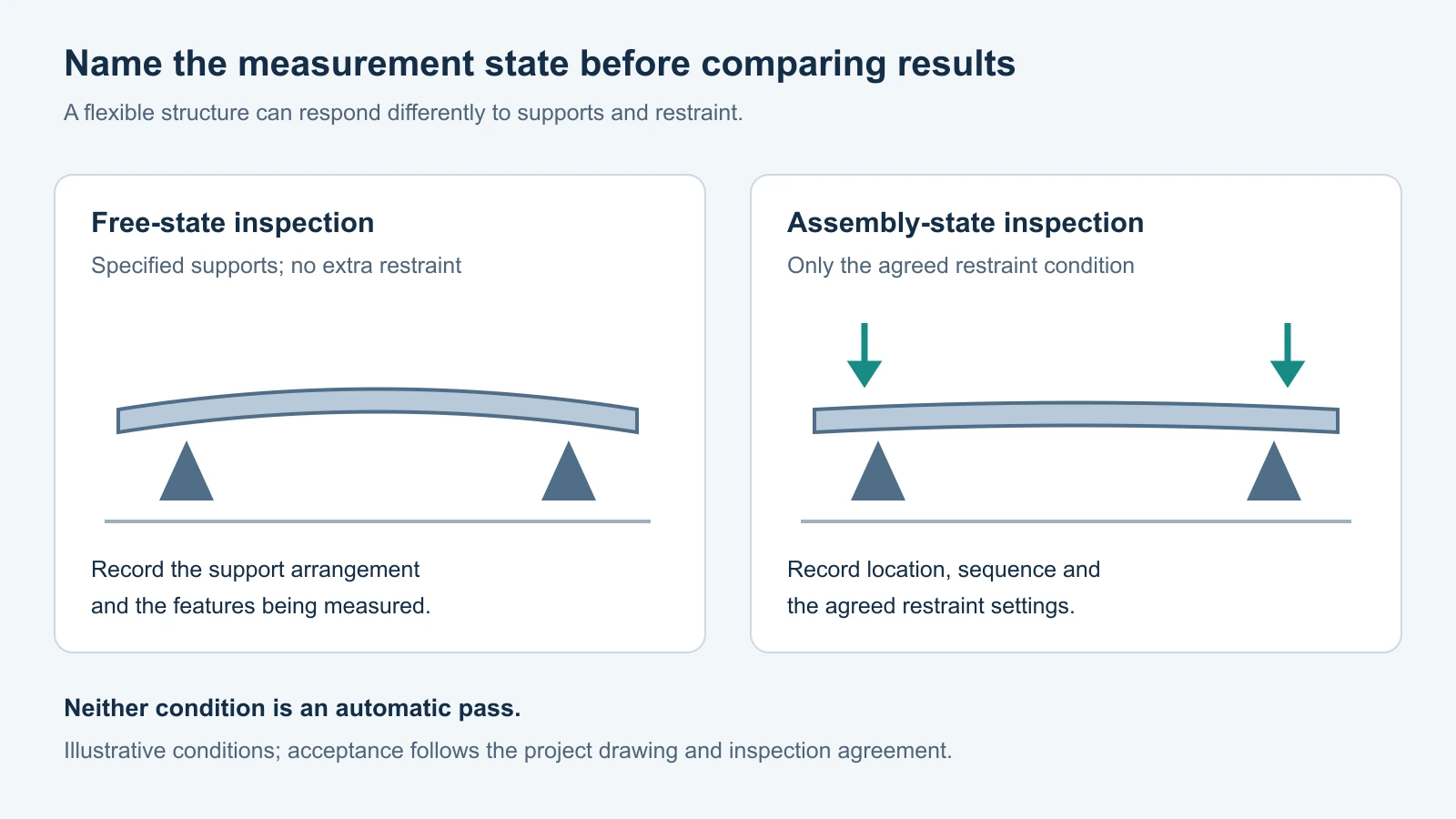
Specify whether flange flatness and related geometry are accepted in a free-state condition or under defined restraint. Free-state inspection still needs suitable support; restrained inspection needs the actual constraint arrangement stated. These are different requirements, and neither should be substituted for the other without agreement.
| Feature or function | Specify before inspection | Evidence to agree | When to revisit |
|---|---|---|---|
| Flange and closure interface | Drawing controls, reference features, support/restraint and finish condition | Dimensional report identifying the measured state and locations | Joint sequence, fixture, coating or closure design changes. |
| Module support and locating features | Support heights and positions relative to the released reference scheme | Feature results tied to the same part revision and setup | Support geometry, machining strategy or internal layout changes. |
| Vehicle attachment interfaces | Mounting locations, contact condition and installation relationship | Dimensional acceptance plus any separately assigned structural evidence | Vehicle mounts, load assumptions or joining construction changes. |
| Joints and sealed boundary | Which joints are structural, sealed or both; applicable test object and method | The specified joint inspection and, where required, dedicated sealing test record | Joint type, process window, material or sealing treatment changes. |
A dimensional report answers whether the specified features meet their requirements in the stated condition. Structural, corrosion, water-ingress and vehicle-level qualification address different questions. BAOSONG aligns the component inspection with the agreed quality and inspection plan; the project assigns any wider validation responsibilities before release.
From first supply to mass production
For mass production, release the representative construction, material condition, joining method, fixture references and acceptance plan together. A development part made with a different joint or bottom-panel arrangement can help assess fit, but it does not automatically represent the final construction’s performance. We identify which evidence transfers and which affected features need another check.
For an approved build-to-print tray, BAOSONG reviews manufacturability and quotation directly against the released drawing. For a transfer project, we compare the drawing with the sample and existing acceptance record, resolve differences, and agree the first-article basis. Development projects receive a proposed construction and the interface decisions needed to make the next design revision useful.
Repeat orders use a change-impact record: what changed, which functional surfaces or joints it affects, which previous approvals remain relevant, and what evidence must be renewed. This makes batch consistency an operational task. It also prevents an apparently minor change in material state, coating, fixture restraint or machining sequence from bypassing the agreed acceptance baseline.
Two ways to apply the tray decision
Illustrative long-pack project: the tray envelope is stable and the side geometry repeats along its length. We recommend screening extruded rails with a selected bottom construction, preserving joint access and leaving local stock where the closure interface needs machining. The release decision ties the finished flange and module supports to the vehicle mounting references.
Illustrative shallow tray with frequent layout changes: we recommend screening formed sheet with selective reinforcements and machined locating features. The proposal identifies the joints that can move the flange and the measurement state that represents the intended fit. If the layout stabilizes and recurring demand changes the economics, we compare dedicated forming or extrusion features using the approved geometry and inspection scope.
Why bring your EV battery tray project to BAOSONG?
BAOSONG connects the component’s geometry with a manufacturing and acceptance plan. Our drawing and manufacturing review focuses on the features that determine assembly success, then turns those decisions into a defined supply scope.
| Purchasing priority | BAOSONG action | What you receive |
|---|---|---|
| A quotation that matches the actual delivery | Define tray body, structural set, joining, finishing and agreed inspection boundaries | A proposal whose scope can be compared with your assembly needs. |
| Fit across several operations | Coordinate flange, supports, mounts and their reference/measurement conditions | One interface-release basis for manufacturing and acceptance. |
| A route suited to recurring demand | Compare stock form, tooling, joint access and local machining at quotation stage | A reasoned construction choice with clear change triggers. |
| Repeat supply after approval | Maintain drawing revision, critical-feature records and change-impact requirements | A usable baseline for first articles, repeat orders and engineering changes. |
Request an EV battery tray quote
BAOSONG prepares a formal EV battery tray quote after reviewing your drawing or requirements, the delivered scope, material, quantity and agreed acceptance conditions. Send your current information and we will identify the remaining decisions needed for an accurate quotation.
EV battery tray manufacturing questions
Does a custom tray always need a prototype before quotation?
No. An approved design can move directly into manufacturing review and quotation, with samples or first articles arranged to the order requirements. For an evolving design, we recommend a representative part or feature trial only where it resolves a specific uncertainty, such as joint access, interface fit or a manufacturing change.
When is an extruded aluminum battery tray a useful choice?
An extruded aluminum battery tray is useful when repeated rail or crossmember sections can carry the required functions efficiently. The design still needs a suitable bottom construction, accessible joints and locally controlled interfaces. We compare the entire delivered structure so a convenient extrusion section does not create unnecessary joining or finishing work elsewhere.
What should you align when sourcing an aluminum battery tray from China?
Use the same drawing revision, material/product form, joint scope, finish state and measurement conditions when comparing a China sourcing proposal. BAOSONG turns those requirements into a project handoff that identifies what is included, which records accompany the tray and how changes are approved. This gives your purchasing and receiving teams a shared acceptance basis.
Start with the tray information you already have
| What you have | What BAOSONG does next | What you receive |
|---|---|---|
| Approved drawing and quantity | Review route, functional features and delivery requirements | Manufacturing proposal and formal quotation scope. |
| Sample tray or photos of an assembly problem | Identify the affected interface and the information needed to characterize it | A focused review path and proposed manufacturing changes. |
| Pack envelope or early layout | Compare construction routes and establish mounts, supports and closure priorities | An interface and construction direction for the next design step. |
| An existing source or repeat order | Review the released baseline, known issues and transfer/change evidence | An agreed first-supply and continuing-production handoff. |
Request your custom aluminum EV battery tray proposal and quote. Send a drawing, sample photo, layout or short description. BAOSONG will help turn the tray’s mounting, sealing and manufacturing requirements into an actionable supply plan for your EV aluminum component project.