
Quick answer: how should an aluminum liquid cooling plate be designed for an EV battery?
Design an aluminum liquid cooling plate from the battery heat-load map, allowable cell or module temperatures, temperature-uniformity target, coolant properties, flow range and pump capability. Then balance channel geometry, pressure drop, thermal-interface resistance, plate stiffness, joint integrity, corrosion, cleanliness and manufacturability. Optimizing only peak temperature can create excessive pump demand or a weak pressure boundary.
Select the manufacturing route with the channel architecture. CNC-machined and sealed plates support rapid prototypes and complex local paths; extruded multi-port profiles suit constant channels; formed or stamped plates can create shallow large-area circuits; brazed and roll-bonded assemblies require process-specific alloy systems and joint validation. No single aluminum alloy or construction is best for every pack.
Verify the complete cold plate under defined operating and test conditions. Measure heat-transfer performance, temperature distribution, pressure drop, flow balance, leakage, pressure strength, thermal cycling, coolant compatibility, cleanliness and port loads. Keep the internal coolant circuit separate from the battery enclosure’s external ingress boundary.
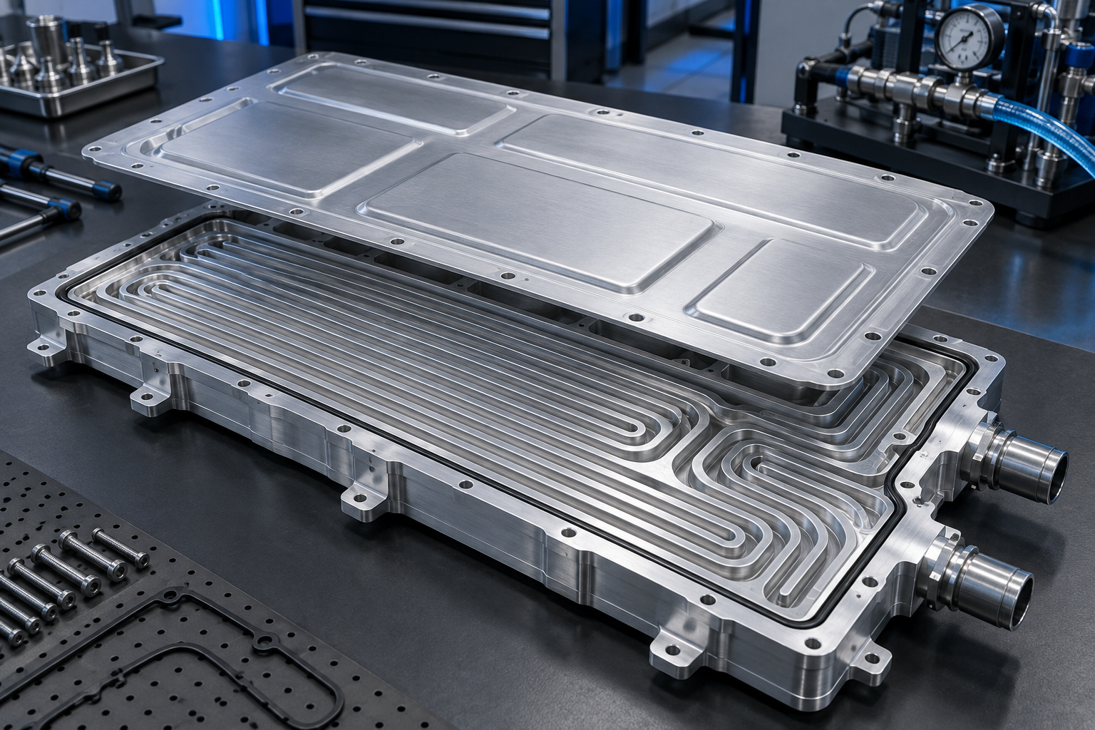
Define the cold plate as part of a thermal system
Start with this decision sequence before drawing channels:
- Freeze the operating inputs. Define the heat map, coolant, flow and temperature range, pump curve, duty cycle and allowable battery temperatures.
- Set measurable outputs. State maximum temperature, temperature spread, pressure-drop limit, allowable leakage and structural limits at named test conditions.
- Select the architecture and process together. Compare serpentine or parallel flow, ports, manifolds and thermal contact with machined, extruded, formed, brazed or roll-bonded construction.
- Detail the pressure boundary. Control minimum wall, joints, ports, flatness, cleanliness, corrosion and every feature that can leak or restrict flow.
- Correlate analysis with hardware. Test thermal performance, hydraulics, leakage, proof strength and durability on production-representative parts.
A cooling plate does not control battery temperature by itself. Heat moves from cells or modules through contact surfaces, thermal-interface material, the aluminum wall and channel convection into coolant, then through the vehicle’s pump, valves, chiller, radiator and controls. Each resistance and control state can limit system performance.
Begin with the operating envelope: charge and discharge heat generation, ambient conditions, initial temperatures, coolant inlet conditions, flow availability, transient duty cycles, allowable cell-to-cell variation, warm-up needs and fault cases. State whether the plate cools cells directly through a module base, supports pouch-cell fins or serves another architecture.
The U.S. Department of Energy’s extreme-fast-charging technology gap assessment describes liquid cooling as a widely used battery thermal-management strategy while also noting additional connections and potential failure paths. Treat the plate as a pressure component inside an electrical and safety system.
Write measurable input requirements
| Input | What to specify | Design effect | Verification |
|---|---|---|---|
| Heat load | Spatial and time-dependent heat map for defined operating cases | Channel placement, flow split and thermal mass | Model correlation and instrumented thermal test |
| Temperature | Maximum, minimum and uniformity targets at defined locations | Thermal resistance and flow requirements | Sensor map and steady/transient test |
| Coolant | Composition, concentration, property range, contaminants and service interval | Convection, pressure drop, corrosion, seal and cleaning choices | Fluid control and compatibility testing |
| Hydraulics | Available flow, inlet pressure, pump curve and allowable plate pressure drop | Channel size, length, parallel paths and manifolds | Flow-versus-pressure characterization |
| Pressure boundary | Operating, proof, burst and transient conditions with temperature and cycles | Wall, cover, joint, ports and local reinforcement | Defined leak, proof, burst and fatigue tests |
| Interfaces | Contact area, flatness, TIM, clamp load, mounts, ports and hose loads | Contact resistance, deformation and local stress | Final-assembly dimensional and functional tests |
| Production | Quantity, tooling, traceability, inspection and change control | Machined, extruded, formed, brazed or hybrid route | Representative first article and process capability evidence |
Do not copy temperature, flow or pressure values from another battery platform. Cell chemistry, pack arrangement, duty cycle, coolant loop and control strategy change the correct targets. Record who owns each input and how later revisions are approved.
Balance heat transfer, temperature uniformity and pressure drop
More channel area or higher velocity can improve local convection, but narrow or long paths can raise pressure drop. Multiple parallel paths reduce path length but can distribute flow unevenly when manifolds or branch resistances differ. Sharp turns, port transitions and sudden area changes can create local losses or stagnant regions.
SAE technical work on battery liquid-cooling pressure drop and heat transfer demonstrates why the two outputs must be assessed together. A later SAE study on cooling-plate geometric parameters likewise evaluates temperature distribution, pressure drop and power consumption as connected design objectives.
Use the real pump curve and system resistance rather than assuming a fixed flow through every design. A plate with lower calculated resistance may receive more flow in one circuit and starve another parallel branch. Test the cold plate both alone and in the representative loop.
Choose a channel architecture that can be manufactured
Serpentine channels provide one continuous route and predictable sequence, but total length can increase pressure loss and coolant temperature rise. Parallel circuits reduce length and can improve coverage, yet need manifolds that distribute flow reliably. Hybrid paths can target high heat zones while controlling system resistance.
Set channel width, depth, spacing, turns, roof thickness and ligament dimensions from thermal-hydraulic analysis plus pressure, fatigue and manufacturing limits. Avoid decorative complexity that adds joints, burr traps or inspection difficulty without measurable thermal value.
Include drainability and air removal. High points can trap gas, low points can retain coolant during service, and blind regions can hold cleaning fluid or debris. Orient ports and internal paths for filling, venting, flushing and final drying as required by the assembly process.
Compare aluminum cold-plate manufacturing routes
| Route | Suitable geometry | Production value | Main controls |
|---|---|---|---|
| CNC-machined base plus cover | Complex local channels, manifolds, ports and fast design changes | Low-tooling prototypes and controlled local features | Cycle time, burrs, sealing/joining, distortion, cleanliness and material use |
| Extruded multi-port profile | Long constant channels and repeated cross-sections | Integrated passages with less channel machining | Die feasibility, channel consistency, cut ends, end closure and port joining |
| Formed or stamped sheets | Shallow large-area channels and embossed flow paths | Material-efficient production after tooling | Springback, thinning, flange control, joining and channel collapse |
| Brazed plate assembly | Thin passages, manifolds and heat-exchanger-style construction | Large bonded area and scalable thermal hardware | Clad/core system, braze cycle, erosion, distortion, corrosion and joint quality |
| Roll-bonded panel | Inflated internal paths in thin sheet constructions | Low-profile, large-area coverage | Bond pattern, inflation consistency, channel strength, ports and fatigue |
| Hybrid construction | Extruded channels with machined manifolds or formed plates with local blocks | Places each process where it adds value | More interfaces, seals, joints, tolerance stacks and traceability |
The route should follow stable geometry and expected volume. Prototype machining can verify packaging and thermal concepts quickly, but a production stamped or brazed plate will have different wall behavior, joint properties and tolerances. Plan a representative-process validation before design release.
Design CNC-machined cold plates for sealing and cleaning
A machined two-piece plate can create variable-depth channels, local turbulence features, manifolds and integrated ports. Keep tools accessible, give internal corners practical radii and avoid very thin walls that distort during machining or pressure. Long shallow plates need a fixturing and stress-relief strategy.
Define the cover attachment: gasket, adhesive, welding, brazing, friction stir welding or another qualified process. The joint changes groove geometry, land width, flatness, heat input and inspection. A removable bolted cover may support prototypes but may not represent the production joint.
Deburr internal edges without leaving loose particles or changing controlled restrictions. Establish a wash, flush, dry and inspection procedure. Precision aluminum CNC machining can create prototypes and functional interfaces, but the project drawing must define the final pressure boundary and cleanliness state.
Design extruded cooling profiles around end closures
Multi-port extrusion can produce continuous channels with thin separating webs and integrated mounting features. The cross-section must support metal flow, die strength, quenching, straightening and inspection. Channel geometry that appears easy in CAD may be difficult to extrude or clean.
The cut ends become a central engineering problem. Plugs, caps, manifolds, welds or brazed closures must contain pressure and distribute flow without blocking passages. Place end machining and port connections where tools, joining equipment and inspection can reach them.
Confirm channel-wall consistency and internal surface condition through a suitable control plan. Sample destructive sectioning, nondestructive methods and flow data may serve different purposes. Review aluminum extrusion services while the cross-section is still adjustable.
Formed, brazed and roll-bonded plates need process-specific material systems
Stamped or hydroformed channels can cover a large area with thin sheet, but forming changes wall thickness and flange geometry. The mating sheet and joint process determine whether the circuit remains sealed under pressure and thermal cycling.
Brazing depends on a qualified core, clad and filler system plus surface condition, atmosphere, fixturing and thermal cycle. A material that machines well is not automatically suitable for brazing. The cycle can change strength, dimensions and corrosion behavior.
Roll bonding joins sheet before channels are inflated. Bond pattern, inflation control, local thinning and port attachment define performance. Treat supplier process knowledge as part of design feasibility, and validate representative panels rather than assuming data from a different channel pattern.
Aluminum sheet fabrication can support formed covers and plate components where the forming and joining sequence matches the pressure design.
Select aluminum for the construction and coolant
Alloy selection follows product form and manufacturing route. Machined designs often begin with a machinable wrought plate alloy; extruded channels use a suitable extrusion alloy; brazed systems use compatible core and clad materials; formed and roll-bonded plates use process-qualified sheet.
Compare thermal conductivity, strength in the final process state, formability, extrusion behavior, machinability, braze or weld compatibility, corrosion resistance and availability. Do not compare datasheet properties without aligning temper, thickness, test direction and post-process condition. Coordinate any protective treatment with the complete aluminum surface-finishing system.
Coolant chemistry, inhibitor package, concentration, contaminants and temperature affect aluminum and every dissimilar metal in the loop. Validate the complete material system: plate, joints, ports, seals, fasteners, coolant and any residual process chemistry.
Control the thermal interface and plate flatness
Heat must cross the cell or module interface before reaching the coolant. Thermal-interface material thickness, conductivity, wet-out, compression and aging can dominate the path. A high-conductivity aluminum plate cannot compensate for large air gaps or inconsistent contact pressure.
Define the contact-area datum, flatness in the relevant assembly state, allowable step at joints, TIM specification and clamp-load range. Thin plates can bend under coolant pressure, fastener preload or module weight. Check deformation across operating pressure and temperature, not only on an unloaded inspection table.
NIST research on thermal transport in multilayer materials and interfaces reinforces the need to account for interface resistance rather than relying on bulk material conductivity alone. Project validation should measure the assembled thermal path.
Design ports and manifolds for real hose loads
Ports introduce local stress, sealing interfaces, dead volume and flow disturbance. Define tube, fitting or connector standard, installation torque or retention method, supported hose mass, assembly misalignment and service loads. Keep loads from entering thin channel roofs or fragile joints.
Shape manifolds to distribute flow across parallel branches and avoid trapped air. Add inspection access or measurable features where practical. If a separate manifold is machined or cast, control the interface datum, joint and galvanic couple.
Protect ports during cleaning, storage and transport. Caps must be compatible with the specified cleanliness state and should not shed particles or leave residue.
Choose the joining method before finalizing the plate
Gaskets support serviceable closures but require compression control, fastener distribution and groove design. Adhesives can seal broad areas but depend on surface preparation, bond-line thickness and cure. Welding and friction stir welding create permanent joints with heat and distortion. Brazing joins broad surfaces through a high-temperature cycle and needs its own alloy system.
Place joints outside the highest stress or most thermally sensitive region where feasible. Design run-on/off features, weld lands, adhesive stops and inspection access. Define whether critical surfaces are finish-machined before or after joining.
For welded components, aluminum welding requirements should cover the joint process, heat-affected condition, distortion, inspection and repair rules. Parent-metal properties do not automatically represent the finished joint.
Separate leak, proof and burst requirements
A leak test finds a flow path through the pressure boundary at a defined sensitivity and condition. A proof test demonstrates survival without unacceptable deformation or leakage under a specified load. A burst test characterizes failure at a higher load. These tests answer different questions and need separate acceptance criteria.
SAE J3277_202404 presents a methodology for production-line liquid leak-tightness evaluation of EV battery packs, including coolant circuits, and states that it is an informational precursor to later work. It does not supply one universal leakage value for every cold plate.
ASTM’s current leak-testing standards catalogue includes guidance for method selection plus hydrostatic, pressure-decay, bubble and mass-spectrometer practices. Select a method from required sensitivity, test medium, volume, cycle time, contamination risk, temperature and correlation to the actual coolant leak requirement.
State test pressure, medium, temperature, stabilization, duration, allowable leakage, port closure, fixturing and whether the part is tested before or after coating and thermal cycling. Gas and liquid tests can behave differently; correlation belongs in the validation plan.
Make cleanliness a drawing and process requirement
Machining chips, abrasive particles, flux, oxide, oil, cleaner and moisture can obstruct channels, damage pumps or contaminate coolant. Define permissible particles or residue using the project’s fluid-cleanliness method, then design channels, ports and process access so the requirement can be achieved and verified.
Control the sequence from deburring through washing, flushing, drying, leak testing and capping. A leak-test medium can recontaminate a clean part if its filtration and handling are not controlled. Blind cavities and low points need special drain and dry provisions.
Preserve cleanliness during packaging. Use protected individual parts, clean compatible caps and traceable status labels. Reinspection after transport may be required for critical deliveries.
Validate thermal performance with simulation and test
CFD and conjugate heat-transfer models can compare channel concepts, but predictions depend on cell heat generation, contact resistance, coolant properties, turbulence model, boundary conditions and mesh quality. Document assumptions and sensitivity studies.
Correlate the model with an instrumented prototype. Measure inlet and outlet temperature and pressure, flow, plate surface temperatures and cell or heater temperatures at defined locations. Compare steady and transient cases, multiple orientations where air affects filling, and tolerances that influence contact or channels.
SAE J1994_202602 outlines laboratory tests for heat-transfer and pressure-drop performance of vehicle and industrial heat exchangers under specified conditions. Confirm its applicability to the project’s cold plate and supplement it with battery-specific interface and duty-cycle validation.
Test durability in the final assembly context
Evaluate pressure cycles, thermal cycles, vibration, shock, coolant aging, corrosion and combined loads according to the vehicle program. Ports, cover joints and support transitions often experience different stresses from the center of the plate.
Test the plate with representative restraints and hose or connector loads. A rigid bench fixture can hide deformation or joint loads that occur in the battery assembly. After cycling, repeat leak, flow, pressure-drop, flatness and thermal checks as required.
The cold plate supports battery thermal management but does not certify the complete rechargeable energy storage system. Apply the current regulations, standards and OEM requirements at component, pack and vehicle levels with a written responsibility matrix.
Plan prototype and production evidence separately
A machined prototype can establish channel layout, ports and early thermal response without production tooling. It may not represent a stamped sheet’s wall thickness, a brazed joint’s thermal cycle, an extrusion’s internal tolerance or a roll-bonded path’s local shape.
Before release, validate parts made from production-representative alloy, tooling, forming, joining, cleaning and inspection. Connect first-article evidence to controlled quality and inspection records, and define change triggers for material source, die or tool, joining program, coolant-contact chemistry, cleaning process and leak-test equipment.
Use engineering support to align geometry, process access and verification inputs before committing production tooling.
A practical liquid-cooling-plate development workflow
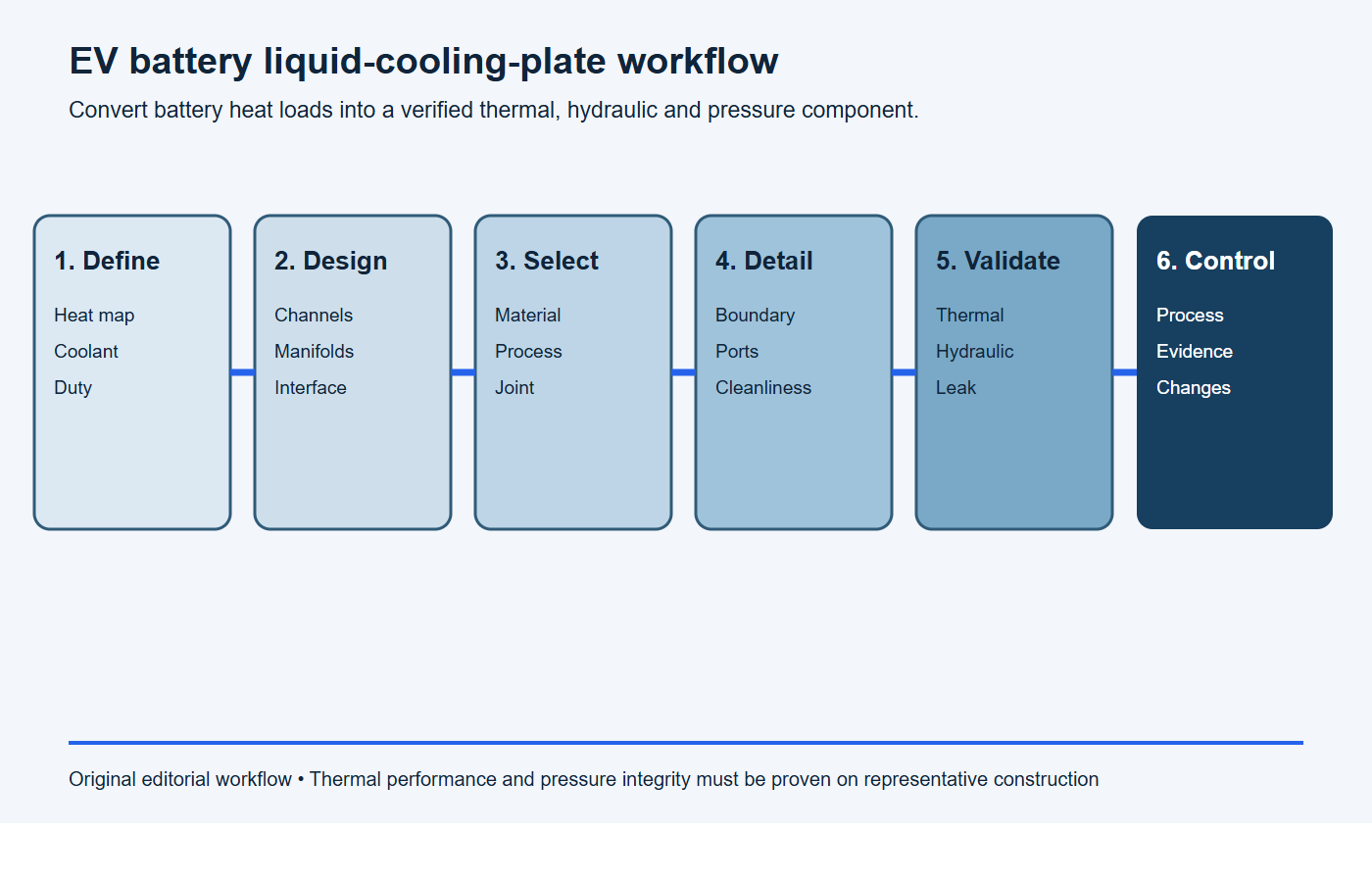
- Define the system. Record heat maps, temperature targets, coolant, flow, pump, pressure and duty cycles.
- Select the architecture. Choose contact arrangement, channel topology, manifolds, ports and assembly constraints.
- Select the process. Match machined, extruded, formed, brazed, roll-bonded or hybrid construction to geometry and volume.
- Detail the pressure boundary. Control walls, cover joint, ports, datums, TIM surface, cleanliness and inspection state.
- Correlate and validate. Link CFD to thermal, hydraulic, leak, pressure and durability tests.
- Release production controls. Preserve material, process, test, traceability and change-control evidence.
RFQ checklist for an aluminum EV battery cold plate
Use this copy-ready scope in the RFQ, then attach the controlled drawing, CAD model, heat map and validation matrix.
RFQ scope: Please quote [cold-plate part number and revision] for [prototype quantity] and [annual volume]. Design inputs are [heat-load map], [coolant and concentration], [inlet-temperature range], [flow range], [pump curve or pressure-drop limit], [operating pressure], [proof pressure], [temperature target] and [temperature-uniformity target]. Quote the proposed aluminum product form, channel architecture, manufacturing route, joining method, tooling, unit price, lead time and capacity. List every assumption and requested deviation.
Required evidence: Provide material traceability, dimensional inspection, thermal and pressure-drop results, leak-test method and sensitivity, proof or burst evidence where specified, cleanliness results, special-process records, first-article documentation and change-control triggers. Identify tests that remain the pack integrator’s responsibility.
- 2D drawing, 3D model and pressure-boundary definition;
- battery or module heat-load map and operating cycles;
- temperature targets, sensor locations and uniformity criteria;
- coolant specification, concentration, property and contamination limits;
- flow range, pump curve, allowable pressure drop and loop arrangement;
- operating, proof, burst and cycle conditions;
- material, product form, joining route and surface requirements;
- TIM, clamp load, contact flatness and assembly state;
- ports, fittings, hose loads, venting, filling and draining;
- cleanliness, flushing, drying, capping and packaging;
- leak method, sensitivity, medium, temperature and correlation;
- thermal, hydraulic, corrosion and durability validation responsibility;
- prototype and production quantities, reports and change control.
Stop conditions: the cold plate is not ready for release
Pause tooling or production release when any condition below remains open. These gaps prevent a supplier from choosing a defensible channel, wall, joint or inspection process.
- the heat map, coolant properties, flow range or pump capability is missing;
- temperature uniformity and pressure drop have no common operating point;
- the pressure boundary, leak rate, test medium, pressure, temperature or stabilization time is undefined;
- minimum wall thickness and joint acceptance cannot be inspected with the proposed process;
- the thermal-interface material, clamp load, contact flatness or assembly state is unknown;
- ports have no defined hose loads, torque, venting, filling or draining condition;
- coolant compatibility, galvanic couples, cleanliness, flushing or shipping caps are unresolved;
- a machined prototype is being used to qualify a different production alloy, joint or wall construction without a validation bridge.
Frequently asked questions
Which aluminum alloy is best for an EV battery cooling plate?
The manufacturing route determines the shortlist. Machined, extruded, brazed, formed and roll-bonded plates need different alloy and product-form properties. Compare final-state strength, thermal conductivity, corrosion, forming or joining behavior and availability.
Is a serpentine channel better than parallel channels?
Neither is universally better. Serpentine paths simplify flow sequence but can raise pressure drop and coolant temperature rise. Parallel circuits can reduce path length but require reliable flow distribution. Evaluate both within the real pump and heat-load system.
Can CFD replace cold-plate testing?
No. CFD is valuable for comparison and optimization, but its result depends on inputs and model choices. Correlate it with instrumented thermal and hydraulic tests using representative parts and interfaces.
Should a cold plate be leak-tested with air or liquid?
Select the medium and method from required sensitivity, production time, safety, contamination and correlation to the actual coolant requirement. Document pressure, temperature, stabilization and allowable leakage.
Does lower pressure drop always mean a better plate?
No. Lower pressure drop may reduce pump demand, but the changed flow path must still provide adequate heat transfer and temperature uniformity. Evaluate hydraulics and thermal performance together.
Can a machined prototype qualify a brazed production plate?
It can validate some geometry and thermal concepts, but it does not qualify production wall thickness, joints, alloy state, distortion or corrosion. Repeat applicable validation on representative production construction.
Request an aluminum liquid-cooling-plate review
BAOSONG can review cold-plate geometry, machining or extrusion routes, formed components, ports, sealing lands, joining access and inspection inputs within the supplied project scope. Send the models, heat-load requirements, coolant conditions, quantities and validation plan through contact us for a project-specific manufacturing review.
Recommended Downloads for Aluminum Alloy Selection
Use these BAOSONG references to compare alloy families, temper conditions, machinability, strength, corrosion resistance and design implications before quotation.
- Aluminum Alloy Comparison Chart (editable Excel)
- Tolerance Reference Guide (PDF)
- Aluminum CNC Machining Design Guide (PDF)
- Aluminum Part Design Checklist (editable Excel)
Need help choosing an alloy or temper for your application? Contact BAOSONG Precision.
