
Quick answer: custom aluminum PCS inverter housings
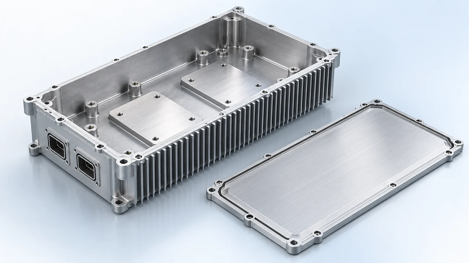
BAOSONG manufactures custom aluminum PCS inverter housings with the module mounts, cooling base and electrical connections designed to fit together. For an air-cooled unit with a repeated section, we recommend a finned extrusion with machined module pads and end closures. Use a separate cooler when it must be replaced or changed independently of the enclosure. A stable body with complex supports and connector walls is a good candidate for casting plus CNC machining.
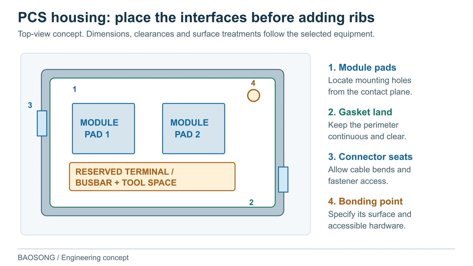
Aluminum lets the same part spread heat, support the power modules and carry the cover. We locate the module pads first, then arrange terminal access, connector openings, the gasket path and bonding points around them. This avoids discovering at assembly that a busbar bolt cannot be reached or the cover interferes with a connector.
Send your housing drawing, module layout or sample photo to BAOSONG. We will recommend the body construction, mark the features that need machining or masking, and quote the housing or mechanical assembly you need.
At a glance: start with the thermal and mounting architecture
| Project condition | BAOSONG recommendation | Interface to settle |
|---|---|---|
| Constant section and repeated lengths | Extruded finned body with local CNC features. | Module plane, cover/end plates and airflow envelope. |
| Complex integrated geometry, stable demand | Cast body with critical interfaces machined. | Tool access, machining stock, seal lands and inspection state. |
| Frequent layout changes or local precision | Machined body or modular base and cover. | Contact, mounting and connector relationships. |
| Liquid-cooled power module | Use a separate cold plate when cooler replacement matters; integrate the coolant base when packaging justifies it. | Heat path, port access and the exact coolant-containing wall or joint. |
| Established design or supplier transfer | Review the accepted housing and production baseline directly. | Drawing revision, surface zones and any proposed deviations. |
What is included in a PCS inverter housing?
A PCS is a power conversion system. The PCS inverter housing discussed here is its module-level mechanical enclosure, thermal base or agreed housing assembly. An energy storage inverter enclosure can also mean a large outdoor cabinet, so the quotation must identify the actual purchased object.
For a power conversion system enclosure at module scale, we can quote the body and cover, or a mechanical assembly with the specified cooler, seals and mounting hardware. The quotation lists what is included. This aluminum power electronics housing is built around the selected modules; it is not a supply offer for the converter electronics or control system.
This work fits our aluminum energy storage components offering. The larger BESS battery enclosure has different load, access and installation decisions. Keeping those scopes distinct makes both the quotation and the engineering handoff useful.
Use aluminum to combine heat spreading and mechanical interfaces
Aluminum allows the housing to combine a thermal base with walls, mounting features and external cooling surfaces. Extrusion repeats a useful section, casting integrates features in several directions, and machining coordinates the local surfaces that determine assembly. This makes aluminum a strong starting point when thermal contact and mechanical integration must work in the same part.
Choose the alloy with the manufacturing route. An extrusion suits repeated fins and rails; a casting can combine connector walls, ribs and bosses; a machined base gives freedom to place local contact pads. We specify the material and finish for that construction. Module contact and installed airflow still determine how much of the aluminum’s heat-spreading ability the assembly can use.
Which manufacturing construction should you choose?
For an air-cooled module with a suitable constant section, we recommend extrusion plus CNC machining of the module plane, mounting and end features. Use casting when the approved layout needs integrated bosses, pockets and interfaces that justify its tooling. Use a machined body when geometry, order pattern or design changes make it the better production route. CNC is not restricted to early prototypes.
| Construction and fit | Benefit and tradeoff | Change trigger / release check |
|---|---|---|
| Extruded body plus CNC and end closures | Repeated fins, walls or mounting channels from one section. End features and local planes still need coordinated machining. | Change if cross-section limits conflict with connectors or device layout. Check the finished contact plane and closure interfaces. |
| Cast body plus critical machining | Complex local geometry with integrated supports and features. Tooling, draft, machining stock and local casting quality require planning. | Choose when stable geometry and demand justify tooling. Inspect machined functional areas and the specified assembled boundary. |
| Machined body or base-and-cover assembly | Flexible layout and closely related thermal/mounting features. Material removal and workholding affect cost and distortion. | Retain for repeat orders when justified; compare tooling routes when demand and design stabilize. Check the finished supported condition. |
| Modular housing with a separate cooler | Useful when the electrical enclosure and heat-removal device have different construction needs. Adds interfaces and assembly work. | Use when separating functions improves the layout or service path. Verify device contact, cooler mounting and the actual seal boundary. |
Our precision aluminum CNC machining review identifies tool access, references and the sequence for those features. Where casting is selected, machining of aluminum castings brings the critical planes, holes and sealing features into their final relationship. The quotation includes the intended production route and agreed verification scope.
Choose the module-to-cooler construction
Integrated air-cooled body: machine the module contact pads on the inside of a finned aluminum base. Heat passes through the thermal interface and base to the outside fins, while the electronics cavity stays closed. We place the module pads over usable fin area and keep the mounting brackets out of the inlet and outlet path.
Housing with a separate cooler: choose this when the cooler needs independent servicing or different versions of the PCS share one enclosure. A closed base bolted to an external cooler adds a contact joint that must be included in the thermal budget. Alternatively, the cold plate can form the floor of the enclosure, with the housing sealed around it. We recommend the second arrangement when avoiding that extra thermal joint matters and the surrounding enclosure seal can be accommodated.
Integrated liquid-cooled base: use the housing floor itself to carry the coolant channels when height and part count justify the additional joining and pressure checks. A module designed for direct coolant contact is a separate architecture: its mounting and seal must follow that module’s instructions. We identify the actual coolant-containing parts before detailing the ports and cover.
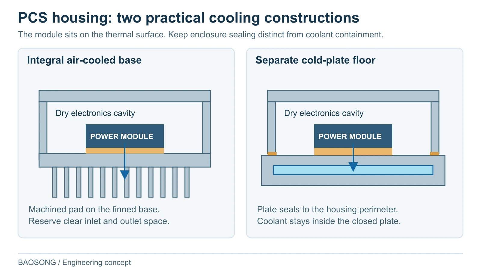
The module determines the thermal interface material and mounting method. Semikron Danfoss describes module-specific TIM patterns and a choice of grease or phase-change material. We use the selected module’s instructions to set the contact surface and fastener arrangement; a general-purpose gap pad is not a substitute for that specification.
Keep thermal, sealing and electrical surfaces distinct
We divide the housing drawing into functional zones: module contact pads, a continuous cover-gasket land, connector seating faces and specified conductive bonding points. Machining and finish notes are assigned to each zone. Thermal contact, sealing and electrical bonding do not automatically require the same surface treatment.
Place the busbar and terminal envelope above the module pads before adding internal ribs. Leave space for the specified electrical clearances, bolt tools and cable bends. We move or shorten a mechanical rib when it obstructs these areas, and support a loaded connector at its mounting wall rather than allowing the harness load to pull on the board.
The electrical designer supplies the required isolation, bonding and shielding details. We carry them into the housing geometry and finish drawing, including accessible bonding hardware and any specified conductive seam. Electrical and EMC acceptance then uses the completed equipment configuration.
Plan machining and finishing around the final interfaces
Use the module mounting plane as a reference for the nearby holes and connector positions. Support a thin base during machining, then measure it in the specified free or assembled condition. On a cast body, leave stock on the module pads and seal lands so those surfaces can be machined after the blank is produced.
Mark the approved finish or masking on the contact pads, gasket land, connector seats and bonding points before treatment. If a joined cooling base needs final machining, put that operation after the joining steps that could move the contact face. Protect the completed pads during packing so they reach assembly without handling damage.
Turn interface problems into manufacturing actions
| Customer problem | BAOSONG action | Customer result |
|---|---|---|
| Module runs hot despite a larger heat sink | Review contact, support, interface material and the external cooling boundary together. | A targeted contact or construction correction rather than adding fins without a usable heat path. |
| Cover or connector fit changes after finishing | Tie the module plane, openings, seal lands and finish state to common references. | Interfaces checked in the condition used for assembly. |
| Casting or machining route creates unstable local features | Review stock, tool access, workholding and critical surface sequence. | A route that controls functional features without unnecessary precision everywhere. |
| A coating conflicts with bonding or sealing | Identify functional zones, masking and hardware access before treatment. | Finish requirements matched to each interface’s purpose. |
| Transfer parts differ from the approved assembly | Compare drawing, material, route, cover, finish and inspection state. | Documented deviations and targeted re-verification. |
Define what the housing supplier verifies
BAOSONG defines the component inspection plan with the delivered mechanical scope. A dimensional inspection, assembled ingress test and electrical product evaluation answer different questions. Include the actual interfaces and configuration when deciding who performs each check.
| Question | Condition to agree | Evidence or handoff |
|---|---|---|
| Does the module fit and contact correctly? | Device drawing, datum, support state and specified interface. | Dimension/contact records for the finished housing. |
| Do cover and connectors meet their interface? | Gasket, hardware, connector parts and final finish. | Fit and closure checks on the agreed assembly. |
| Is the cooling path suitable? | Module losses, mounting, coolant or airflow and ambient boundary. | Thermal validation for the specified installed configuration. |
| Are electrical interfaces correctly prepared? | Isolation, bonding and shielding details from the electrical design. | Mechanical interface records and assigned electrical/EMC verification. |
| Is a coolant pressure boundary included? | Exact supplied assembly, seals, ports and approved test conditions. | Specified leak/pressure verification only where that scope exists. |
| Does enclosure protection meet the project? | Actual joints, penetrations and configuration. | Agreed assembled protection test, not a bare material claim. |
| Will repeat parts remain comparable? | Material, route, fixture, finish, joint and drawing revisions. | First-article baseline and change review. |
The public scope of IEC 60529, the IP Code concerns enclosure protection classification. It does not establish the inverter’s thermal capacity or electrical qualification. Select applicable product requirements with the responsible engineering team and keep the housing evidence linked to its actual role.
Two practical project pathways
Several lengths from one air-cooled section: keep the finned cross-section common and machine each variant’s module holes, connector openings and end closures. This can share extrusion tooling across a product family. Check the longest and most heavily loaded variant against its own airflow and loss conditions; a common section does not give every length the same thermal performance.
Transfer of an established cast housing: retain the accepted module pads, gasket path and connector arrangement. We compare the proposed casting and machining route with the current part, identify where stock or access must change, and quote the finished body against the agreed drawing. Any proposed geometry or finish change is shown for approval before it reaches production.
Make the production baseline represent the finished housing
For high-volume PCS inverter housing supply, agree the production route, critical stock, fixtures, treatment and inspection during quotation. An early machined sample can answer layout questions, but it does not validate a later casting or joint construction by itself. The representative first article follows the agreed production process.
Control changes to the module mounting plane, interface material specification, fins or cooler attachment, connector cutouts, cover hardware and surface zones. A small dimensional revision can change assembly or the thermal path. BAOSONG identifies which records need updating so the recurring part stays comparable with the approved baseline.
Why choose BAOSONG for your PCS inverter housing?
| Your priority | BAOSONG action | What you receive |
|---|---|---|
| A practical aluminum route | Match the section, local geometry and order pattern to extrusion, casting or machining. | A manufacturing recommendation with the reason and change conditions. |
| Module and terminal access | Locate contact pads, reserve the busbar envelope and place connectors where tools and cables can reach them. | Marked-up housing geometry with clashes identified before tooling. |
| Correct surfaces after finishing | Assign machining and finish notes to each contact pad, seal land and bonding point. | A surface-zone drawing and measurements of the specified finished features. |
| Stable repeat orders | Record the material, route, fixture references and finish used for the approved first article. | A traceable part specification for repeat orders and supplier transfer. |
We turn the existing module information into a manufacturing proposal. A drawing can move directly into quotation; a sample, layout or known fit problem can start the review while the remaining interfaces are clarified.
Request a PCS inverter housing quote
Send your PCS housing drawing, module layout or sample photo for a quotation. BAOSONG will confirm the included body, cover, cooler and hardware, then provide a formal price for your quantity and inspection requirements.
Frequently asked questions
What matters when sourcing a PCS inverter housing from China?
Compare the same module-level scope, drawing revision, material, construction, surface zones and inspection condition. Confirm whether the cover, seals, connector hardware and cooler are included. A generic outdoor cabinet price is not comparable with a finish-machined module housing.
Should I specify the alloy before the manufacturing route?
Use an approved material specification when one exists. For development work, select the product form, joining and functional requirements together before fixing the alloy and condition. A casting grade and an extruded section serve different manufacturing needs even when their finished outline is similar.
Can a sealed housing still be air-cooled?
Yes. Heat can pass through a designed base into exterior cooling surfaces while the electronics cavity remains closed. The device contact and the external airflow path still need validation. Venting the cavity is a different construction, not an automatic requirement for air cooling.
Must every order start with a prototype?
No. Approved drawings and established parts can proceed to manufacturing review and quotation. First articles, samples and qualification follow the project’s risk and order requirements; an unchanged recurring order is not treated as a new product design.
Send your drawing, module layout or sample
| Your starting point | BAOSONG next action | What you receive |
|---|---|---|
| Approved housing drawing | Review route, finished interfaces and acceptance. | A manufacturing quotation with proposed deviations. |
| Existing sample or assembly problem | Locate clashes, poor contact or inaccessible hardware in the module and cover arrangement. | Proposed pad, opening or mounting changes. |
| New module layout | Choose the body/cooler arrangement and place pads, connectors and the gasket path. | A recommended construction with the critical features marked. |
| Transfer or recurring supply | Compare the accepted part and process baseline. | A supply proposal with first-article and change requirements. |
Discuss your custom aluminum PCS inverter housing with BAOSONG. Send a drawing, module layout, sample photo or short project description.