
Quick answer: a custom machine vision camera housing
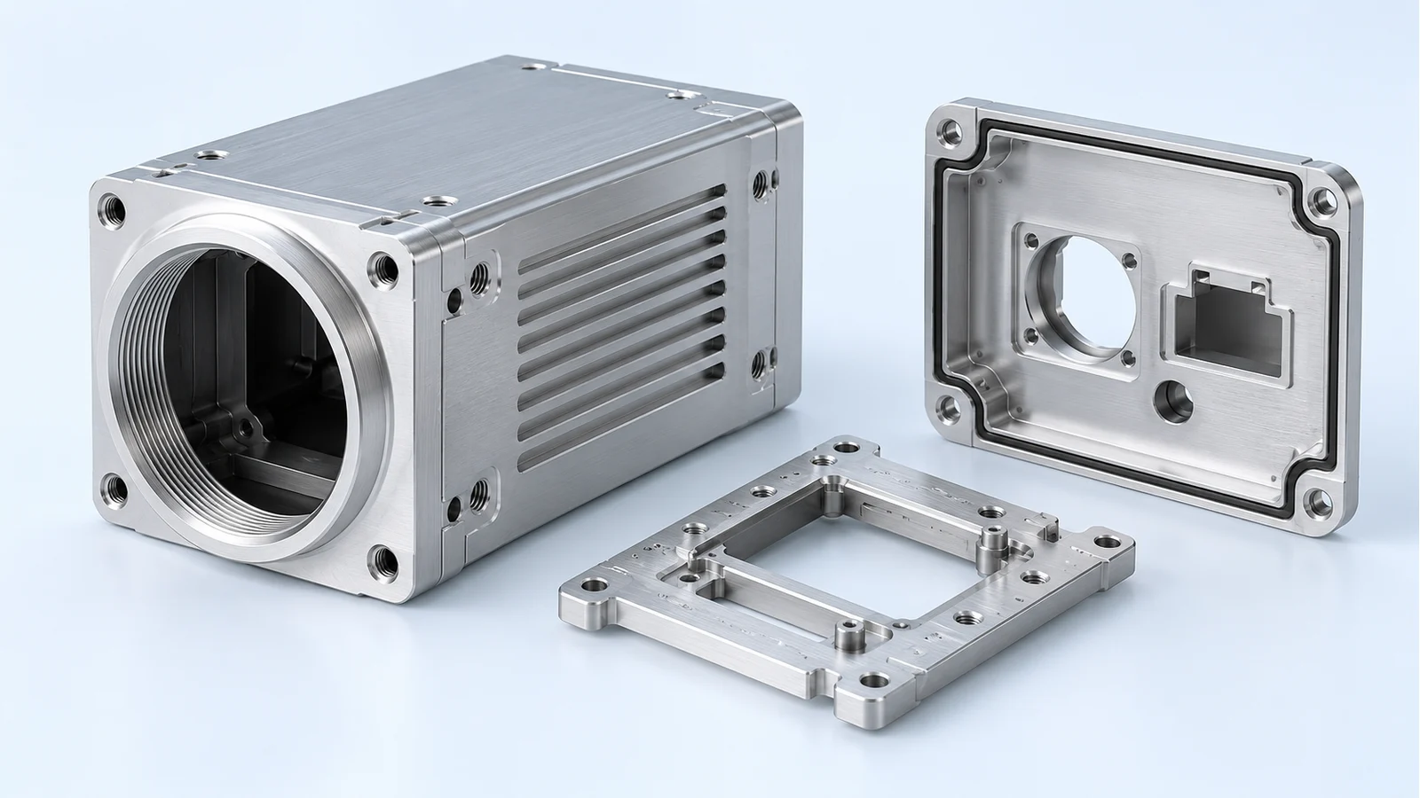
BAOSONG manufactures a custom machine vision camera housing around the lens, sensor and camera mounting references. We recommend a machined optical front or integral carrier when it shortens the locating chain. A separate rear cover can provide service access without disturbing those references; stable repeated bodies can also use extrusion or a cast blank with functional interfaces machined afterward.
An industrial camera aluminum housing combines a lightweight structure, machinable mounting features and a useful heat-conduction path. We coordinate lens access, sensor support, connector space, finishing and sealing with that structure. The manufacturing proposal defines the finished component and the additional imaging or environmental confirmation needed for the assembled camera.
Send your camera drawing, optical layout, sample photo or alignment and temperature problem. We will recommend the housing split and manufacturing route. Request your custom camera housing proposal.
At a glance: choose the housing construction
| Project condition | BAOSONG recommendation | Decision to settle |
|---|---|---|
| Lens and sensor geometry are changing | Machine an accessible optical front and located sensor carrier. | Lens reference, sensor plane and adjustment. |
| The optical chain must stay fixed during service | Separate the rear cover and connector access from that chain. | Locating versus service-retention features. |
| Several models share a repeated section | Compare extrusion with machined front and rear interfaces. | Section allowance, thermal contact and joint stack. |
| A stable shape integrates many features | Compare a cast blank with critical-interface machining. | Tooling, blank quality and final geometry. |
| An approved design is ready | Proceed directly to manufacturing and quotation review. | Finished state and component/assembly acceptance. |
Bare camera housing or protective enclosure?
A precision camera housing can locate the lens mount, sensor carrier and electronic assembly as part of the camera itself. That is different from a protective enclosure surrounding an already complete camera. BAOSONG’s custom bare-housing supply focuses on the drawing-based body, optical front, carrier, cover and agreed mechanical assembly.
These components fit our aluminum hardware for robotics and machine vision. A larger enclosure organizing several cameras, lighting and control equipment has another integration task. The bare camera body must preserve its own optical and mechanical references before the complete vision system is calibrated or tested.
Control more than the lens thread
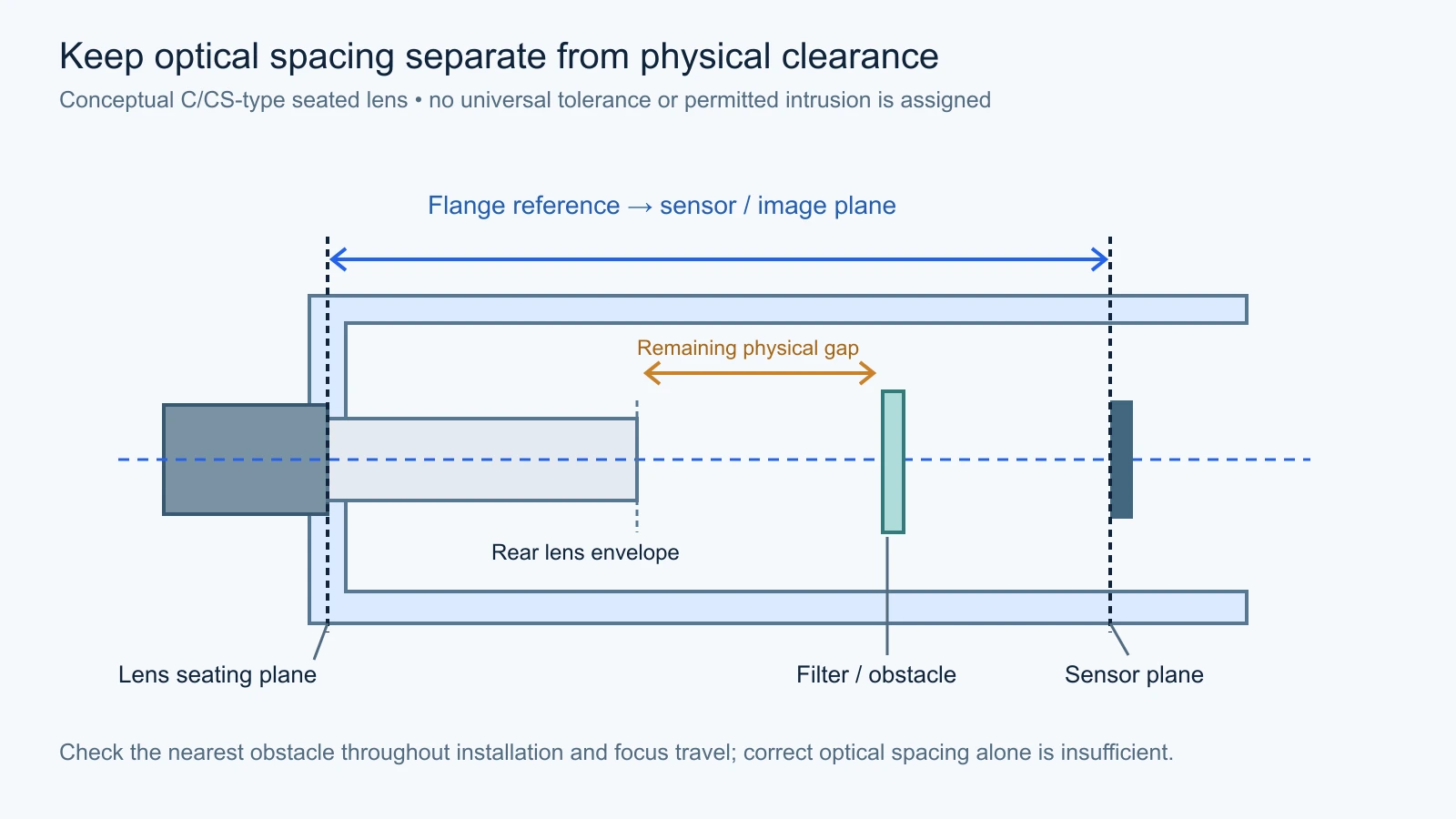
Identify the lens mounting plane, locating diameter or thread axis, sensor plane and camera mounting reference. Define the required distance, tilt and centering between them from the optical design. The required lens-to-sensor spacing, including the relevant flange focal distance or back-focus definition, follows the chosen lens and sensor assembly. The lens mount provides only part of that definition: a threaded lens that screws into the front can still have the wrong seating distance or rear clearance.
BAOSONG recommends a short, accessible locating chain. An integral optical front and sensor support can reduce separate interfaces when the assembly and machining access permit it. If a separate carrier allows useful adjustment or thermal isolation, locate and retain it deliberately and define how the final position is established.
| Mount and nominal reference | When we recommend it | Housing action |
|---|---|---|
| C-mount 1 inch, 32 TPI; 17.526 mm flange focal distance | A camera family using selected C-mount industrial lenses and a defined seating shoulder. | Machine the front reference and control the sensor position from it; check the selected lens’s rear envelope. |
| CS-mount Same thread; 12.526 mm flange focal distance | A design built around selected CS-mount optics and the shorter nominal mount-to-image-plane distance. | Use the CS reference stack. Do not reuse a C-mount front-to-sensor arrangement just because the thread matches. |
| S-mount / M12 M12 × 0.5; no universal flange focal distance | A compact board-camera layout with a selected lens, accessible focus adjustment and positive locking. | Define the holder position, focus travel and lock method from that lens; keep the moving rear envelope clear of the sensor and filter. |
These are nominal mount definitions from Edmund Optics’ lens-mount reference, not machining tolerances for your housing. Basler’s C/CS explanation also confirms the adapter direction: a 5 mm spacer can adapt a C-mount lens to a CS-mount camera; the reverse combination is not solved by that spacer. We check the actual lens, image plane and adjustment arrangement before releasing the front and carrier geometry.
Check the lens’s rear envelope against filters, the sensor and internal hardware throughout installation and adjustment. Basler’s lens-intrusion guidance makes clear that the allowed depth varies by camera and mount variant. We use the selected optical drawings rather than assigning one intrusion or flange-distance value to every custom camera.
Keep sensor location independent of uncontrolled assembly forces
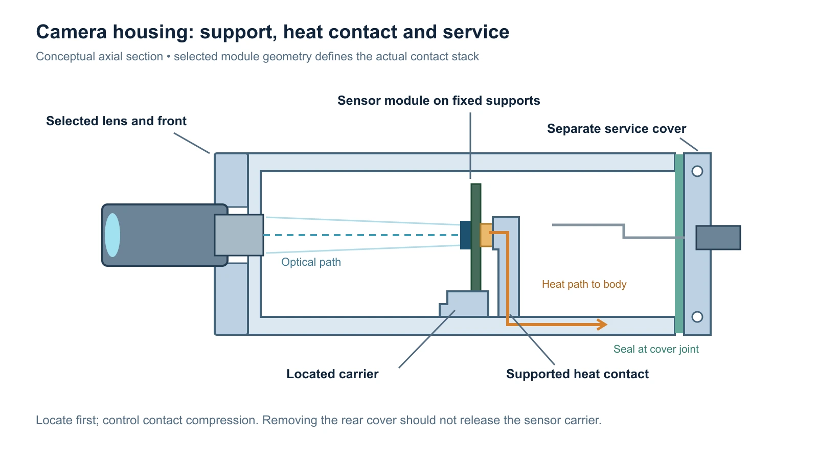
Define which surfaces or features locate the sensor module and which screws provide retention. A shimmed or adjustable carrier needs an accessible adjustment method, approved locking and a final record of the accepted configuration. Avoid using a flexible board edge as an undefined locating stop.
We review the support stack beneath the module, fastener access and the relationship to thermal pads or other contacts. Pad compression and cover tightening should not become uncontrolled sensor-position adjustments. Where the design needs controlled compliance, define the support and compression stack with the responsible electronics and optical engineers.
Reserve a removal path for the sensor module and connectors. A cover that can be removed without touching the optical carrier can simplify service. After any work that changes an optical reference, the assembled camera receives the relevant alignment or calibration confirmation.
Why use aluminum for the camera body?
Aluminum supports compact, lightweight housings with machined lens interfaces, module seats, connector openings and mounting features. It also gives the design a practical path for conducting heat from the camera assembly to the surrounding structure or cooling arrangement. These functions can be integrated without building the body from many separately aligned brackets.
For a machined front or carrier cut from plate, we recommend evaluating 6061-T651 as a practical starting material, with stock thickness, remaining section and finishing defined together. Kaiser’s engineering-plate specification provides a material-producer reference for that plate condition; it does not establish the stability of every finished camera part. An extruded or cast body needs its own suitable alloy, condition and machining allowance. Keep support around the optical front and mounting interfaces, and remove weight away from those load paths.
Design the heat path to the installed camera
Identify the heat sources, allowed temperatures, contact surfaces and final mounting arrangement. We propose a defined route from the relevant electronics or module interface to the aluminum body and then to the mounting structure, heat sink or airflow. A sealed cover around a camera is not automatically a cooling solution.
Basler’s heat-dissipation guidance recommends suitable conductive mounting and model-specific temperature checks. For your custom body, the contact, mounting and operating conditions belong in the assembly definition. We do not infer a temperature drop from a ribbed surface or the choice of aluminum alone.
Thermal and locating requirements must agree. A pad selected for heat transfer can also apply force to the board or carrier. We coordinate its supported area, compression and assembly stack with the optical references, then identify the installed temperature and alignment checks needed for confirmation.
Compare manufacturing routes for the finished housing
| Route and fit | Benefit and tradeoff | Selection / verification |
|---|---|---|
| Integral CNC body or optical front | Flexible lens and sensor interfaces with a short locating chain; internal access and removal need planning. | Recommended for evolving layouts and suitable repeat orders. Verify finished optical references. |
| Extruded body with machined ends | Useful for a stable repeated section; front, carrier and cover add interface relationships. | Select when section reuse is meaningful. Inspect the completed stack rather than the raw profile alone. |
| Cast blank with functional machining | Integrates suitable bosses, ribs and connector areas; adds tooling and blank-quality requirements. | Compare for stable geometry and an order plan. Define critical machining allowances and finish. |
Choose the assembly split separately from the blank process. An integral front and carrier can shorten the optical chain; a separately located carrier can provide useful adjustment or module interchangeability. A removable rear cover supports connector service in either arrangement. These are architecture choices that can be combined with CNC, extrusion or casting, not a fourth competing production process.
Our custom aluminum CNC machining turns the selected construction into the required interfaces. CNC can remain the recurring supply route. Approved drawings proceed directly to manufacturing review; a change of supplier does not require a new optical concept phase.
Have a lens and board selected but no finished housing drawing? Send the lens model and board layout. BAOSONG will propose the optical front, supported carrier and service-cover split, with the critical dimensions identified for your design review.
Separate optical, thermal, sealing and service functions
Plan the reference surfaces through machining and finishing. Where a cover or carrier needs another setup, define how its datums transfer back to the working optical chain. Thin walls require support without forcing a distorted body into apparent agreement with the drawing.
Define the window and seal interface from the selected components, media, environment and retention method. Include the connector, cover, cable entry and any vent within the environmental boundary. A machined O-ring groove is one feature in that boundary, not proof of a finished camera’s ingress-protection rating.
Keep connector installation and strain relief accessible. Support cable reactions so they do not disturb a delicate optical reference, and provide service access without uncontrolled movement of the front or carrier. BAOSONG proposes the housing split and functional zones together.
Specify useful light control and clean assembly
Assign finish by function: optical cavity, lens fit, sensor locating surface, thermal contact, ground, seal and visible exterior. A dark cosmetic finish does not by itself establish spectral reflectance, stray-light suppression or a clean optical cavity. Define any optical coating or texture requirement with a suitable acceptance method.
Our aluminum surface-finishing planning coordinates masking and final machining with those zones. Deburr accessible internal edges and protect the optical cavity from chips, abrasive media and handling contamination. Packaging should protect mounting faces and keep the delivered revision identifiable.
How BAOSONG resolves camera housing problems
| Problem | BAOSONG action | What you receive |
|---|---|---|
| Focus changes after the housing is assembled | Trace lens seating, sensor support and final stack. | A functional-reference and final-state check proposal. |
| One image corner behaves differently after tightening | Review specified tilt, supports and fastener-induced movement. | A targeted interface or support improvement. |
| The body runs hot inside a sealed installation | Review the actual contact and installed heat-rejection path. | A thermal-interface manufacturing proposal. |
| Rear service disturbs camera alignment | Separate removable access from the optical locating chain. | A serviceable cover/carrier arrangement. |
| A black finish is assumed to solve optical reflections | Separate cosmetic color from the specified optical surface behavior. | A defined finish and relevant acceptance requirement. |
Define housing evidence and imaging confirmation
For each mechanical requirement, agree how the references are established and whether the feature can be reached by a suitable dimensional method. Define the finished support and assembly condition, with measurement capability appropriate to the tolerance. Optical acceptance uses the selected lens, sensor, target and imaging conditions; it answers a different question from checking the machined carrier.
Our component inspection planning connects the accepted drawing to methods, conditions and records. Mechanical geometry supports imaging performance, but a dimensional report does not replace the complete camera’s optical, thermal or environmental evaluation.
| Requirement | Condition / record | Separate confirmation |
|---|---|---|
| Lens-to-sensor mechanical references | Final datums, distance, orientation and location as specified. | Assembled focus, alignment and image-quality checks. |
| Lens intrusion and installation access | Selected lens envelope, filters, internal hardware and insertion path. | Representative optical assembly trial. |
| Thermal contact and support | Defined material, contact surfaces and assembled compression stack. | Installed operating temperatures and alignment stability. |
| Seal, window and connector features | Approved component geometry, finish, retention and delivered scope. | Specified complete-assembly environmental test. |
| Cavity finish and cleanliness | Functional zones, contamination limits and packaging. | Optical surface behavior under the relevant imaging conditions. |
Two practical OEM camera projects
Illustrative new compact vision camera. The team has selected a lens and sensor module but is changing the connector position. We recommend a machined optical front and located carrier, with a separate service rear. The proposal fixes the functional references and preserves installation and thermal-contact access.
Illustrative recurring camera family. Several models share a body section and mounting arrangement. We compare a repeated extruded body with the current machined route while retaining model-specific fronts and carriers. The accepted comparison includes the completed optical stack, finishing, service and first-article evidence.
Keep the accepted optical stack consistent in repeat supply
High-volume machine vision camera housing supply needs a representative first article using the intended material, blank, machining, finish and inspection route. Machine vision camera housing mass production must preserve the accepted functional references and assembly state, including controlled carrier or shim revisions.
BAOSONG reviews changes to the front interface, carrier retention, coating, thermal contacts, connector opening and seal arrangement against their effects. A revision can change imaging or temperature behavior without changing the outside envelope. We identify the affected component checks and the required assembly confirmation before release.
Why choose BAOSONG for custom camera housings?
| Your priority | BAOSONG action | What you receive |
|---|---|---|
| A stable optical locating chain | Coordinate lens front, sensor carrier and camera mount. | A critical-feature and final-state map. |
| A practical aluminum construction | Compare access, support, blank and service split. | A recommended manufacturing route. |
| Heat and sealing integrated with geometry | Coordinate contact, covers, windows and connectors. | A defined functional-zone and assembly proposal. |
| Consistent recurring components | Establish representative inspection and change controls. | An accepted first-article and supply baseline. |
Request a custom camera housing quote
BAOSONG provides a formal quotation after reviewing your drawing or requirements, optical and module interfaces, material, finish, quantity and inspection scope. Send the information available; we will clarify the remaining conditions for a focused proposal.
Frequently asked questions
What should I compare when sourcing a camera housing from China?
Compare the same revision, supplied body/carrier/cover scope, material condition and finished references. Agree which mechanical features are inspected and which optical or environmental results need complete-assembly confirmation. A protective box and a precision bare camera body are different purchases.
Can one body serve several lens or sensor variants?
We recommend a shared body when the mounting envelope, heat path and service access remain useful across the family. Use model-specific optical fronts or located carriers where the lens seating and sensor stack differ. Identify each combination by revision and confirm its optical references rather than forcing every variant into one fixed front-to-sensor distance.
What changes when a protective window or filter is added?
Provide the selected element’s drawing and optical requirements. BAOSONG will define its seat, retention, sealing and installation clearance, and check access against the lens and sensor assembly. The optical design review also checks the added element’s effect on imaging. Agree the complete assembly’s environmental test with the window, connector and seal configuration included.
Start with your camera layout or housing issue
| What you have | BAOSONG next action | What you receive |
|---|---|---|
| Approved housing drawing | Review functional machining, finish and acceptance directly. | A drawing-based quote and stated deviations. |
| Optical/module layout | Recommend front, carrier and service-cover construction. | A manufacturing proposal and priority interfaces. |
| Existing focus, heat or assembly issue | Trace references, support and delivered state. | A targeted component improvement plan. |
| Transfer or recurring demand | Compare the accepted stack and intended route. | A representative first-article and supply proposal. |
Discuss your custom machine vision camera housing with BAOSONG. A drawing, layout, sample photo or short problem description is enough to begin.