
Quick answer: which aluminum components make up an EV battery enclosure?
An EV battery enclosure can combine extruded perimeter rails and crossmembers, a formed or fabricated lower tray, a sheet or cast top cover, cast corner nodes, CNC-machined mounting and sealing interfaces, coolant plates or manifolds, shields, brackets and joining hardware. Each component should be designed from its load path, sealing boundary, thermal role, electrical interface and manufacturing route.
Do not specify the complete enclosure as “aluminum” and expect one alloy or process to satisfy every function. The perimeter may need controlled crash deformation and weld performance; a cover may prioritize stiffness and sealing at low mass; a cold plate must contain coolant and distribute heat; a machined interface must hold final datums, gasket geometry and mounting accuracy.
Flow vehicle and pack requirements down to each supplied component, then define how component evidence supports system validation. A material certificate, dimensional report or leak test proves only its stated scope. Regulatory and OEM approval remain pack- or vehicle-level activities unless the project assigns a specific component test and acceptance boundary.
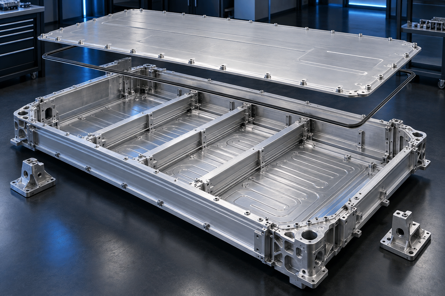
Start with the enclosure architecture and load paths
Use this five-step order before selecting an alloy or manufacturing process:
- Define the system boundary. Record the pack envelope, vehicle mounts, service access, environmental boundary, cooling connections and target markets.
- Map the load and leak paths. Show how crash, road, lifting, module, coolant and sealing loads pass through rails, panels, joints and fasteners.
- Give each component one clear responsibility. Identify its structural, thermal, sealing, electrical, corrosion and assembly functions.
- Select the production route. Compare extrusion, sheet fabrication, casting and CNC machining against section shape, quantity, tooling, joining and inspection.
- Assign evidence before release. State which material, component, subassembly, pack and vehicle tests prove each requirement and who owns them.
The enclosure is a structural, environmental and assembly system around a rechargeable energy storage system. Depending on the vehicle architecture, it may also contribute to body stiffness, underbody protection and crash-load transfer. Decide first whether the pack is attached to the body, integrated into the body structure or designed as another project-specific architecture.
Map the load paths for vertical support, side impact, pole intrusion, curb strike, road debris, lifting, towing, jacking where applicable, module restraint, pressure events and vehicle mounting. Identify which rails, crossmembers, corner joints, bottom panels and fasteners carry each load. A strong local bracket cannot correct a discontinuous system load path.
SAE’s battery-enclosure engineering overview describes the pack box as a vehicle-integration problem involving structure, mass, manufacturing and safety tradeoffs. Use such industry context to frame questions, then apply the actual OEM load cases, design allowables and validation plan.
Assign a clear job to every aluminum component
| Component | Primary functions | Typical manufacturing routes | Evidence to plan |
|---|---|---|---|
| Perimeter rails | Crash load transfer, intrusion control, sealing support and vehicle attachment | Extrusion, forming, CNC machining and joining | Section dimensions, material state, joint properties and component load tests |
| Crossmembers | Module support, span reduction, local stiffness and load distribution | Extrusion, roll forming, stamping, machining and joining | Position, straightness, joint quality and defined stiffness/load checks |
| Lower tray or bottom panel | Environmental boundary, underbody interface and distributed support | Sheet forming, fabrication, extrusion panel, casting or hybrid construction | Form, seams, flatness, coating, impact strategy and leak boundary |
| Top cover | Closure, service access, sealing, pressure response and barrier integration | Formed sheet, fabricated sheet, casting or composite hybrid | Flange geometry, fastener pattern, deflection, seal compression and vent strategy |
| Cast nodes and brackets | Load-path transitions, feature integration and mounting | High-pressure or other qualified casting process plus CNC | Porosity criteria, datums, joint zones, fatigue and local strength |
| Cold plate and manifolds | Heat transfer, coolant distribution and pressure containment | Machining, extrusion, roll bonding, forming, brazing or welding | Flow, pressure drop, cleanliness, leak, burst, corrosion and thermal-cycle evidence |
| Machined interfaces | Datums, seals, ports, fastener seats and vehicle mounts | CNC milling, drilling, boring, tapping and finish machining | Final-state dimensions, GD&T, surface texture and traceable inspection |
This allocation prevents one supplier drawing from inheriting vague system-level requirements it cannot verify. It also reveals which components should be combined to reduce joints and which should remain separate for service, sealing, process access or crash replacement.
Design extruded rails and crossmembers around the section
Extrusion suits long components with a constant cross-section. Closed cells, ribs, flanges, bolt channels, weld lands and locating features can be integrated into perimeter rails or crossmembers. The section can place material along load paths while reducing separate brackets and fasteners.
Start with the structural envelope, load direction, joint access, die constraints and quench/temper capability. Avoid abrupt wall changes, inaccessible pockets and features that cannot be supported by a practical die. Establish which surfaces remain as-extruded and which require CNC machining for mounts, gasket interfaces or alignment.
For crash-relevant parts, do not infer component performance from catalog tensile strength. Section geometry, material direction, temper, weld heat-affected zones, joint continuity, strain rate and collapse mode all matter. Validate the extruded member and the joined assembly against project load cases.
Review aluminum extrusion services for manufacturing context and custom extrusion design for profile-development inputs. Product-form tolerances and later machined-feature tolerances should be called out separately.
Choose tray and cover construction from area, depth and sealing
Large shallow panels may favor sheet forming, stamping, roll forming, extrusion panels or fabricated constructions. Deeper trays or highly integrated geometries may lead to casting or hybrid solutions. The decision depends on blank size, draw depth, wall transitions, joining length, expected quantity, tooling investment, stiffness and the required leak boundary.
Use beads, section depth, local reinforcements and crossmembers to manage panel stiffness before adding uniform thickness. Provide controlled flange width around the perimeter seal, and keep forming transitions, weld terminations and fastener bosses from disturbing the sealing land.
A removable cover needs a repeatable fastener pattern, compression control and service plan. A welded closure changes access and repair. Pressure-relief devices and vent paths require their own system engineering; a thicker cover is not a substitute for a defined pressure-management strategy.
Aluminum sheet-metal fabrication can support trays, covers and shields where the formed geometry, seams and inspection plan match the design.
Use cast nodes where integration justifies the process
Castings can combine corner transitions, mounts, bosses, ribs, ports and joint interfaces in a near-net component. They can reduce part count, but introduce tooling, filling, solidification, porosity and heat-treatment considerations that differ from wrought products.
Place critical machined datums and sealing faces with enough stock and stable support. Separate pressure-tight, fatigue-critical, crash-critical and cosmetic requirements so the casting process and inspection plan can address each. Avoid thin-to-thick transitions and isolated heavy sections that create difficult feeding and shrinkage conditions.
If a cast node joins to extruded rails or sheet panels, validate the complete material and joint combination. Alloy chemistry, surface condition, joint heat, distortion and galvanic exposure can influence the result. Aluminum die casting is one possible route for repeat-volume integrated components, subject to drawing review and process qualification.
Reserve CNC machining for functional interfaces
CNC machining is useful for vehicle mounts, module datums, sealing grooves, ports, threaded features, locating bores and post-joining correction. It also supports prototypes before production tooling is justified. Machining the entire tray from solid may create unnecessary material loss and cycle time when most geometry can be extruded, formed or cast.
Define datums that represent assembly function. Locate sealing flanges, coolant ports, mounting holes and module interfaces from a coherent reference system. Avoid independent coordinate dimensions that allow individually conforming features to assemble poorly.
Plan how welding, heat treatment and coating occur relative to final machining. A surface machined before a long weld can move afterward; a bore finished before coating may change in final condition. State the inspection state and any protected or masked areas.
Precision aluminum CNC machining can supply local accuracy, but practical tolerances depend on component size, wall stiffness, access, material condition, fixturing, process sequence and measurement method.
Integrate cooling plates without merging test boundaries
A cold plate may be structural, attached to the tray or supplied as a separate pressure component. Its flow channels, cover joint, ports and thermal-interface surface must be designed together. Machined, extruded, brazed, roll-bonded and formed constructions use different aluminum product forms and joining mechanisms.
Define coolant composition, concentration, temperature range, operating and test pressures, heat-load map, flow range, pressure-drop limit, cleanliness and allowable leakage. Then evaluate temperature uniformity, local hot spots, deformation, corrosion, fatigue, joint integrity and port loads.
Keep three boundaries distinct: the coolant circuit, the environmental enclosure and the complete pack. A cold-plate leak test does not prove pack ingress protection. A pack water test does not prove internal coolant-channel integrity. Each needs its own method, state and acceptance criteria.
Material selection for the cold plate should follow the fabrication route and joint cycle. Bulk thermal conductivity alone cannot predict the system temperature because interface material, contact pressure, channel layout, flow and heat rejection also contribute.
Design joints as part of the load and seal architecture
Possible joining routes include arc or laser welding, friction stir welding, brazing, mechanical fasteners, self-piercing rivets, flow-drill screws, structural adhesives and hybrid combinations. Select the route from materials, access, heat input, joint loads, sealing, corrosion, service and production rate.
Heat can distort long rails and flanges and can change local material properties. Parent-metal data should not be used as the joint allowable without a qualified basis. Define weld sequence, restraint, inspection access and the point at which critical surfaces receive final machining.
Adhesive joints need controlled surface preparation, bond-line geometry, cure and environmental validation. Fasteners need bearing, pull-out, preload and isolation analysis. Hybrid joints require a clear explanation of which element carries load, which seals, and how differential expansion is managed.
Coordinate these decisions with aluminum welding and fabrication before cross-sections and access close around the joint.
Protect sealing flanges from accumulated variation
The seal depends on the flange, cover, gasket or adhesive, fastener pattern and joint stiffness. Control flange flatness, surface texture, steps at joined segments, porosity or weld interruptions, coating condition and local deflection. State the datum and measurement method used in the final assembly state.
Use a tolerance stack to evaluate minimum and maximum seal compression across the complete perimeter. Corners, connector cutouts, rail splices and cover transitions deserve focused review because local stiffness and geometry can change rapidly.
Define the leak or ingress test boundary, preparation, pressure or exposure, duration, temperature and acceptance rule. ISO 20653:2023 defines IP-code degrees of protection for road-vehicle electrical equipment against foreign objects, water and access; it does not assign a required rating to every battery pack. The OEM and target-market requirements determine the applicable condition. For the United States, begin with NHTSA’s current electric- and hybrid-vehicle safety overview and confirm the requirements that apply to the vehicle program.
Control corrosion and electrical interfaces together
An enclosure can contact steel vehicle structures, stainless fasteners, copper conductors, carbon-containing materials, coolant and road contaminants. Map every dissimilar-metal junction, drainage path and coating interruption. Trapped electrolyte in a crevice may govern durability more than the open aluminum surface.
Choose conversion coatings, paint, anodizing, sealants, isolation washers or other protection from the complete material couple and environment. Protect bare edges and repair zones according to the approved system. Validate surface preparation and coating adhesion on production-representative material.
Grounding and electromagnetic functions may require controlled conductive contacts, while other areas require electrical isolation. Mark both on the drawing and verify the assembled electrical path. Do not leave coating removal to an undocumented shop-floor decision.
Treat crash and thermal events as system validations
The enclosure contributes to mechanical protection and thermal-event management, but no aluminum component alone certifies the rechargeable energy storage system. Cell behavior, module spacing, barriers, detection, controls, venting, vehicle structure and occupant protection work together.
UN Global Technical Regulation No. 20 addresses electric-vehicle safety, including rechargeable energy storage system performance. UN Regulation No. 100, 03 series covers vehicle approval requirements for electric power trains in the markets that apply it. For a concrete example of a regulated verification procedure, review NHTSA’s official FMVSS 305 laboratory test procedure; do not assume that a test procedure for one market proves approval in another.
ISO 6469-1:2019 specifies safety requirements for the RESS and has a 2022 amendment concerning thermal-propagation safety management; ISO lists a revision under development. Use the released edition and applicable amendment required by the project, and separately monitor future changes. The U.S. Department of Energy’s work on materials and component testing protocols also shows why the test level, specimen and evidence owner must be defined explicitly.
UL Solutions’ EV battery testing overview illustrates how applicable standards vary by region and program. Confirm the current regulatory market, vehicle category, OEM specification and responsibility matrix before component design is frozen.
Build a requirement-to-evidence matrix
| Requirement | Component control | Component evidence | System evidence |
|---|---|---|---|
| Crash and intrusion | Material state, section, joint and load-path interfaces | Certificates, coupons, joint tests and component load tests | Pack or vehicle simulation and physical tests |
| Environmental sealing | Flange geometry, seams, coating and connector interfaces | Dimensional and defined subassembly leak checks | Complete pack ingress or leak validation |
| Cooling | Channels, ports, flatness, cleanliness and joint integrity | Flow, pressure, leak and thermal characterization | Pack thermal performance across operating conditions |
| Corrosion | Alloy, coating, isolation, drainage and repaired areas | Process records and component coupons/tests | Assembly exposure with real material couples |
| Electrical protection | Coating, grounding pads, isolation features and clearances | Dimensions and interface resistance/continuity where specified | Pack and vehicle electrical safety validation |
| Thermal event | Barrier supports, vents, joints and material response | Defined material or component screening | RESS or vehicle thermal-propagation assessment |
The matrix prevents a component report from being presented as system approval. It also helps sourcing teams request the evidence that a supplier can actually produce and identify tests that belong to an accredited laboratory, battery integrator or vehicle OEM.
Control datums, distortion and final inspection state
Large aluminum assemblies can move through forming, welding, heat treatment, machining, coating and seal installation. Build the datum structure around vehicle mounts, module interfaces, cover seal and coolant connections. Identify which characteristics are measured at component, subassembly and finished-enclosure stages.
Use fixtures that support the part without forcing it into conformance during measurement. Document temperature, restraint and assembly condition for flexible panels and long rails. A free-state measurement and a bolted-state measurement answer different questions.
Connect material certificates, extrusion or casting lots, weld records, coating batches, leak tests and dimensional reports through traceability. The BAOSONG quality overview describes general inspection support; specific methods, sampling and records must be agreed for the project.
Plan the prototype-to-production transition
A CNC-machined prototype can confirm packaging, mounting, sealing geometry and early thermal concepts, but it may not reproduce the material direction, joints, residual stress, wall thickness or crash mode of a production extrusion, stamping or casting. Record which results transfer and which require new validation.
Before production release, build parts from representative material, tooling, fixtures, joining, coating and inspection. Use first articles to validate fit and evidence flow. Then define change-control triggers for alloy source, temper, die, casting tool, weld program, adhesive, coating, machining fixture and inspection method.
Tooling investment should follow stable requirements. A profile die, stamping tool or casting die can reduce unit processing at volume, but late changes to seal geometry, port location or crash section can erase that advantage.
A practical EV battery-enclosure component workflow
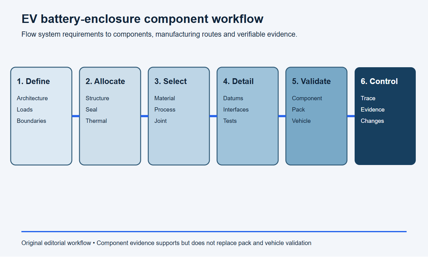
- Define architecture. Establish the pack boundary, vehicle interfaces, load paths, environmental boundary, cooling and service concept.
- Allocate functions. Assign structural, sealing, thermal, electrical and assembly jobs to each aluminum component.
- Select routes. Match extrusion, sheet fabrication, casting, CNC and joining to geometry and expected production.
- Detail interfaces. Control datums, joints, seal flanges, coolant ports, coatings, grounding and inspection state.
- Validate by level. Separate material, component, subassembly, pack and vehicle evidence.
- Release and control. Preserve traceability, first-article results, process records and change approval.
RFQ checklist for aluminum battery-enclosure components
Copy the following request into the RFQ and replace the bracketed fields. Attach the controlled 2D drawing, 3D model and requirement matrix rather than relying on the text alone.
RFQ scope: Please quote [component name and revision] for [prototype quantity] and [annual volume]. The component forms part of an EV battery enclosure and is responsible for [structural / sealing / thermal / electrical / assembly functions]. Quote the specified [alloy, temper and product form], the proposed manufacturing and joining route, tooling, unit price, lead time and production capacity. Identify every requested deviation.
Required evidence: Include material traceability, dimensional inspection against [drawing revision], special-process records, [leak / pressure / joint / coating / cleanliness] results, first-article documentation and the proposed change-control process. State which requirements need pack- or vehicle-level validation and are outside the component supply scope.
- component boundary and responsibility matrix;
- 2D drawing, 3D model and interface-control data;
- alloy, temper, product form, applicable material standard and substitution rules;
- load cases, stiffness, fatigue and crash/intrusion role;
- datum system, final-state dimensions, GD&T and surface requirements;
- joining route, qualified joint properties and distortion controls;
- seal system, flange requirements and leak/ingress test boundary;
- coolant, thermal map, flow, pressure, cleanliness and corrosion conditions;
- coating, galvanic isolation, grounding and electrical interfaces;
- prototype and production quantities, tooling and expected ramp;
- inspection, traceability, report format and change-control requirements;
- pack- and vehicle-level requirements that flow down to the component.
Stop conditions: the component is not ready for release
Pause tooling or production release if any item below is unresolved. Closing these points before the purchase order is usually less expensive than correcting a large welded or sealed assembly after first articles.
- the component boundary, load path or owner of a pack-level requirement is unclear;
- the drawing does not define a coherent datum system and final inspection state;
- seal compression, flange flatness or the leak-test boundary has no measurable acceptance rule;
- parent-metal properties are being used for a weld, brazed joint or adhesive joint without representative evidence;
- coolant chemistry, operating range, proof pressure, cleanliness or allowable leakage is missing;
- dissimilar-metal contacts, grounding points or coating interruptions have no corrosion-control plan;
- prototype construction differs from the intended production route and the validation gap is not recorded;
- the supplier cannot identify required certificates, inspection records, traceability or change-notification triggers.
Frequently asked questions
Which aluminum components are usually extruded?
Perimeter rails, crossmembers, channels and some cooling profiles are common candidates because they have long constant sections. Final suitability depends on die feasibility, material state, section tolerances, joining, crash behavior and required machining.
Should an EV battery tray be one piece?
There is no universal answer. A one-piece construction may reduce seams, while a multi-piece or hybrid design may improve manufacturability, repair, tooling, local material placement or joining access. Compare the complete load, seal, process and validation plan.
Can CNC machining hold all final enclosure dimensions?
CNC can finish critical local interfaces, but large flexible assemblies still depend on forming, welding distortion, fixture strategy, datum transfer and measurement state. Machine only where the function and tolerance justify it.
Does an IP rating prove the coolant plate does not leak?
No. Ingress protection addresses the defined external enclosure exposure. The coolant circuit is a separate pressure boundary and requires its own leak, pressure and durability tests.
Can a component supplier certify the complete battery pack?
Only if the contract, accreditation and validation scope explicitly assign that responsibility. Component evidence normally supports, but does not replace, RESS and vehicle-level testing.
What should be reviewed before tooling release?
Freeze architecture, interfaces, material and joining route, seal and cooling boundaries, critical tolerances, test responsibilities, representative-process validation and change-control rules before committing profile, forming or casting tooling.
Request an EV battery-enclosure component review
BAOSONG can review aluminum rails, trays, covers, nodes, machined interfaces and cooling components for manufacturability within the supplied drawing and requirement scope. Send the component models, material callouts, quantities, joint plan and required evidence through contact us for a project-specific review.
Recommended Downloads for Aluminum Alloy Selection
Use these BAOSONG references to compare alloy families, temper conditions, machinability, strength, corrosion resistance and design implications before quotation.
- Aluminum Alloy Comparison Chart (editable Excel)
- Tolerance Reference Guide (PDF)
- Aluminum CNC Machining Design Guide (PDF)
- Aluminum Part Design Checklist (editable Excel)
Need help choosing an alloy or temper for your application? Contact BAOSONG Precision.
