
Quick answer: what is a practical CNC machining tolerance for aluminum?
A practical production tolerance is the widest tolerance that protects the part’s fit and function across the full batch. It is assigned to a specific feature, relative to defined datums, in a stated material and inspection condition. There is no responsible single tolerance for every aluminum CNC part.
A drawing may apply general tolerances to noncritical dimensions and tighter requirements to selected bores, faces or locations. The practical value depends on feature size, tolerance span, alloy and temper, stock condition, setups, finishing and the agreed measurement method. Large plates, thin walls, long-reach features and dimensions spanning multiple setups can make the same numerical requirement much harder to sustain.
The production question is therefore not “Can a machine hit ±0.01 mm once?” It is “Can the agreed process produce and verify every specified feature through the accepted batch, including finishing and environmental effects?”
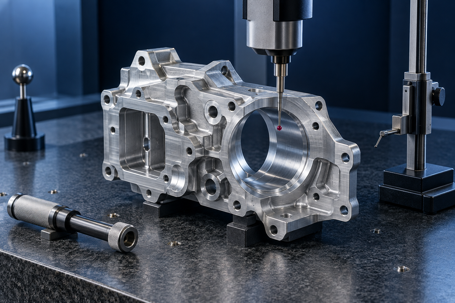
Seven-step tolerance review
| Step | Action | Required output |
|---|---|---|
| 1 | Identify the fit, seal, alignment, motion or load function | Critical feature list |
| 2 | Select functional and measurable datums | Datum reference plan |
| 3 | Assign size, form, orientation, location or texture controls | Feature-level requirements |
| 4 | Review stock, wall thickness, access and setup sequence | Manufacturing risk list |
| 5 | Define as-machined or finished acceptance condition | Clear inspection stage |
| 6 | Agree measurement method and decision rule | Inspection plan |
| 7 | Run a first article and review production data | Released tolerances and process |
Do not treat four different specifications as one tolerance
| Specification | What it controls | Example buyer question | Typical verification approach |
|---|---|---|---|
| Size tolerance | The permitted variation in a feature of size or another dimension. | Will this shaft or bore achieve the intended fit? | Micrometer, bore gauge or suitable dimensional system. |
| Geometric tolerance | Form, orientation or location relative to defined references. | Will the hole pattern align after assembly? | Fixture, CMM or another method matched to the characteristic. |
| Surface texture | The specified characteristics of a surface profile. | Does the sealing or sliding face need a defined finish? | Applicable surface measurement method and parameter. |
| Machine specification | A property of the equipment under stated test conditions. | What can the machine position or repeat during its own test? | Machine performance test—not finished-part acceptance. |
Step 1: prepare the tolerance inputs
Before reviewing numbers, collect:
- the assembly function and mating-part information;
- the 2D drawing and 3D model with matching revisions;
- alloy, temper and starting stock form;
- free-state or restrained acceptance condition;
- machining and finishing sequence;
- prototype, batch and repeat quantities;
- required first-article or production inspection records;
- the drawing, GD&T and decision-rule standards that apply.
Mark unknown items and assign an owner. Do not fill them with a supplier’s default tolerance block.
A machine’s positioning accuracy does not automatically become the tolerance of a finished part. Cutting forces, tool wear, workholding, thermal change, stock condition, tool access and inspection all sit between programmed motion and an accepted component.
Start with function, datums and the acceptance condition
A drawing should tell manufacturing and inspection what matters. ASME describes Y14.5-2018 (R2024) as establishing symbols, rules, definitions and practices for dimensioning and tolerancing. If your project uses another GPS or company standard, identify that system and edition instead of mixing conventions.
Use this sequence for critical aluminum features:
- State the function. Identify the fit, seal, alignment, motion or load path that can fail.
- Select stable datums. Use features that locate the part in its assembly and can be accessed during manufacturing and inspection.
- Control the needed characteristic. Size alone may not control location, orientation or form.
- Define the condition. Clarify whether acceptance applies as machined, after anodizing or in another finished state.
- Agree how conformance is decided. Match the method and measurement uncertainty to the tolerance and risk.
NIST’s work on uncertainty and dimensional calibrations explains why calibration, environment and measurement method influence confidence in a result. ASME B89.7.3.1 likewise addresses decision rules when measurement uncertainty affects acceptance or rejection. This is especially important when a reported value sits near a specification limit.
A practical tolerance map for one hypothetical part
The diagram below shows how an engineering review can divide a part into functional classes. The numbers are deliberately omitted: the correct values depend on the mating parts, loads, size, material condition and verification plan.
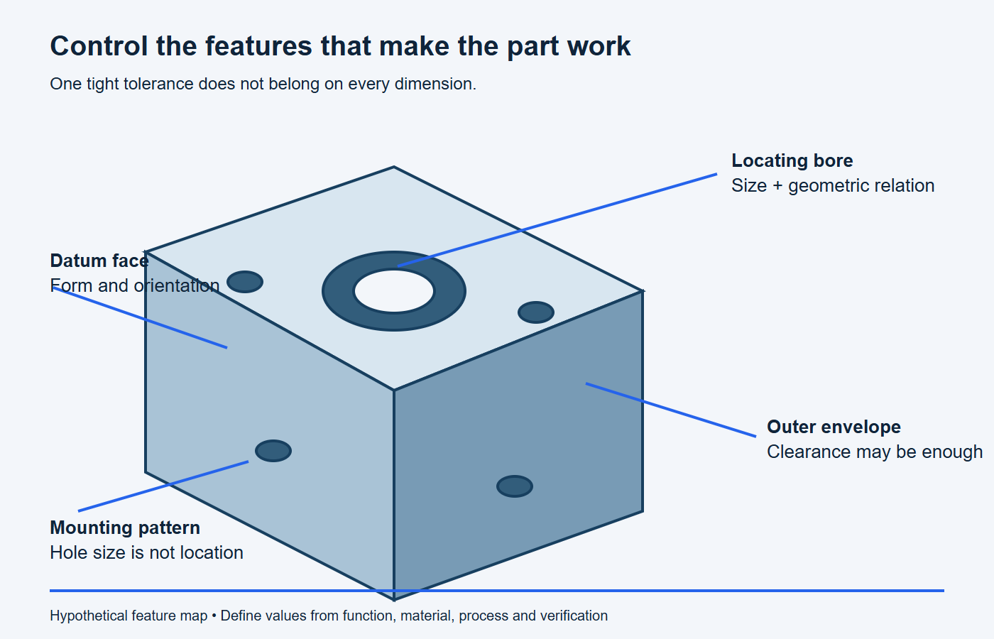
Consider an optical-sensor housing:
- The locating bore controls the relationship to the sensor and needs a size and geometric requirement appropriate to that fit.
- The mounting face establishes a datum and may need form control if it affects alignment.
- The bolt holes need enough positional control for assembly, but their size tolerance should not be confused with the location of the pattern.
- The external envelope may only need clearance. Tightening it to the same level as the locating bore may add inspection and machining effort without improving function.
This is the kind of feature-level discussion to have during a drawing and engineering review. It produces a clearer quotation than a note saying “all dimensions ±0.01 mm.”
What makes a tolerance harder to hold in production?
Part size and tolerance span
A short distance within one setup is a different problem from the relationship between features at opposite ends of a long component. The larger span increases sensitivity to stock condition, temperature, support and measurement strategy.
Thin walls and deep material removal
Thin sections can deflect under cutting or clamping forces. Removing a large volume from one side of a blank can release residual stress and change the part after unclamping. A supplier may propose balanced roughing, intermediate relaxation, altered stock or a finishing sequence. The solution must be evaluated for the specific geometry.
Tool reach and feature access
Deep pockets, small internal radii and inaccessible features constrain cutter size and stiffness. Protolabs’ machining design guidance identifies deep features, undercuts and tool access as practical concerns; its numeric service limits remain specific to that supplier.
Multiple setups and datum transfer
When related features cannot be machined in one setup, their relationship depends on how the part is relocated. A multi-axis strategy may reduce reclamping for some geometries, but it does not guarantee a tolerance by itself. Review accessibility, datum transfer and inspection together when considering multi-axis aluminum machining.
Process choice also changes the control strategy. On suitable turned components, related diameters may be produced about the spindle axis in one clamping; review the functional axis and secondary milled features when planning aluminum CNC turning. On prismatic parts, the setup sequence, fixture contact and cutter access govern how faces, bores and patterns relate during aluminum CNC milling.
Tool wear and process drift
A first-off part may be centered in the tolerance while later parts drift as tools wear or temperatures change. Production planning may require controlled offsets, tool-life rules, in-process checks and a sampling plan. The appropriate controls depend on the feature risk and batch size.
What should the supplier return after DFM review?
- A marked-up drawing identifying difficult features and unclear requirements.
- The proposed datum, setup and workholding sequence.
- Features produced in one setup and features that cross setups.
- Stock allowance, roughing, stress-relief or stabilization assumptions.
- Tool-access concerns for deep pockets, small radii and long reaches.
- Dimensions affected by anodizing, blasting, coating or masking.
- The measurement method and inspection stage for each critical feature.
- Any requested tolerance change with its functional impact clearly identified.
Review proposed changes with the responsible designer. A manufacturing comment is an input to the design decision, not automatic authorization to alter the requirement.
NIST research on selecting dimensional measurement equipment for inspection planning reinforces the need to connect design information, measurement requirements and equipment choice.
Material and stock condition matter
“Aluminum” is not a complete material callout. Alloy, temper and product form affect machinability and dimensional behavior. Plate, bar and extrusion can arrive with different histories and residual-stress conditions. If the design can use either 6061 or 6063, our 6061 vs 6063 aluminum guide explains why temper and product form must be compared alongside strength and finish.
Specify the recognized material designation and condition required by the design. If substitution is allowed, define the approval process. Do not assume two alloys with similar density will behave identically during machining, finishing or service.
Account for anodizing and other finishing operations
A dimension can change after coating, and appearance requirements may affect masking, racking and handling. State which dimensions apply before and after finishing. Identify threaded, electrical-contact, sealing and precision-mating areas that may require protection or a separate acceptance method.
For an anodized aluminum component, the drawing and purchase order should identify the applicable finish specification, class or type, color or appearance reference, and any functional requirements. Coordinate these requirements with the broader surface-finishing plan. Do not rely on a general note such as “black anodize” to define dimensional acceptance.
Use general tolerances carefully
General tolerances keep a drawing readable when many noncritical dimensions can share the same rule. They should not replace individual controls on critical features.
If you cite ISO 2768, state the part, class and edition required by your organization. As of September 10, 2026, ISO lists a new edition of ISO 2768 for general linear and angular size tolerances as under publication, intended to replace ISO 2768-1:1989. ISO 22081:2021 replaced ISO 2768-2:1989 for general geometrical specifications and was confirmed current in 2026. That transition makes an unqualified “ISO 2768” note particularly open to misinterpretation.
Do not copy a supplier’s default tolerance block into a drawing without checking that it matches the design, manufacturing route and contractual standard.
How tighter tolerances affect cost
The cost impact comes from the controls needed to produce and prove the requirement. Depending on the part, tighter tolerances may require additional setups or finishing passes, more stable workholding, slower inspection, temperature management, special gauges, more frequent sampling or greater scrap risk.
Reduce unnecessary cost by concentrating the tightest requirements on functional interfaces. Use geometric controls to express relationships directly. Allow adequate internal radii and tool access. Agree whether inspection reports are needed for every part, a sample or the first article.
When requesting precision aluminum CNC machining, ask the supplier to identify the features that dominate process and inspection cost. A revised datum scheme or tolerance allocation may protect the assembly while simplifying production.
Build a feature-to-control plan before quotation
A useful RFQ converts each critical function into a manufacturable and measurable requirement. The table is a planning framework, not a list of guaranteed capabilities. The actual tolerance, inspection frequency and acceptance rule must be agreed for the drawing revision, quantity and finished condition.
| Functional feature | Production questions | Possible control approach | Verification questions |
|---|---|---|---|
| Precision bore or bearing seat | Is the fit controlled by size alone? Is the bore related to another axis or face? | Choose a stable datum, plan roughing and finishing, and control size plus relevant geometry. | Which bore gauge or dimensional system is suitable, and at what temperature and sampling rate? |
| Flat sealing or mounting face | What gasket, contact pattern or alignment function must the face protect? | Control the functional surface relative to assembly datums; avoid tightening unrelated faces. | Is the characteristic checked free-state or restrained, and before or after finishing? |
| Long hole pattern | Does the pattern cross setups or a long thermal and structural span? | Use a functional datum scheme, accessible locating features and a setup plan that limits datum transfer. | Can the inspection setup reproduce the drawing datums and report the required relationship? |
| Thin-wall enclosure | Can clamping, cutting forces or residual-stress release distort the wall? | Review stock form, support, roughing balance, intermediate state and wall-access strategy. | Define the free-state or restrained acceptance condition and when the part may stabilize. |
| Finished mating interface | Will anodizing, plating, blasting or masking affect size, texture or contact? | Separate pre-finish process controls from the final functional requirement and identify protected areas. | Specify which characteristics are inspected after finishing and how coating is treated in the result. |
For high-value precision work, this plan also creates a clean route from drawing requirements to the quality and inspection plan. It gives the buyer and manufacturer a shared basis for first-article reporting, sampling, measurement equipment and change control.
How to verify a tight tolerance before production
- Release the drawing, material, finish and inspection revision.
- Confirm the machine, fixture, program and measurement method planned for production.
- Approve the first-off part before the remaining trial quantity is made.
- Measure the agreed critical features on representative parts across the run.
- Record tool changes, offset changes, rework, scrap and temperature conditions where relevant.
- Finish the parts through the intended anodizing or coating route.
- Repeat final inspection in the specified finished condition.
- Compare results with the requirement and the measurement uncertainty decision rule.
- Close significant actions before the production tolerance is released.
Stop conditions: the tolerance is not ready for release
- The tolerance has no clear fit, seal, alignment or other functional reason.
- The drawing datum cannot be used in machining or inspection.
- The requirement crosses setups but datum transfer has not been reviewed.
- The part is measured restrained while the drawing requires a free-state result, or vice versa.
- The acceptance stage before or after finishing is unclear.
- The selected equipment or method cannot provide a credible result near the limit.
- A one-off sample is being used as proof of batch capability.
- Supplier and buyer measurements disagree and the cause remains unresolved.
What to include in your RFQ
- 2D drawing and 3D model with matching revision.
- Alloy, temper, stock form and approved substitutions.
- Applicable drawing standard and edition.
- Functional datums, critical characteristics and mating-part context.
- Surface finish and the dimensions that apply after processing.
- Prototype, batch and expected repeat quantities.
- Required inspection method, report format and sampling level.
- Any environmental or assembly condition that affects acceptance.
At BAOSONG, you can send your drawings and production requirements for review. Identify the dimensions and geometric relationships that make the part function; that gives the manufacturing and inspection plan a clear basis.
Copy-ready tolerance review request
“Please review drawing [part/revision] in [alloy, temper and stock form] for [prototype and production quantities]. Return a marked-up DFM identifying critical-feature risks, proposed datums and setups, dimensions affected by finishing, measurement methods, first-article evidence and any requested tolerance changes. Quote the part in the required finished and inspected condition.”
Frequently asked questions
Is ±0.01 mm practical for aluminum CNC machining?
It may be feasible for a selected feature under controlled conditions, but the number alone is insufficient. Feature size, geometry, span, material condition, setup, finishing and inspection determine whether it is a stable production requirement. Treat it as a critical requirement to be reviewed, not a general note for the whole part.
Should every drawing dimension have the same tolerance?
No. Use individual controls for functional features and an appropriate general tolerance for remaining dimensions. This makes the drawing clearer and focuses process control where it protects the assembly.
Does a CMM guarantee accurate parts?
No. A CMM is one measurement system. Confidence also depends on the measurement program, datum setup, probing strategy, calibration, environment and uncertainty relative to the specification.
Should dimensions be inspected before or after anodizing?
Specify the acceptance stage for each critical feature. Some interfaces may need masking or verification after finishing. Align the drawing, finishing specification and inspection plan before production.
Recommended Downloads for Aluminum Tolerance Planning
Use these BAOSONG references to separate practical machining capability from drawing requirements and to document tolerance decisions before release.
- Tolerance Reference Guide (PDF)
- CNC Machining Tolerance Guide (reference sheet)
- Wall Thickness and Tolerance Guide (PDF)
- Aluminum Part Design Checklist (editable Excel)
Need help reviewing a tolerance stack or drawing requirement? Contact BAOSONG Precision.
