
Quick answer: how do you design an aluminum extrusion profile for manufacturability?
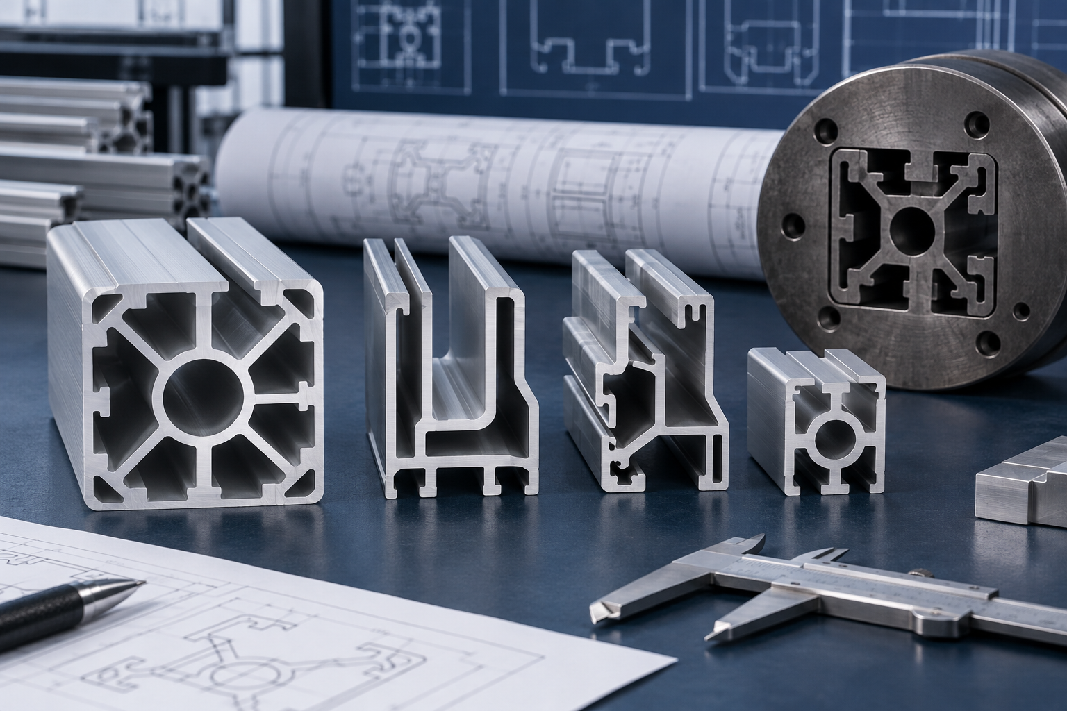
Design the profile around balanced metal flow, stable die support and the variation that the finished assembly can accept. Begin with a compact functional envelope, keep neighboring walls reasonably balanced, use gradual thickness transitions and practical radii, and reduce deep narrow channels or fragile tongue features. Add only the continuous ribs, grooves, ports and hollows that create real product value.
Then separate dimensions controlled by extrusion from features better produced by cutting or CNC machining. Review the cross-section with the intended extruder before releasing tooling because feasible wall thickness, hollow geometry, tolerance and press selection depend on the complete combination of alloy, temper, profile size, complexity, length and order requirements.
A manufacturable profile is not merely one that can exit a die once. It must remain controllable through cooling, stretching, straightening, cut-off, finishing, machining, inspection and assembly. The drawing therefore needs functional datums and acceptance methods, not a blanket demand that every nominal CAD dimension be held tightly.
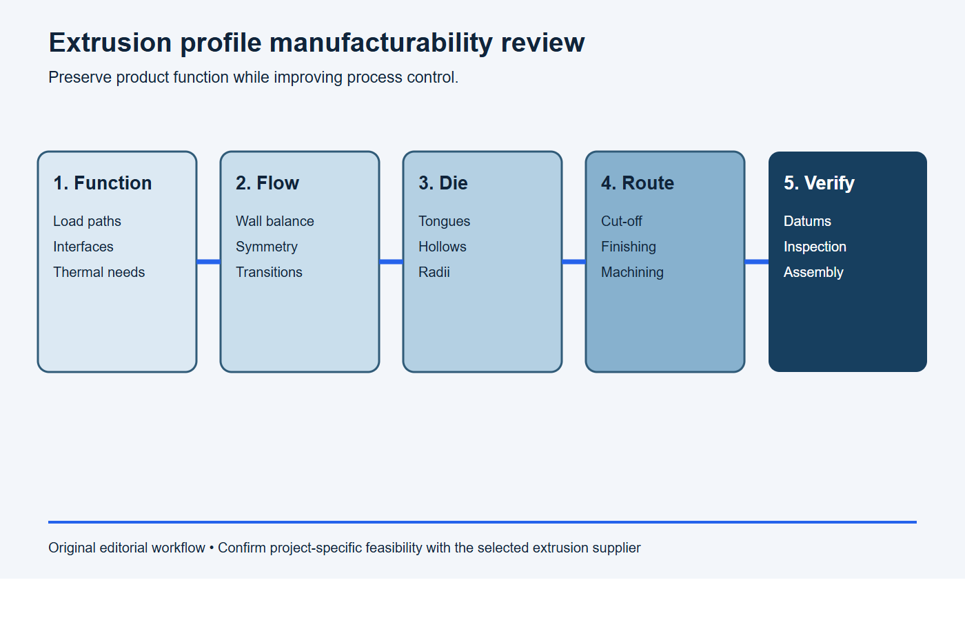
Use this manufacturability review in five passes
- Function: mark the features that carry load, locate parts, transfer heat, seal, fasten or control appearance.
- Cross-section: retain continuous geometry that earns its place and remove local detail better made later.
- Die feasibility: review wall balance, tongues, hollows, radii, alloy and press suitability with the intended extruder.
- Downstream route: check cut-off, straightening, machining, finishing, inspection, assembly and packaging.
- Release: approve one drawing and model with agreed tolerances, datums, sample evidence and change control.
Start with the smallest useful continuous cross-section
List the functions that repeat along the full part length: carrying bending loads, enclosing electronics, guiding a slider, transferring heat, locating a panel, routing a cable or capturing a fastener. These are strong candidates for the extruded cross-section. Features that occur at one station—cross-holes, localized pockets, end faces, connector windows or sealing lands—usually belong in a secondary operation.
Keep the overall envelope no larger than the product needs. The Aluminum Extruders Council uses the circumscribing circle diameter, the smallest circle that encloses the cross-section, as one factor in press selection and economics. Weight per unit length also affects press operation. There is no universal optimum size: ask the selected supplier to assess the actual profile, alloy and required volume.
| Feature need | Good extrusion candidate | Consider a later operation when |
|---|---|---|
| Structural stiffness | Continuous webs, ribs or closed sections along the length | Reinforcement is needed only around a local load or joint |
| Fastening | Continuous screw port, nut channel or locating groove | Hole position must relate precisely to a cut end or local datum |
| Thermal control | Continuous fins and heat-spreading walls | A local cold plate, sealed passage or interface needs separate verification |
| Enclosure | Continuous shell, rail, cover groove or cable channel | Connector windows, gasket faces or access pockets are localized |
Balance wall thickness without forcing every wall to match
Relatively uniform neighboring walls help metal move through the die and cool more consistently. Large thick-to-thin changes can create unequal resistance and thermal behavior, which may show up as surface variation, distortion or difficulty controlling the cross-section. The AEC’s extrusion design tips specifically advise keeping wall thicknesses uniform and using symmetry where possible.
Uniform does not mean identical. A load-carrying base may need to be thicker than a cover wall, and a fin may need a different section for thermal performance. Make transitions gradual, use a radius or taper where function permits, and ask whether the extra mass is carrying load, spreading heat, holding a fastener or providing machining stock. Remove unsupported material only after structural, thermal and assembly requirements are checked.
Avoid publishing a generic minimum wall as a project guarantee. The workable limit changes with alloy, temper, circumscribing circle, wall length, aspect ratio, die support, surface expectation and production rate. Mark the function-driven walls on the drawing and let the extrusion supplier propose adjustments to noncritical regions.
Use symmetry to improve the starting condition
A symmetric section often gives the die designer a more balanced starting point for metal distribution and cooling. If the product cannot be symmetric, distribute mass as evenly as the functional envelope allows. A heavy base with a cluster of thin features on one side deserves early review because the two regions will not behave alike.
Useful changes can include moving a rib, mirroring a groove, opening an unnecessary pocket or dividing a large asymmetric profile into compatible pieces. Do not add material only to make the drawing look symmetric. The goal is balanced behavior while preserving load paths, interfaces and assembly access.
Reduce deep channels and high tongue ratios
A deep narrow slot leaves a slender steel feature in the die. As the slot becomes deeper relative to its opening, that tongue becomes more difficult to support and more exposed to pressure and deflection. The AEC identifies high tongue ratios as a shape constraint and recommends redesigning deep, narrow tongues where possible.
Evaluate these alternatives:
- widen the channel opening while preserving the functional internal space;
- reduce depth or divide one deep channel into shallower functional features;
- add a larger root radius or taper when it does not interfere with the mating part;
- change the mating hardware so the narrowest section is no longer continuous;
- extrude an open profile and add a cover when a fully enclosed route is unnecessary.
Do not copy a tongue-ratio limit without confirming the definition and conditions used by the quoting extruder. Supplier capability, alloy, profile size and tooling concept determine the practical answer for the controlled drawing.
Choose solid, semi-hollow or hollow geometry deliberately
A solid profile has no completely enclosed void. A hollow profile contains one or more enclosed voids. A profile that partially encloses a void may be classified as semi-hollow or solid under the applicable geometric definition; the distinction is not always obvious from a CAD view. The AEC advises designers to let the extruder help establish the classification.
Hollow profiles can provide useful torsional stiffness, enclosure volume and integrated passages, but they change die construction and may introduce longitudinal seam considerations from the metal-flow route. Decide whether the void is required for stiffness, routing, sealing or assembly. If not, an open section, two interlocking extrusions, a cover or a later machining operation may simplify tooling and inspection.
Add radii and smooth transitions at junctions
Sharp internal junctions create abrupt changes in metal flow and local stress. Use practical radii at rib roots, boss transitions and wall intersections. Rounded transitions can also reduce stress concentration in service. External corner requirements should account for the desired appearance, mating envelope and finishing method.
Do not set every corner radius from one rule of thumb. The suitable value depends on adjacent wall thickness, die construction and product function. If a mating component needs a visually sharp outside corner, consider whether a small permissible radius or later machining can satisfy the real interface.
Design ribs, bosses and screw ports for their load paths
A rib should connect the surfaces whose relative motion it is meant to resist. A boss should place material around a fastener or machined feature without creating an isolated heavy region. A screw port needs sufficient geometry for the selected fastener, engagement, edge distance and installation method. Validate these functions with the assembly, not from cross-section appearance alone.
Continuous T-slots, dovetails and snap features can consolidate hardware, but they introduce narrow openings and controlled spaces. Model the mating component at its material limits and include surface-finish buildup. For snap or flexible features, verify assembly force, strain, repeated use and environmental effects with representative samples.
Separate extrusion tolerances from finished-part tolerances
An extrusion drawing can contain metal dimensions, space dimensions, wall thickness, flatness, straightness, twist and length requirements. These describe different behaviors and measurement methods. The Aluminum Association’s extrusion tolerance series explains that twist is rotation along the length, straightness limits longitudinal curvature, and flatness applies across a profile surface. It also distinguishes metal and space dimensions for solid and hollow profiles.
Apply a tight requirement only where it protects a measurable function. A broad mounting face may need control over a defined span, while a local bearing seat may be better machined. A sliding channel depends on the mating envelope and engagement length. A cosmetic surface may need an appearance standard rather than a tighter dimensional tolerance.
| Requirement | Manufacturability question | Possible control route |
|---|---|---|
| Channel clearance | Does the mating part fit across expected metal and space variation? | Functional gauge, agreed profile tolerance or local machining |
| Long mounting rail | What straightness and twist affect assembly over the engagement length? | Defined support and measurement method; straightening if agreed |
| Sealing face | Can the as-extruded surface provide the required contact condition? | Controlled extrusion surface, machining, finishing and leak verification as applicable |
| Cross-hole location | Must the feature locate from a cut end or assembly datum? | CNC machining from functional datums |
Choose datums that survive extrusion variation
Locate the profile in inspection and machining from broad, stable and accessible surfaces. Avoid using a flexible lip, narrow fin, burr-prone cut edge or cosmetic edge as the primary reference unless the product truly locates there. If the finished part needs accurate secondary features, design datum pads or rails that fixtures and gauges can reach without excessive clamping force.
State the drawing standard and define the functional relationship clearly. ASME Y14.5-2018 (R2024) establishes rules for dimensioning, datum references and geometric tolerancing. It does not replace the extrusion-product tolerance standard; use each document only for its intended scope and identify the governing requirements on the drawing.
Plan finishing and secondary machining before freezing the profile
Anodizing, coating, brushing and polishing affect dimensions, appearance, contact areas and handling. Provide finish allowance where fit depends on a treated surface. Mark electrical contact, grounding, masking, threaded and sealing regions. Define cosmetic zones and viewing conditions so appearance requirements are inspectable.
For CNC operations, add stock where a cutter must establish a precise face, hole or pocket across expected extrusion variation. Provide workholding access and chip clearance. Position machined features from the functional datum system rather than chaining them through several uncontrolled profile dimensions. BAOSONG’s guides to aluminum CNC milling, practical CNC tolerances and anodized aluminum support this downstream review.
Review the entire production route with the supplier
Before tooling release, review alloy and temper, profile classification, circumscribing circle, weight per length, wall transitions, tongues, hollows, tolerances, expected length, cut method, straightening, finish, machining and packaging. Ask which dimensions the extruder expects to control directly, which require process development, and which should be machined.
Alloy and temper affect extrudability, properties, finishing and the downstream route. Use the applicable material specification and do not treat 6061, 6063 or another grade as universally interchangeable. BAOSONG’s aluminum temper guide explains T5, T6 and T651 terminology, while project-specific availability and properties still require confirmation.
Define how samples will be approved. Inspection needs a stated support condition, evaluation length, datum setup and calibrated equipment suitable for the requirement. NIST’s measurement and calibration resources illustrate the breadth of dimensional measurements and traceability; the project quality plan must still match measurement uncertainty to the actual acceptance limit.
Common manufacturability mistakes
- Freezing detailed CAD before extrusion review: small changes become harder after mating parts and tooling are committed.
- Using a universal minimum wall: feasibility depends on the entire alloy–geometry–press combination.
- Creating deep narrow channels for local features: move local detail to machining or assembly when continuous extrusion adds no value.
- Applying tight tolerances everywhere: connect each tolerance to fit, sealing, motion, appearance or inspection.
- Ignoring cut-off and finishing: the finished part includes end condition, surface treatment and handling effects.
- Choosing weak datums: flexible or inaccessible surfaces make both machining and verification unstable.
- Approving only a short section: full-length straightness, twist and assembly behavior may require representative-length validation.
Stop conditions: the profile is not ready for tooling
- A wall, rib, channel, hollow or screw port has no stated product function.
- The selected extruder has not reviewed profile classification, tongue support, wall balance or press fit.
- Critical dimensions have no agreed tolerance category, datum or measurement method.
- CNC machining allowance assumes the nominal extrusion surface will always arrive in the same location.
- Finish buildup, rack contact, cosmetic zones or full-length straightness and twist remain unresolved.
Copy-ready manufacturability review request
Please review aluminum extrusion profile [part number/revision] for [application, cut length and quantity]. Mark each geometry or tolerance that raises die, metal-flow, cooling, straightening, cut-off, machining, finishing or inspection risk. For every proposed revision, state the affected function and the verification method that will remain. Confirm profile classification, alloy/temper, proposed tolerance standard, tooling assumptions, sample plan and the characteristics that should be CNC machined. Do not release tooling until all model, drawing and acceptance conflicts are closed.
Aluminum extrusion profile DFM checklist
- Identify the functions that must be continuous along the length.
- Reduce the envelope and remove geometry without a defined function.
- Balance neighboring walls and smooth thick-to-thin transitions.
- Use symmetry or balanced mass where the product permits.
- Review deep channels, tongue features, hollows and enclosed spaces.
- Add radii at wall, rib and boss junctions.
- Separate as-extruded requirements from cut and CNC-machined features.
- Define stable datums and inspection methods.
- Account for finish buildup, cosmetic zones and handling.
- Complete an extruder review before tooling release and approve representative samples against the controlled drawing.
Frequently asked questions
Must an aluminum extrusion have uniform wall thickness?
No. Similar neighboring walls often support more balanced processing, but functional loads, thermal needs and machining stock may justify differences. Use gradual transitions and have the extruder review the complete section.
Are hollow profiles always harder to manufacture?
Hollows require a different tooling and flow strategy, but difficulty depends on void geometry, bridges, wall distribution, alloy, profile size and tolerances. Keep a hollow only when it delivers needed stiffness, enclosure, routing or assembly value.
Which dimensions should be CNC machined after extrusion?
Consider machining for local holes, pockets, end faces, bearing seats, sealing surfaces and tight relationships to a finished datum. The correct choice depends on functional tolerance, available stock, workholding and inspection access.
What should engineers send for a DFM review?
Send the controlled 2D drawing and 3D model, alloy and temper, application, critical characteristics, finish, part length, machining needs, sample and production quantities, inspection documents and mating-interface information.
Request an engineering review
BAOSONG supports custom profiles that combine aluminum extrusion services, secondary machining and surface finishing. Review the information needed for engineering support, then send the drawing, model, material, critical dimensions, finish and production quantity through the contact page for an engineering review and quotation.
Recommended Downloads for Aluminum Extrusion Design
Use these BAOSONG references to set profile geometry, wall thickness, tolerances and downstream CNC features before releasing an extrusion design.
- Custom Aluminum Extrusion Design Guide (PDF)
- Wall Thickness and Tolerance Guide (PDF)
- CNC Machining Guide for Aluminum Extrusions (PDF)
- Aluminum Alloy Comparison Chart (editable Excel)
Need help checking an extrusion profile or manufacturability risk? Contact BAOSONG Precision.
