
Quick answer: what should a drawing for a custom aluminum manufacturer contain?
A production drawing should identify the part and revision, units, alloy, temper, product form, finish, governing standards, functional datums, critical dimensions and tolerances, threads, edge conditions, surface requirements and inspection expectations. It should agree with the supplied 3D model and make the acceptance condition unambiguous.
Use the drawing to communicate design intent rather than to prescribe every cutting move. Dimension the relationships that control fit, sealing, alignment, thermal contact and appearance. Allow the manufacturer to select fixtures, tools and process sequence unless a particular route is a validated requirement.
Before release, review the definition as a connected system: model, drawing, referenced specifications, mating interfaces and bill of materials. Remove conflicting duplicates, identify the source of authority and test whether a manufacturer and inspector can reach the same interpretation without private assumptions.
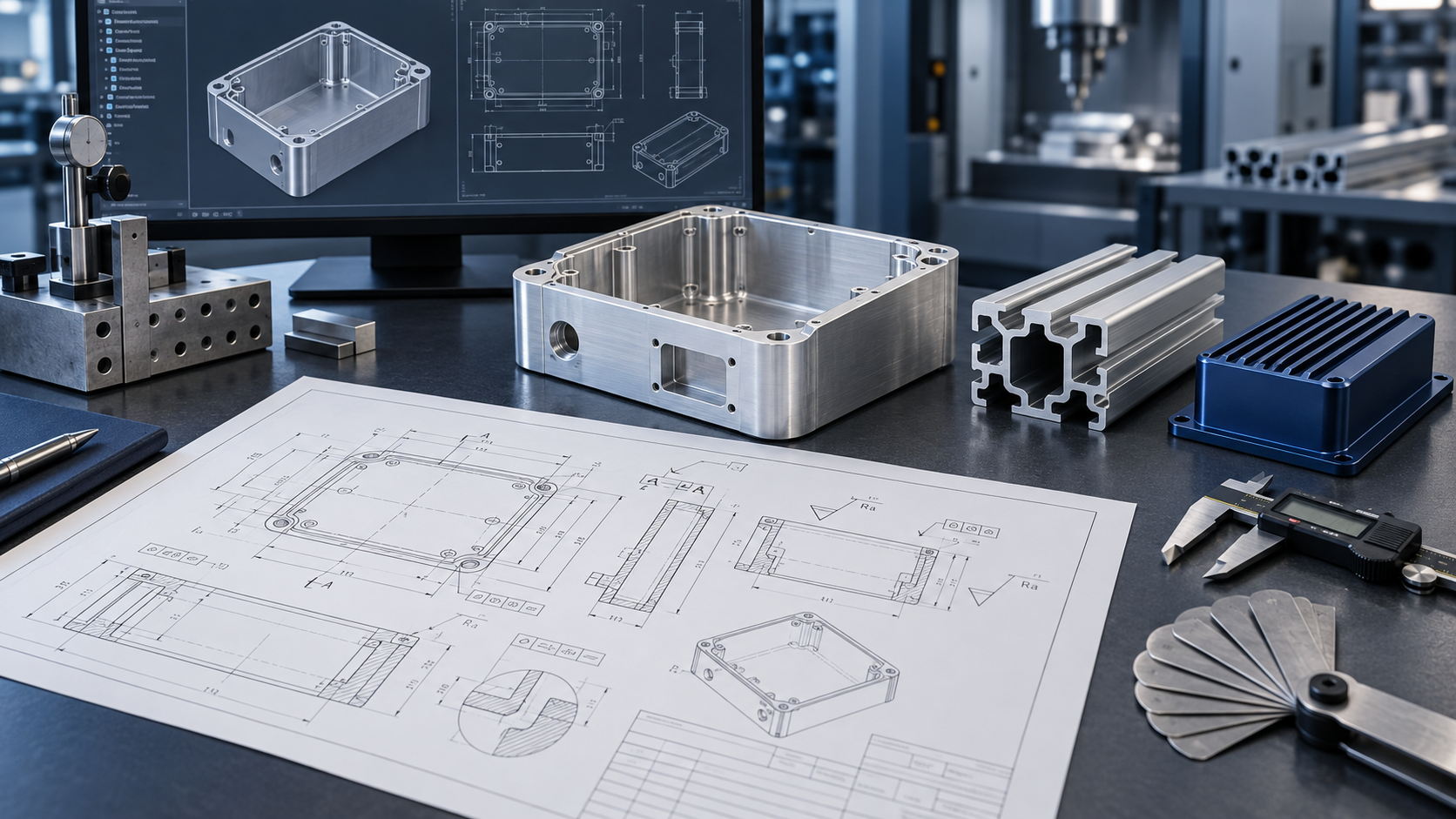
Declare which file controls the product definition
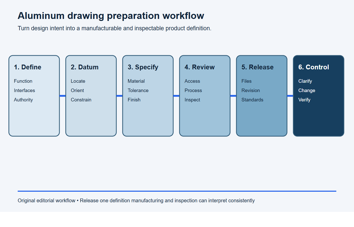
Use this sequence before releasing the package:
- Declare the authority. State whether the 2D drawing, model or model-based definition controls and list every referenced file and revision.
- Define material and process state. Specify alloy, temper, product form, blank condition, heat treatment and final finish.
- Build functional datums. Dimension fits, sealing, alignment, thermal contact and assembly interfaces from references that reproduce use.
- Complete manufacturable details. Define holes, threads, inserts, edges, radii, surface texture, masking and cosmetic zones.
- Prove inspectability. Match each critical requirement to a feasible measurement and run an independent release review.
If both a 3D model and 2D drawing are supplied, state how they work together. The model may define nominal geometry while the drawing controls tolerances, material, finish and notes. If model-based definition is used, identify the relevant standard and ensure semantic annotations survive the exchange format.
Provide a neutral STEP file when practical and the native CAD file when compatible. Check units, scale, coordinate system, suppressed features, multiple bodies and export accuracy. Give every file a part number and revision; avoid filenames such as “final-new-2.”
ASME Y14.100-2017 establishes requirements for preparing and revising engineering drawings and associated lists. The broader ASME Y14 collection includes drawing types, digital product definition, revisions and related documentation. Cite the exact system and edition used by your organization.
Complete the title block and general notes
| Field | What to state | Risk if missing |
|---|---|---|
| Identity | Part number, name, revision and sheet count | Wrong file or incomplete drawing set |
| Units | Millimetres or inches and angle convention | Scale and conversion errors |
| Material | Alloy, temper, product form and standard | Incorrect stock or properties |
| Finish | Process, specification, class, color and masking | Uncontrolled appearance or buildup |
| Tolerances | General scheme, decimal places, angles and governing standard | Ambiguous untoleranced features |
| Approval | Released status, dates and change reference | Manufacture to unapproved data |
Use general notes only for requirements that truly apply across the drawing. Put local requirements next to the affected feature. Do not bury a critical seal-surface flatness or cosmetic restriction in a long boilerplate list.
Specify alloy, temper and product form
“Aluminum” or even “6061” is incomplete. State the full temper and whether the blank is plate, bar, extrusion, sheet, forging or casting. Product form affects tolerances, mechanical properties, residual stress, grain flow and availability.
Reference the material standard and edition required for purchase. State whether mill certificates, heat or lot traceability and country-of-origin documentation are needed. If equivalent material may be proposed, define the approval route instead of writing “or equivalent” without criteria.
BAOSONG’s CNC aluminum alloy guide and 6061 versus 6063 comparison support early selection. The released drawing and purchase order should control the final requirement.
Choose datums from the way the part functions
Datums establish the reference frame for manufacturing and inspection. Select stable features that locate the part in its assembly: a mounting plane, locating bore or side face. Follow the actual constraint sequence rather than choosing the largest convenient surface automatically.
Define primary, secondary and tertiary references that remove the required degrees of freedom. Consider how each datum can be contacted in a fixture and inspection setup. A flexible wall, unfinished casting surface or tiny pad may be a poor datum even when it is visible in CAD.
Use ASME Y14.5-2018 (R2024) when that system governs the drawing. For ISO-based definitions, the ISO GPS standards index includes datum and geometrical-tolerancing standards. Do not mix symbol systems or default rules without an explicit interpretation basis.
Apply GD&T only where relationships matter
Use position to control hole patterns relative to functional datums, profile to control complex surfaces, perpendicularity or parallelism for orientations, flatness for an individual surface and runout where rotation makes it functional. Select tolerances from assembly analysis and verification capability.
A coordinate ± tolerance may allow a square zone while the function needs a cylindrical positional zone. Conversely, an elaborate feature-control frame adds no value when a simple size tolerance fully describes the requirement. Make the drawing readable to manufacturing and inspection teams.
Avoid double dimensioning, closed chains and redundant controls that can conflict. Mark dimensions as basic, reference or inspection-only correctly. Verify material-condition modifiers and datum boundary assumptions through a worst-case assembly analysis.
Do not use tight tolerances as a substitute for design decisions
Apply tight limits to sealing faces, bearing seats, connector positions and other functional features. Use broader tolerances on clearance pockets, nonmating walls and cosmetic edges. Uniform precision across the part increases cycle time, fixturing effort, inspection and rejection risk.
BAOSONG’s aluminum machining tolerance guide explains practical drivers including part size, wall thickness, datum access, temperature and inspection method. Ask the manufacturer to review high-risk features before release.
If a general tolerance standard is used, cite its edition and scope. Do not assume the number of displayed decimal places has the same meaning at every supplier. Explicitly tolerance features whose function cannot accept the general rule.
Define holes, threads and inserts completely
For holes, state diameter, depth or through condition, position, counterbore or countersink, bottom geometry and quantity. Distinguish drilled depth from full-diameter depth. Identify reamed, bored or fitted holes by their functional requirement.
For threads, specify standard, nominal size, pitch, class or fit, handedness, depth and insert if used. Clarify whether thread depth means minimum full thread and whether plating or anodizing applies. Provide lead-in and tool clearance where assembly permits.
For threaded inserts, identify manufacturer or performance requirements, installation side, orientation and pull-out or torque validation if needed. Consider wall thickness and boss geometry early rather than adding inserts after a thin section is frozen.
Call out edges, radii and internal corners
“Break all sharp edges” is ambiguous unless the allowed edge range is defined. State a chamfer, radius or maximum edge break, and identify edges that must remain sharp for sealing or locating. Define burr direction or inaccessible-cross-hole requirements where relevant.
Internal machined corners need tool radius. Provide the largest radius the function permits, especially in deep pockets. Avoid zero-radius CAD geometry unless another process creates it. BAOSONG’s extrusion plus CNC machining guide also shows why machining allowance and selected precision features should be defined before the blank is finalized.
Separate surface roughness from cosmetic finish
Surface roughness is a measured texture requirement; cosmetic appearance also depends on tool path, grain direction, reflectivity, scratches, handling and coating. Apply numerical roughness only to surfaces whose function requires it, such as seals, bearings or thermal contacts.
Specify whether a visible surface is as-machined, brushed, blasted, polished, anodized or coated. Define grain direction, Class A zones, allowed rack marks, approved samples and viewing conditions. Use BAOSONG’s surface-finishing overview and anodizing page.
Clarify the sequence. A dimension measured before anodizing may change after coating; masking can preserve electrical contacts, tight fits and threads. State which requirements apply to the final finished part.
Prepare extrusion drawings differently from machined-part drawings
| Drawing area | Extruded profile | Finished machined part |
|---|---|---|
| Geometry | Controlled cross section and profile envelope | Cut length, holes, pockets and interfaces |
| Tolerances | Wall, profile, twist, straightness and extrusion standard | Datums, position, flatness and local size |
| Material | Alloy, temper, finish and weight per length where needed | Same material identity plus final process state |
| Allowance | Stock for cleanup at critical faces | Final dimensions after machining and finish |
| Inspection | Sample length, support and section measurement | Completed part in defined datum setup |
The Aluminum Extruders Council design tips connect profile geometry with tolerances, fabrication and finishing. BAOSONG’s custom extrusion guide explains what to define before die development.
Show welding, joining and assembly requirements
Identify weld symbols, joint type, length, location, contour, applicable welding standard and inspection. State whether dimensions apply before or after welding. Provide machining allowance and final datums when welded distortion affects critical interfaces.
For fasteners, specify grade, coating, torque, locking method and supplied hardware. For adhesives or sealants, state approved material, surface preparation, bead or bond geometry, cure and acceptance. Include a bill of materials and assembly drawing when multiple parts are delivered together.
Make inspection possible from the drawing
For each critical characteristic, ask whether a suitable instrument can access the feature, establish the datums and achieve adequate uncertainty. Deep bores, hidden channels and flexible surfaces may require dedicated fixtures, gages, sectioning or process validation.
State first-article scope, ballooned drawing expectations, sampling and reporting format in the quality plan. NIST’s publication on uncertainty and dimensional calibrations reinforces why an acceptance decision needs a defined measurement process.
Run a drawing release review
- Confirm part number, revision, units and file authority.
- Verify model and drawing geometry agree.
- Check alloy, temper, product form and material standard.
- Trace datums and tolerances through the mating assembly.
- Review tool access, walls, corners, threads and machining allowance.
- Confirm finish, masking and final inspection condition.
- Check every referenced specification is included or accessible.
- Run manufacturability and inspection reviews before release.
Drawing package checklist
Paste this release statement into the transmittal and attach the indexed product-definition package.
Drawing release: The controlled definition for [part number and revision] is [2D drawing / model-based definition], supported by [model and specification list]. Units, projection, general tolerances and governing standards are [details]. Material is [alloy, temper, product form and standard]; finish and final inspection state are [details].
Supplier response: Review datum access, stock condition, tools, inspection, finish sequence and assembly interfaces. Return a written list of questions, assumptions and proposed deviations before manufacturing. Do not resolve conflicts through shop-floor interpretation; obtain an approved revision or documented concession.
- Controlled native and neutral 3D models.
- Released 2D drawing with part number and revision.
- Units, projection, scale and source-of-authority statement.
- Alloy, temper, product form and material standard.
- Functional datums, GD&T and justified tolerances.
- Complete holes, threads, inserts, edges and radii.
- Surface roughness, finish, masking and cosmetic zones.
- Extrusion blank, machining allowance and process state.
- Welding, joining, hardware and assembly information.
- Inspection method, first article and reporting requirements.
Stop conditions: the drawing is not ready for release
Hold the drawing package if any item below remains unresolved.
- the model, drawing, specifications or bill of materials contain conflicting revisions;
- the source of authority, units, projection or general tolerances are unclear;
- alloy is stated without temper, product form or material standard;
- datums follow convenient edges rather than functional assembly interfaces;
- tight tolerances lack a fit, seal, alignment or measurement reason;
- threads, inserts, edge breaks, internal radii or finishing state are incomplete;
- surface roughness, cosmetic appearance and coating requirements are mixed together;
- an independent reviewer cannot manufacture and inspect the part without private assumptions.
Before issuing the package, ask a person who did not create the model to review it from the manufacturer’s perspective. They should be able to identify the blank, establish the datums, interpret every critical control, plan access and understand the finished acceptance state. Record unresolved questions and close them through a released revision rather than informal markup.
Frequently asked questions
Do I need a 2D drawing if I have a STEP file?
Usually yes for controlled production. The drawing communicates tolerances, datums, material, finish, threads, edge conditions, inspection and revision information that may not exist in a neutral model.
Should every dimension have a tight tolerance?
No. Tighten features that control fit and function. Use suitable general tolerances for noncritical geometry and confirm the manufacturing process can reproduce and inspect the critical relationships.
Should dimensions apply before or after anodizing?
State the required condition explicitly. Fits, threads, seal faces, bonding lands and cosmetic surfaces may need different masking and inspection rules.
Can the manufacturer correct an incomplete drawing?
A capable manufacturer can identify risks and propose clarifications, but the design owner should approve changes and issue a controlled revision before production.
Send BAOSONG a controlled drawing package
After completing the drawing, include it in the broader manufacturing RFQ with quantities, delivery, inspection and commercial scope. Send the controlled files through the contact page for manufacturability and quotation review.
Recommended Downloads for RFQ & Supplier Qualification
Use these BAOSONG templates to prepare complete RFQs, align supplier quality expectations and reduce review cycles before quotation or NPI release.
- Aluminum Manufacturing RFQ Checklist (editable Excel)
- Drawing Review Submission Checklist (editable Excel)
- New Product Introduction Information Sheet (editable Excel)
- Supplier Quality Requirement Template (editable Excel)
Need help preparing an RFQ or supplier document package? Contact BAOSONG Precision.
