
Quick answer: when does aluminum extrusion plus CNC machining save cost?
Aluminum extrusion plus CNC machining can reduce total production cost when most of a part has one constant cross-section and CNC is needed only for local features such as cut ends, datum faces, holes, threads, slots or sealing interfaces. Extrusion places material close to the final shape; machining then creates the features that need tighter control or cannot run continuously along the profile.
The route usually becomes more attractive after the section is stable and repeat demand can absorb the extrusion die, machining fixture, trial and qualification costs. It may not save money for early prototypes, frequently changing designs, fully three-dimensional parts or profiles that still require heavy machining on most faces.
Compare the complete program rather than one piece price: tooling, minimum production quantity, material yield, machining cycle, setups, finish, inspection, inventory and revision risk. The break-even point is project-specific, so a credible supplier should calculate it from the released geometry and demand schedule instead of quoting a universal volume.
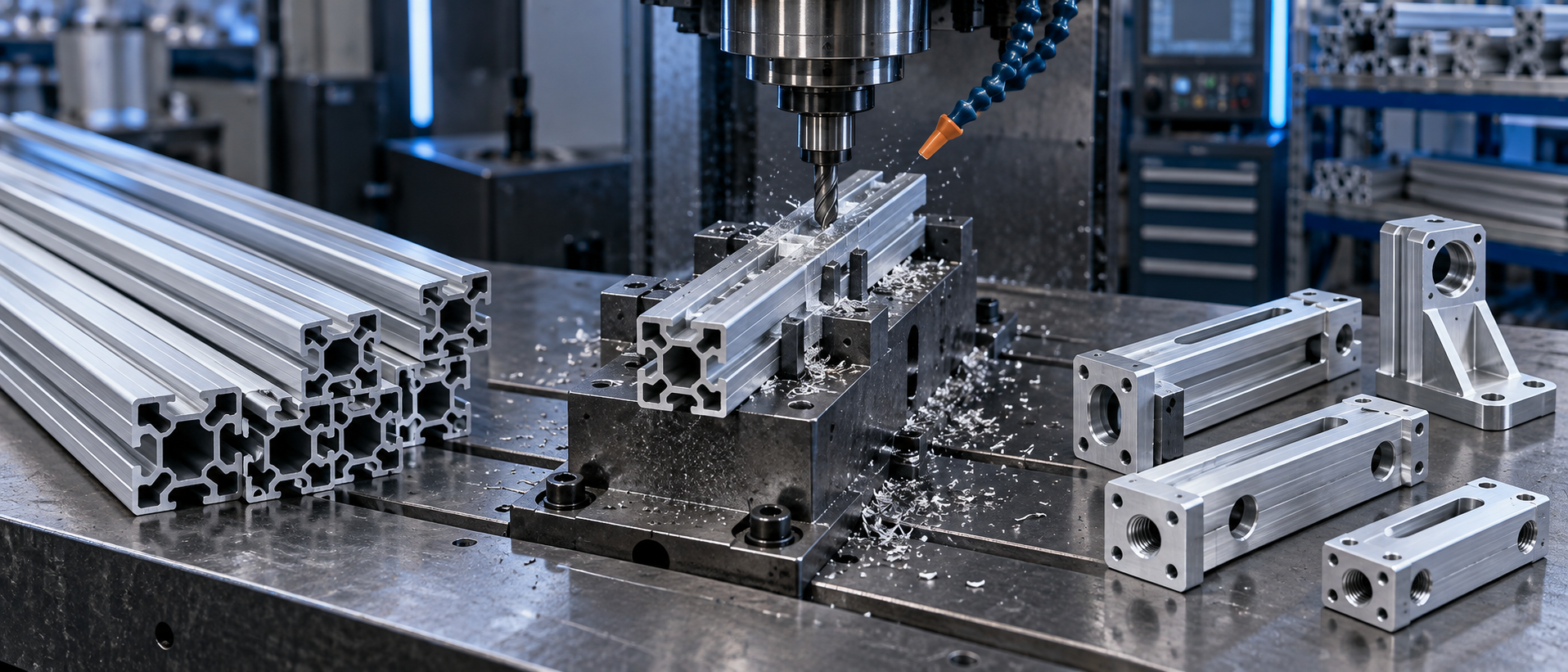
Use this four-step cost test before ordering a die
- Overlay the routes: compare the billet blank and proposed extrusion against the same finished model.
- List every operation: include tooling, trials, cutting, setups, machining, finish, inspection, packaging and inventory.
- Model demand: calculate committed, realistic and downside quantities instead of using one optimistic lifetime volume.
- Validate the assumptions: approve extrusion samples, machining datums, finished tolerances and repeat controls before claiming savings.
How the hybrid process changes the cost structure
Machining from plate or bar pays for material that may later become chips, plus the spindle time, tools and handling needed to remove it. A custom extrusion moves part of that shape creation into a continuous forming operation. The Aluminum Extruders Council design resources describe machining as one of the fabrication methods used to turn an extrusion into a finished component.
The hybrid route does not eliminate CNC cost. It changes what the machine must do. Ideally, the profile supplies walls, ribs, channels, bosses and other repeated longitudinal geometry, while CNC concentrates on functional interfaces. Savings can come from four mechanisms:
- less purchased metal per finished part when the profile follows the useful section;
- less roughing and fewer deep material-removal operations;
- shorter machining cycles when local features remain accessible;
- repeatable loading when the profile includes practical locating and clamping surfaces.
Those gains must exceed the added die, development, extrusion setup, fixture and supply-chain costs. For this reason, extrusion plus CNC is an economic route only after geometry, volume and verification are evaluated together.
Which parts are good candidates?
Strong candidates have a useful cross-section that repeats along a meaningful length. Common examples include equipment rails, linear housings, electronics enclosures, heat-sink bodies, structural members, actuator bodies and mounting beams. A profile may integrate screw bosses, guide channels, cable paths or fin structures before local machining adds interfaces.
The profile should still be practical to extrude. The AEC notes that cross-section size, weight per length, balanced walls, hollows, tongue ratios and symmetry affect extrudability and cost in its key design considerations. A near-net section that is unnecessarily difficult to extrude may move cost from CNC operations into die correction, press constraints or lower yield.
| Part condition | Extrusion plus CNC fit | Reason | What to verify |
|---|---|---|---|
| Constant section with local holes and end features | Strong candidate | Extrusion creates most material distribution; CNC stays localized | Profile tolerance, cut-length datum and feature access |
| Long rail with repeated mounting pattern | Often suitable | Near-net rail may reduce stock and roughing | Fixture support, accumulated pitch and straightness |
| Thin-wall enclosure with machined connector openings | Potentially suitable | The body and internal channels can be continuous | Clamping distortion, cosmetic surfaces and finish sequence |
| Low-volume design with an unstable section | Usually weak initially | Tooling and revision exposure can outweigh unit savings | Prototype learning plan and release gate |
| Complex 3D shape changing along every axis | Usually weak | A constant-section blank does not remove enough CNC work | Billet, casting, fabrication or another near-net route |
Use a break-even model instead of a fixed volume rule
No single quantity makes this route economical for every part. The correct break-even calculation compares the additional non-recurring investment with the verified saving per acceptable finished part.
Illustrative decision equation: break-even quantity = additional hybrid-route investment ÷ expected saving per acceptable part.
The numerator can include the extrusion die, support tooling, CNC fixture, gauges, samples and qualification. The denominator should compare equivalent delivered parts and include material, machining, tools, handling, finishing, inspection, expected yield and logistics. This is a planning equation, not a BAOSONG price or savings claim.
Run at least three demand cases: the committed order, the realistic repeat forecast and a downside case. If the project works only at an optimistic lifetime volume, retaining billet CNC during validation may control revision risk. A custom aluminum extrusion review should define the section and tooling scope before the comparison is finalized.
Design the extrusion around the material that CNC should not remove
A useful near-net profile preserves the repeated functional envelope without forcing every finished feature into the die. Extrude continuous ribs, walls, channels and approximate bosses when they improve material use. Machine transverse holes, interrupted slots, counterbores, threads, sealing faces and tightly controlled datum interfaces where local cutting provides better control.
Do not copy a billet-machined model directly into a die section. Review wall balance, internal voids, deep narrow tongues and circumscribing circle size. Early engineering support should connect the profile section with downstream CNC machining, so integrated features reduce work without creating inaccessible tools or unstable clamping.
Leave realistic machining stock only where a critical surface will be cut. Excess stock recreates the roughing burden the hybrid route is meant to remove. Too little stock can leave an interrupted cleanup cut if normal profile variation reaches the finished surface. The allowance must be agreed from the profile tolerance, datum strategy, straightening condition and machining fixture.
Separate extrusion tolerances from machined-feature tolerances
An extrusion is not a fully machined blank. Twist, straightness, flatness and metal or space dimensions are distinct profile characteristics. The Aluminum Association’s extrusion tolerance video series explains these categories and points users to ANSI H35.2 tolerance tables. The applicable edition and product conditions should be stated in the purchase specification.
CNC machining can control selected local features relative to defined datums, but it does not automatically correct the entire length of a bowed or twisted profile. A short machined pad may meet its local requirement while an unmachined rail surface follows the extrusion condition. Drawings should identify which surfaces remain as-extruded, which are machined and which relationships are function-critical.
Use GD&T to communicate functional relationships when appropriate. ASME Y14.5-2018 (R2024) establishes the symbols, rules and definitions for stating and interpreting GD&T. The project drawing should define the governing standard, datum reference frame and acceptance method; a machine positioning specification is not a finished-part tolerance.
Datum and fixture design decide whether the saving is repeatable
The fixture has to locate a profile that carries normal extrusion variation without forcing it into a false shape. Over-constraining a long or thin-wall section can create a part that measures correctly while clamped and moves after release. Under-supporting it can cause vibration, chatter or local deflection.
Good planning distinguishes a primary locating surface from clamping surfaces and cosmetic faces. Stops should control cut-length orientation, while support should sit close enough to machined features to resist cutting load. For long parts, multiple supports may be necessary, but their contact must match the intended datum scheme.
Fixture loading and tool access also influence cycle time. A section designed with stable seating lands may support faster, more consistent handling than an irregular profile. However, adding metal only for workholding can erase material savings, so fixture and die concepts should be reviewed together.
Count every secondary operation
A low CNC cycle does not guarantee the lowest delivered cost. Cut-to-length work, deburring, washing, conversion coating or anodizing, masking, inspection and packaging can dominate a simple part. Each handoff can add queue time and a new risk of scratches, mixed orientation or dimensional change.
Sequence matters. Machining before anodizing exposes cut features to the coating and may require dimensional allowance or masking. Machining after anodizing preserves critical metal dimensions at selected interfaces but leaves bright cut surfaces and can damage the surrounding finish. The print should state whether dimensions apply before or after treatment. Review options with the surface-finishing and anodizing requirements together.
Inspection scope must follow function. A practical control plan may check the incoming profile condition, cut blank, first machined setup, finished dimensions and surface condition at different stages. Measurement results also need a method appropriate to the tolerance and an understood uncertainty; NIST’s dimensional calibration guidance explains why uncertainty belongs in interpreting dimensional results. Adding inspection after every operation without a risk-based reason increases cost; measuring only at the end can hide the source of variation.
When billet CNC remains the better route
Machining from solid stock often remains preferable during early design learning, for small or uncertain demand, or when the section changes substantially along the part. It avoids committing to a profile die before the product architecture is stable and allows larger geometry changes through revised programs and fixtures.
Billet CNC can also win when the proposed extrusion leaves almost as much machining as the solid route, when a suitable stock shape is already available, or when special material and temper requirements do not align with an economical extrusion program. Our broader comparison of extrusion versus machining from solid billet covers these route-level choices.
A staged plan can use billet-machined parts for functional prototypes and launch validation, then release the extrusion after section-critical changes are closed. This delays tooling commitment without losing the opportunity to reduce recurring cost later.
A practical route-selection workflow
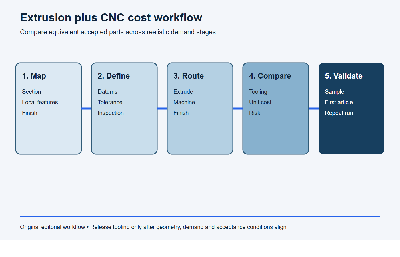
- Map the geometry: mark constant-section material, local precision features and surfaces that can remain as-extruded.
- Define the acceptance state: identify datums, tolerances, finish, inspection records and whether dimensions apply before or after treatment.
- Develop both routes: create a credible billet machining plan and an extrusion-plus-CNC plan, including tooling and revision assumptions.
- Compare equivalent cost: include non-recurring investment, acceptable-part yield, cycle, secondary operations, inventory and logistics.
- Validate in stages: approve the section, sample extrusion, fixture method, first article and repeat production controls before relying on forecast savings.
Stop conditions: the hybrid route is not proven cheaper yet
- The proposed profile does not remove substantial stock or machining operations from the billet route.
- The break-even calculation excludes tooling, minimum runs, yield, fixtures, finishing, inspection, inventory or revision risk.
- The profile datums and machining allowance do not cover expected extrusion variation.
- The forecast saving appears only at an uncommitted lifetime quantity and disappears in the downside case.
- A billet prototype passed, but no production-intent extrusion sample has verified machining, finish and assembly.
Copy-ready hybrid-route comparison request
Please compare billet CNC and aluminum extrusion plus CNC for part [number/revision] at quantities [prototype, batch and annual forecast]. Use the same alloy, temper, finish, tolerances, inspection and packaging. For each route, itemize material input, tooling, fixtures, cycle, setups, secondary operations, expected yield, qualification and inventory. Overlay the proposed extrusion on the finished model, identify every remaining machining operation and calculate break-even under committed, realistic and downside demand. State the validation evidence required before conversion.
Cost comparison checklist for an RFQ
Provide the same requirement package for both candidate routes. A useful RFQ contains:
- 2D drawing and 3D model with revision alignment;
- alloy, temper and acceptable material alternatives;
- annual demand, release quantity, program life and prototype stages;
- critical datums, tolerances, fits, threads and sealing interfaces;
- surfaces permitted to remain as-extruded;
- finish, masking, appearance zones and post-finish dimensional state;
- inspection method, sampling, documentation and traceability needs;
- tool ownership, storage, maintenance and replacement expectations;
- packaging, cut length, delivery cadence and inventory constraints.
Ask the supplier to show the proposed raw section overlaid on the finished part and to identify each machining operation. This makes hidden stock, inaccessible tools and unnecessary finishing cuts easier to challenge before tooling release.
Frequently asked questions
Does extrusion plus CNC always use less aluminum?
It often improves material utilization when the profile closely follows a repeated section, but die trial scrap, cut loss, machining allowance and production yield still count. Compare purchased input with acceptable delivered parts rather than looking only at the finished CAD volume.
Can CNC machining correct all extrusion variation?
No. CNC can create controlled local features from a defined setup, but it cannot automatically remove twist, bow or section variation along every unmachined surface. The datum plan and profile specification must match the functional requirement.
Should the part be fully prototyped before ordering a die?
The functional design and section-critical features should be sufficiently stable before die release. Billet prototypes can verify assembly and interfaces, while an extrusion sample is still needed to validate the real profile, machining fixture and finishing sequence.
How should we compare supplier quotations?
Normalize tooling ownership, quantities, alloy and temper, machined features, finish, inspection, packaging and delivery terms. A lower piece price is not comparable if it excludes fixtures, gauges, qualification or the required acceptance records.
Request a drawing-based process review
BAOSONG supports custom aluminum extrusion and secondary machining projects through drawing review, process planning and production coordination. We can compare a near-net profile route with billet machining once the geometry, demand stages, finish and inspection requirements are available. See our aluminum extrusion services, aluminum CNC machining and quality approach, or send the project package for review.
Recommended Downloads for Aluminum Extrusion Design
Use these BAOSONG references to set profile geometry, wall thickness, tolerances and downstream CNC features before releasing an extrusion design.
- Custom Aluminum Extrusion Design Guide (PDF)
- Wall Thickness and Tolerance Guide (PDF)
- CNC Machining Guide for Aluminum Extrusions (PDF)
- Aluminum Alloy Comparison Chart (editable Excel)
Need help checking an extrusion profile or manufacturability risk? Contact BAOSONG Precision.
