
Quick answer: when is aluminum extrusion better than billet machining?
Aluminum extrusion is usually the stronger starting route when most of a part can be represented by one constant cross-section, demand is repetitive enough to justify a profile die, and CNC machining is needed only for local holes, slots, threads, datum faces or cut ends. Machining from solid billet is usually the better starting route when the section changes substantially along the part, quantities are low, the design is still changing, or tool access makes the geometry straightforward to cut.
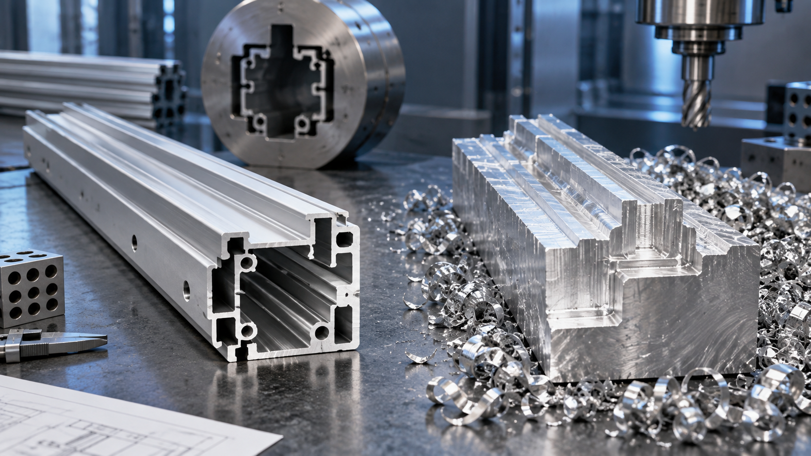
The practical comparison is often extrusion plus secondary CNC versus CNC from plate or bar. Extrusion creates the long-form material distribution. CNC then establishes the interfaces that control fit, sealing, alignment and assembly. This hybrid route can reduce the amount of metal removed and the time spent creating repeated channels, ribs, fins or cavities.
Do not select aluminum extrusion vs billet machining from part quantity alone. Evaluate cross-section stability, alloy and temper, profile feasibility, machining allowance, fixed tooling, material recovery, finished-part cycle time, inspection and the cost of a future design change.
Seven-step extrusion versus billet decision process
| Step | Decision | Required evidence |
|---|---|---|
| 1 | Measure how much geometry repeats along one axis | Section overlay and list of local features |
| 2 | Test profile feasibility and economic value | Extruder feedback, die concept and comparable cost scope |
| 3 | Assign every tolerance to extrusion or CNC | Feature-to-process and datum map |
| 4 | Set machining allowance and workholding | Stock envelope, cleanup allowance and fixture concept |
| 5 | Check whether billet remains the lower-risk route | Design maturity, quantity and schedule assessment |
| 6 | Verify alloy, temper and finish for both routes | Complete material and appearance requirements |
| 7 | Model crossover and validate production | Separated fixed/variable costs and first-article plan |
Step 1: test the repeated cross-section
An extrusion die creates a continuous profile. Every feature formed by the die continues along the extrusion direction unless it is later cut away or modified. This makes extrusion well suited to rails, channels, heat-sink bodies, equipment frames, linear housings, edge members, manifolds and other parts whose functional section repeats.
Ask a simple CAD question: if you take cross-sections at several positions along the component, how much of the useful geometry stays the same? If the walls, cavities, screw bosses, fins and locating grooves repeat, a custom profile may replace a large machined stock envelope. If the geometry changes on several axes, includes closed local cavities, or depends on sculpted surfaces, billet CNC may remain more direct.
The Aluminum Extruders Council’s design guidance identifies circumscribing-circle size, profile weight, wall balance, tongue ratios, hollows and symmetry as feasibility considerations. A section that looks ideal in CAD can still require changes for die strength, metal flow, quenching and handling. Use a custom aluminum extrusion review before freezing wall thicknesses and internal details.
Step 2: confirm feasibility and economic value
Machining from solid stock pays for the starting material, cutting time, tool wear, chip handling and the risk created by long toolpaths. Recovered aluminum chips still have value, but recovery does not restore the machine capacity, labor, coolant management or lead time consumed in making them.
Extrusion can place metal near the load path and form repeated functional details before the part reaches a machining center. The benefit grows when the same section is used across many parts or lengths. One profile may support a product family while saw length, holes and end features create the variants.
The saving is not automatic. A custom die, trial runs, profile correction, minimum production requirements, straightening, aging, cutting, fixtures and inspection add fixed and recurring costs. The AEC’s custom-extrusion white paper specifically warns that complex fabrication, CNC machining and check fixtures can become significant. Its historic prices and order examples are context, not a current quotation.
Request a finished-part comparison from aluminum extrusion production and CNC machining. Include the same alloy requirements, finish, inspection, packaging and accepted-part quantity in both routes.
Side-by-side decision matrix
This matrix is a screening tool. It does not declare a universal break-even quantity or tolerance.
| Decision factor | Extrusion plus secondary CNC | CNC from solid billet | Evidence to request |
|---|---|---|---|
| Base geometry | Repeated walls, channels, ribs, fins, grooves or hollow sections | Local three-dimensional features and changing cross-sections | Section overlay and proposed stock envelope |
| Design maturity | Section is stable enough to release a die | Geometry or interfaces may still change | Revision plan and tooling-change terms |
| Material removal | Near-net section leaves local machining allowance | All removed volume begins as purchased stock | Input weight, finished weight and chip assumptions |
| Precision | Profile follows extrusion tolerances; CNC controls selected features | CNC and workholding control the machined feature network | Feature-to-process map and inspection plan |
| Length variants | One section can be cut and machined into multiple lengths | Stock and toolpaths may change with each variant | Family drawing and annual mix |
| Initial commitment | Profile die, trials and possible dedicated fixtures | Programming, setup and workholding | Separated fixed and recurring quotations |
| Supply planning | Extrusion run size, inventory lengths and remnant strategy matter | Stock availability and size drive purchasing flexibility | Batch plan, stock policy and lead-time basis |
Step 3: assign each tolerance to extrusion or CNC
A profile can leave the press with controlled section dimensions, but it also has process characteristics such as straightness, twist, flatness, contour and metal-versus-space dimensions. The Aluminum Association’s extrusion tolerance guidance explains that these characteristics use different tables and measurement concepts in ANSI H35.2 and Aluminum Standards and Data.
That distinction matters. A general cross-section dimension and the position of a bearing bore relative to a machined mounting face do different jobs. Do not place one tight tolerance across the entire profile when only a local interface requires it. Define which surfaces can remain as extruded, which need machining allowance and which operation establishes each datum.
Secondary CNC machining of aluminum extrusions commonly adds:
- cut length and end squareness that are tied to the final assembly;
- holes, counterbores, threads, slots, windows and connector openings;
- datum pads, gasket lands, bearing seats and mounting faces;
- local pockets that interrupt an otherwise continuous section;
- features that must relate to one another through a defined datum system.
For North American drawings, ASME Y14.5-2018 (R2024) establishes the language for stating and interpreting GD&T. The applicable drawing standard must be named by the customer; it is not created by choosing extrusion or CNC.
Step 4: design machining allowance and workholding
An extrusion-plus-CNC design needs enough stock at machined interfaces to accommodate profile variation, fixturing and cleanup. Excess allowance recreates the material-removal problem the profile was meant to solve, while insufficient allowance risks leaving uncleaned surfaces or losing a critical relationship.
Review where the part will be clamped and how long or thin walls respond to cutting forces. The fixture should locate from stable features without distorting the section into compliance during inspection. When released, a thin profile can move if residual stress, asymmetric material removal or clamp load has been poorly managed.
Deep pockets, tall walls and restricted tool access remain machining concerns even when the blank is extruded. Protolabs’ machinability design guide explains how long tool reach and thin walls can contribute to deflection and poor surface results. Its service-specific limits are not universal; the general design lesson is to examine access, rigidity and workholding for the actual component.
Step 5: confirm whether billet remains the better route
Extrusion is a poor fit when the proposed profile solves little of the final geometry. Continue with billet or plate machining when one or more of these conditions controls the program:
- Very low demand: the required parts do not justify a custom profile run, and no suitable standard extrusion exists.
- Frequent section changes: the design is in validation and a wall, channel or boss may move across the full section.
- True three-dimensional geometry: surfaces, pockets and interfaces change along several axes, leaving little useful continuous section.
- Material availability: the required alloy, temper, stock form or certification is readily available as plate or bar but not as the intended profile.
- Independent feature access: the complete part is straightforward to machine with stable workholding and modest material removal.
- Schedule priority: an available stock route can produce validation parts before a production profile is justified.
Billet machining can also be used as a deliberate bridge. Produce early verification parts, stabilize the interfaces and then redesign the repeated body for extrusion. Document any difference in alloy, temper, grain flow, surface condition and residual stress so the machined prototype is not treated as proof of the production profile.
Step 6: select material, temper and finish for both routes
A wrought alloy name alone does not guarantee identical behavior across plate, bar and extrusion. Product form, temper, thickness and governing material specification affect the property basis. The machining route also changes how much of the original material and surface condition remain in the part.
For many general-purpose profiles, 6xxx-series alloys are common candidates because they can combine extrudability, heat treatment, corrosion resistance, finishing and useful structural properties. The correct grade and temper still depend on loading, section complexity, finish, joining and the applicable specification. Our 6061 versus 6063 guide explains why a familiar grade should not be selected without checking the application and temper.
Define the acceptable substitution policy. If a prototype is machined from 6061-T651 plate and production is planned as a different extruded alloy and temper, validate the production material. Do not transfer prototype strength, fatigue, forming, anodizing or distortion observations without confirming comparable conditions.
Surface finish and cosmetic requirements can change the answer
An extruded surface, a machined surface and an anodized surface have different visual signatures. A long visible housing may benefit from a controlled extrusion surface with local machining hidden at interfaces. A fully machined premium appearance may justify billet cutting when the toolpath itself is part of the visual design.
Mark appearance-critical faces on the drawing and agree on directionality, handling marks, exposed cut ends and the approval sample. Determine whether the finish is applied before or after final machining. Machining after anodizing can expose bare aluminum at a datum or conductive contact; machining before anodizing means the coating can affect final fits and edges.
Use a documented aluminum surface-finishing review to connect substrate, preparation, masking and acceptance. A finish name alone does not establish appearance or finished dimensions.
Step 7: calculate the crossover with comparable quotations
There is no reliable statement such as “extrusion always wins above a fixed number of parts.” A small simple profile and a large hollow profile do not carry the same die, run, machining or inventory costs. A billet component with little material removal may remain competitive at quantities where a heavily pocketed part does not.
Build two models for the same accepted component:
Billet route total = billet programming and fixture cost + quantity × billet finished-part cost.
Extrusion route total = die, trial and fixture cost + quantity × extrusion-based finished-part cost + inventory and revision exposure.
If the extrusion route has higher fixed cost but lower variable cost, a simple modeled crossover is:
Crossover quantity = (extrusion fixed cost − billet fixed cost) ÷ (billet variable cost − extrusion variable cost).
Use only comparable supplier quotations. Variable cost should include the profile or stock, cutting, every machining setup, finishing, inspection, scrap assumptions and delivery. Then test lower demand, a section revision, rejected parts, unused extrusion inventory and additional tool correction. The formula is a planning aid; technical feasibility must be established first.
Three practical selection examples
These are hypothetical examples, not BAOSONG customer cases.
Long electronics enclosure with connector openings
Requirement: continuous walls, internal card guides and several product lengths, with local connector cutouts and end interfaces. Candidate: extrusion plus cutting and CNC. Limiting condition: profile feasibility, straightness, visible surface acceptance and fixture access. Verification: profile dimensional report, machined-feature inspection, finish sample and assembled enclosure test.
Compact optical mount still changing every build
Requirement: intersecting bores and pockets on several faces while the optical layout is evolving. Candidate: billet CNC during development. Limiting condition: tool access, datum transfer and residual stress. Verification: drawing-based dimensional inspection and functional alignment. Revisit extrusion only if a stable repeated body emerges.
Machine rail with repeated channel and local mounting pattern
Requirement: a long stiff section used in several lengths, with accurately located mounting holes and pads. Candidate: extrusion for the rail body and CNC for the mounting network. Limiting condition: section symmetry, straightness, machining allowance and support during cutting. Verification: free-state straightness, datum-related hole inspection and assembly trial.
Production route release checklist
| Gate | Check | Pass evidence |
|---|---|---|
| Profile | Section, hollows, tongues, wall balance, alloy and temper are accepted by the extruder. | Released profile drawing and die quotation |
| Feature map | Every dimension and surface is assigned to as-extruded, cut, CNC or finishing control. | Reviewed process and datum map |
| Cost | Both routes use the same quantity, revision, finish, inspection, scrap and delivery boundary. | Comparable fixed and recurring quotation model |
| First article | Profile characteristics, machined features, free-state geometry and finish are inspected. | Approved first-article report and limit sample |
| Function | Representative parts pass fit, sealing, load, thermal and assembly tests as applicable. | Approved validation result |
| Change control | Die correction, alloy/temper, stock source and section revisions require documented review. | Revision and revalidation workflow |
Stop conditions: do not release an extrusion die yet
- The useful cross-section changes substantially along the part.
- The section is still changing during each prototype build.
- No extruder has reviewed hollow, tongue, wall balance, circumscribing size or die feasibility.
- The drawing applies CNC-level tolerances to the entire profile without a feature-to-process map.
- Machining allowance, cleanup surfaces, clamping and free-state inspection are undefined.
- The production alloy or temper differs from the billet prototype with no correlation plan.
- The crossover model omits tooling correction, minimum run, inventory, finish, inspection, scrap or revision exposure.
Copy-ready route-comparison RFQ checklist
- matching-revision 2D drawing and 3D model;
- part function, load path, mating components and environmental conditions;
- alloy, temper, product-form standard and allowed substitutions;
- critical datums, fits, sealing faces, appearance surfaces and inspection records;
- prototype, launch and repeat quantities by part length or variant;
- expected design-freeze point and features likely to change;
- surface treatment, masking, packaging and traceability requirements;
- a request to separate die, trial, fixture, recurring part and revision costs.
BAOSONG’s engineering support and quality overview show the type of manufacturing and inspection inputs to discuss. Send the drawings and demand stages for a project-specific review of billet CNC, custom extrusion or an extrusion-plus-machining route.
Frequently asked questions
Is extrusion always cheaper than machining from billet?
No. Extrusion can reduce repeated material removal, but it adds profile tooling, run-size, correction, inventory and change exposure. Compare finished-part quotations at realistic quantities after both routes pass technical review.
Can an extrusion hold every finished-part tolerance?
Usually that is the wrong question. Profile dimensions, straightness, twist and flatness belong to the extrusion stage, while selected bores, faces and patterns may be established by CNC. Map each requirement to its controlling operation and measurement condition.
Should prototypes be machined from billet before ordering an extrusion die?
Often yes when interfaces are still changing. The prototype can validate fit and geometry, but differences in stock form, temper and production process must be considered before treating it as evidence for the extruded part.
Can one extrusion serve several finished components?
Yes, if the components share a practical base section. Cut length and secondary machining can create variants. Check whether the common section causes unnecessary material, machining or compromise in any member of the family.
How do I decide which features should be extruded?
Extrude features that repeat along the length and can be formed reliably without creating an impractical die or section. Machine local, interrupted and datum-critical features when that route provides better control. Review the profile and finished drawing together.
Recommended Downloads for Aluminum Extrusion Design
Use these BAOSONG references to set profile geometry, wall thickness, tolerances and downstream CNC features before releasing an extrusion design.
- Custom Aluminum Extrusion Design Guide (PDF)
- Wall Thickness and Tolerance Guide (PDF)
- CNC Machining Guide for Aluminum Extrusions (PDF)
- Aluminum Alloy Comparison Chart (editable Excel)
Need help checking an extrusion profile or manufacturability risk? Contact BAOSONG Precision.
