
Quick answer: how can you reduce CNC machining time without losing function?
Remove time that does not protect the product: unnecessary material removal, avoidable tool changes, redundant setups, difficult tool access, nonfunctional tight tolerances and duplicated inspection. Keep the features that locate, seal, carry load, transfer heat, guide motion or satisfy a controlled appearance requirement.
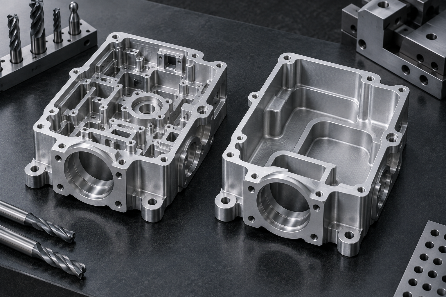
The fastest design is not always the part with the fewest features. A datum pad can shorten setup and inspection. A local corner relief can let a larger cutter reach a deep pocket. Leaving material in a noncritical cavity can reduce roughing while increasing stiffness. The result should be a shorter, more stable manufacturing route rather than a weakened product.
Evaluate time across programming, fixture preparation, cutting, tool changes, repositioning, deburring, finishing and inspection. The exact opportunity depends on alloy, temper, stock form, geometry, quantity and acceptance plan; this article does not state universal BAOSONG cycle times.
Run this review before asking for a lower cycle time
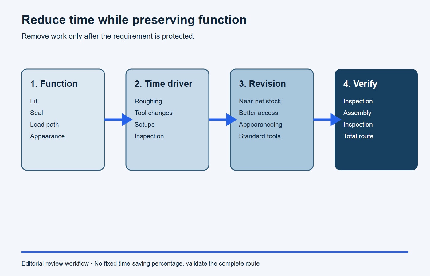
- Mark the functions: identify every sealing face, locating feature, load path, thermal interface, motion feature and controlled appearance zone.
- Map the operations: ask the supplier which stock removal, tool, setup, finish or inspection step consumes the most elapsed time.
- Change one driver: revise geometry, stock form, tolerance, finish or inspection only where the marked function remains protected.
- Verify before release: compare the revised requirement, predicted process route and acceptance method; approve the change through drawing revision control.
Separate time that creates function from time that does not
| Time driver | Why it consumes time | Possible response | Function to retain |
|---|---|---|---|
| Material removal | Roughing, chip evacuation and stress release. | Use near-net stock or leave noncritical material. | Mass, stiffness, thermal path and clearance. |
| Small cutters | Lower rigidity, reduced engagement and extra rest machining. | Increase radii and minimum feature size. | Mating clearance and local geometry. |
| Setups | Handling, locating, probing and datum transfer. | Group accessible features and create stable datums. | Relationships among critical features. |
| Finishing passes | Additional toolpaths and inspection. | Apply texture and tolerance only where needed. | Fit, seal, motion and appearance zones. |
| Inspection | Fixtures, probe access, reporting and review. | Use risk-based characteristics and sampling. | Contractual evidence and product assurance. |
Choose a starting form that removes less material
A billet route offers flexibility, but it can spend most of the cycle converting purchased material into chips. Plate, bar, extrusion, forging or casting may move the blank closer to final geometry. The right choice depends on tooling, minimum order, design stability, material properties, machining allowance and quantity.
For a constant cross-section, compare extrusion plus local machining with full billet removal. For rotational geometry, bar and turning may be more direct than milling. Use the extrusion-versus-billet guide and CNC milling versus turning to select the route before optimizing cutter paths.
Remove pockets that do not earn their cycle time
Weight-reduction pockets can require substantial roughing, corner cleanup and deburring. If a cavity does not provide assembly clearance, fluid volume, thermal behavior or meaningful mass reduction, leaving material may shorten machining and make the part more stable.
Protolabs’ machined-part design guidance also advises reconsidering features that exist only to create unnecessary cutting. Its examples and service limits are supplier-specific; the transferable question is whether each removal operation protects a stated function.
Increase internal radii so a larger tool can work
Small vertical corner radii force small end mills. In deep pockets, the same cutter may need a long reach, reducing rigidity and the amount of material it can remove efficiently. A larger radius can allow a larger tool, reduce rest machining and smooth cutter engagement around corners.
If a square component must fit, add local dog-bone relief or round the mating component instead of sharpening the whole corner. Protolabs’ DFM toolkit connects shared slot and pocket tooling with lower cycle time. Apply that principle to the actual cutter set rather than copying a supplier’s fixed dimensions.
Open deep features and shorten tool reach
Deep narrow pockets add roughing levels, chip recutting and long-reach finishing. Open a side, reduce depth, enlarge the corner radius, machine from another direction or split the component when the assembly permits. Avoid placing a small hole at the bottom of a cavity if it can be approached from an external face.
Keep holder clearance visible in the design review. A tool tip may reach the model while the holder or spindle collides with a wall. The published guide on aluminum CNC milling provides the right service context for discussing tool access and fixture strategy.
Toolpath strategy can reduce load variation after geometry is approved. Seco’s optimized-roughing guidance discusses challenging corners and tall walls as relevant cases. Cutting data, engagement and tool choice still have to be validated for the actual machine, holder, alloy and setup; a CAM strategy cannot correct inaccessible geometry.
Group features to reduce setups
Each setup adds handling, clamping, probing, offsets and the risk of datum-transfer error. Group related holes, faces and pockets so they can be reached from compatible directions. Align critical features to a datum structure the fixture and inspection system can reproduce.
Multi-axis machining may reach several faces in one clamping, but programming and machine cost also matter. Compare total elapsed work for a simple three-axis route, indexed 3+2 machining and simultaneous motion. See 3-axis versus 4-axis versus 5-axis CNC machining and aluminum multi-axis machining.
Reduce avoidable tool changes
Many nearly identical hole sizes, unique radii, decorative chamfers and special thread forms expand the tool list. Standardize noncritical features where the assembly permits. Reuse drill, end-mill and thread sizes without forcing a critical fit into an unsuitable standard.
Raised text, intricate engraving and broad 3D-sculpted surfaces can add small-tool tracing time. Use laser marking, labels or a simpler recessed mark when the requirement allows. Preserve permanent identification and regulatory marking where required.
Design thin walls for stable passes
Thin walls can deflect under cutting and clamping forces. Repeated light passes do not automatically solve movement if the wall remains unsupported. Increase thickness, shorten free height, add ribs or retain temporary support where function allows.
Consider wall stiffness together with material removal sequence and released-state inspection. Stress-relieved plate can reduce one source of movement but cannot make weak geometry rigid. Review T5, T6 and T651 temper meanings before assuming the temper alone will shorten processing.
Use functional tolerances instead of blanket precision
Tightening every dimension can add finishing passes, offsets, process checks and detailed inspection. Identify the bore that locates, the face that seals and the pattern that assembles. Give these features suitable size and geometric controls, then apply an appropriate general tolerance to remaining geometry.
ASME describes Y14.5-2018 (R2024) as establishing symbols, rules and definitions for dimensioning and tolerancing. Use the governing standard and edition required by the project. The guide to practical aluminum CNC tolerances explains how feature-level requirements connect production and verification.
Limit surface texture and cosmetic control to defined zones
Fine texture can require smaller stepovers, slower finishing and separate tools. Cosmetic control can add handling protection, blending and inspection. Define visible zones, sealing faces, sliding interfaces and hidden clearance surfaces separately.
Avoid broad “polish all surfaces” or “no tool marks” notes. Use measurable texture where function requires it and approved appearance criteria where visual consistency matters. This keeps finishing work focused on customer-visible or functional value.
Plan anodizing and masking before machining release
Late finishing decisions can create rework. State whether critical dimensions apply before or after anodizing, which threads and electrical contacts are masked, and where rack marks are acceptable. Coordinate the design with surface finishing and anodized aluminum requirements.
Choose one coherent finish route where possible. Multiple appearances, manual polishing and post-finish remachining add transfers and waiting even when spindle time is unchanged.
Match inspection time to risk
Inspection can become the longest operation on a simple part. Define critical characteristics, first-article scope, in-process checks, lot sampling and final reports. Remove duplicate checks only after the quality plan confirms that product and contractual risks remain controlled.
NIST’s publication on uncertainty and dimensional calibrations explains why measured values are estimates with associated uncertainty. A requirement that is difficult to measure can consume time through special fixtures, repeated alignments and result review. Connect the drawing to the quality and inspection plan.
Optimize the sequence for production quantity
Prototype work benefits from flexible fixtures and stock. Repeat production may justify soft jaws, modular nests, probing routines, tool-life control and near-net material. Automation is valuable only when the design and revision are stable enough to reuse the preparation.
Include prototype quantity, annual demand, batch size and expected revisions in the RFQ. A route optimized for one development part may be slow for hundreds; a dedicated production route may be uneconomic before the design is frozen.
Distinguish cutting time from total production lead time
Shortening the toolpath does not help if the drawing waits for clarification, material arrives without the required certificate or finished parts wait for an undefined inspection report. Track programming, fixture preparation, first-article approval, outside finishing, report review and packaging alongside spindle time.
Resolve model-versus-drawing conflicts before CAM work. Approve material substitutions through one controlled route. Confirm finish and masking before parts enter machining, and define who can approve a deviation. These steps may not change the seconds in a cutting cycle, but they prevent queues, restarts and repeated setups that extend the actual delivery.
For repeat work, keep the released program, fixture definition, tool list, inspection plan and approved finish references under revision control. Reuse is valuable only when the customer’s latest model and drawing still match the validated process.
Use a function-preserving time review
The workflow below starts with the product function, identifies the time-consuming operation, proposes a change and verifies the same requirement before release.
| Function | Time driver | Possible revision | Verification retained |
|---|---|---|---|
| Locate a square module | Small end mill cleans four sharp pocket corners. | Add local corner relief or round the module corners. | Clearance and connector alignment. |
| Reduce housing mass | Large deep cavity requires extensive roughing. | Keep material outside functional clearance or use near-net stock. | Mass, stiffness and thermal performance. |
| Align two bearings | Bores machined and inspected through separate arbitrary datums. | Use one functional datum scheme and compatible setup. | Bore size, axis relation and shoulder location. |
| Provide premium appearance | All faces receive cosmetic finishing and manual handling. | Define visible zones and protected rack/clamp areas. | Approved visible appearance and corrosion requirement. |
Stop conditions: do not approve the time-saving change yet
- The proposal removes or changes a feature, but nobody has confirmed its assembly, sealing, structural or thermal purpose.
- The quoted saving covers spindle time only while adding an extra setup, outsourced finish, special gauge or manual rework.
- The revised stock form changes alloy, temper, grain direction, material certification or minimum-order conditions without approval.
- A tolerance or datum has been relaxed without checking the mating part and the intended inspection method.
- The supplier gives a percentage saving without identifying the changed operation, assumptions, quantity and validation evidence.
Copy-ready cycle-time DFM request
Paste the following into the RFQ or engineering review request, then replace the brackets:
Please review part [number/revision] for cycle-time reduction at [prototype/batch/annual quantity]. Preserve these functions: [fits, seals, loads, thermal paths, motion and cosmetic zones]. Identify the three largest elapsed-time drivers and state the operation, setup, tool, finishing or inspection step involved. For each proposed change, show the drawing or model revision required, the expected effect on total route time, the function retained and the verification method. Quote the current and revised routes separately. Do not substitute material, temper, finish or inspection scope without written approval.
What to send for a cycle-time DFM review
- Matching 3D model and 2D drawing revisions.
- Functions of critical fits, seals, load paths and thermal interfaces.
- Alloy, temper, stock form and approved substitutions.
- Prototype, batch and repeat quantities.
- Critical datums, tolerances, texture and finished-state requirements.
- Cosmetic zones, masking and identification requirements.
- Inspection scope, sampling and traceability.
- Features that may be revised and requirements that cannot change.
Use BAOSONG’s engineering-support resources or send the drawing and production requirements for a manufacturability review. A useful proposal should name the operation removed or simplified and show how the product requirement remains protected.
Frequently asked questions
Does reducing machining time always reduce part cost?
Often, but not automatically. Material, tooling, fixtures, finishing, inspection, scrap risk and capital usage also matter. Compare the complete route.
Should tolerances be loosened first?
No. Start with function. Loosen or reallocate only requirements that do not protect fit, sealing, load, motion or another approved need.
Can five-axis machining always shorten cycle time?
No. It can reduce setups and improve access for suitable parts, but programming, tool motion, machine availability and inspection must be included.
When should time optimization happen?
During DFM before release, then again when quantity becomes stable. Recheck after material, finish, tolerance or design revisions.
Recommended Downloads for CNC Machining Design
Use these BAOSONG references to improve tool access, feature geometry, practical tolerances and CNC process planning before release.
- Aluminum CNC Machining Design Guide (PDF)
- CNC Milling Guide: Pockets, Walls, Corners & Tool Access (PDF)
- CNC Turning Guide: Diameters, Threads & Concentric Features (PDF)
- CNC Machining Tolerance Guide (reference sheet)
- Aluminum Part Design Checklist (editable Excel)
Need help reviewing a machined part or feature stack? Contact BAOSONG Precision.
