
Quick answer: should you choose CNC milling or CNC turning?
Choose CNC turning when the component is mainly rotational and its critical diameters, shoulders, tapers, grooves, bores or threads share a centerline. Choose CNC milling when the component is mainly prismatic and needs flat faces, pockets, slots, contours or hole patterns on one or more planes.
For a round body with flats, cross-holes, keyways or off-axis ports, the practical answer may be turning followed by milling, a turning center with live tooling, or a mill-turn process. Select the route that creates the critical feature relationships in the fewest stable setups, rather than judging only from the part’s overall appearance.
CNC milling vs CNC turning is therefore a geometry, datum and production-planning decision. Review stock form, workholding, tool access, feature relationships, quantity, automation, inspection and finishing before comparing finished-part quotations.
Seven-step milling versus turning decision process
| Step | Decision | Required output |
|---|---|---|
| 1 | Classify rotational, planar, off-axis and freeform features | Feature map and primary-process candidate |
| 2 | Identify critical axes, datums and relationships | Features that should remain in one clamping |
| 3 | Compare separate machines, live tooling and mill-turn | Proposed sequence and transfer strategy |
| 4 | Prove workholding without distortion or damage | Grip, support and released-state plan |
| 5 | Check tool, chip, deburring and inspection access | Manufacturable feature review |
| 6 | Model quantity, automation, material and finish | Comparable accepted-part quotations |
| 7 | Validate the route and control changes | First-article and production control plan |
Step 1: classify geometry by what rotates
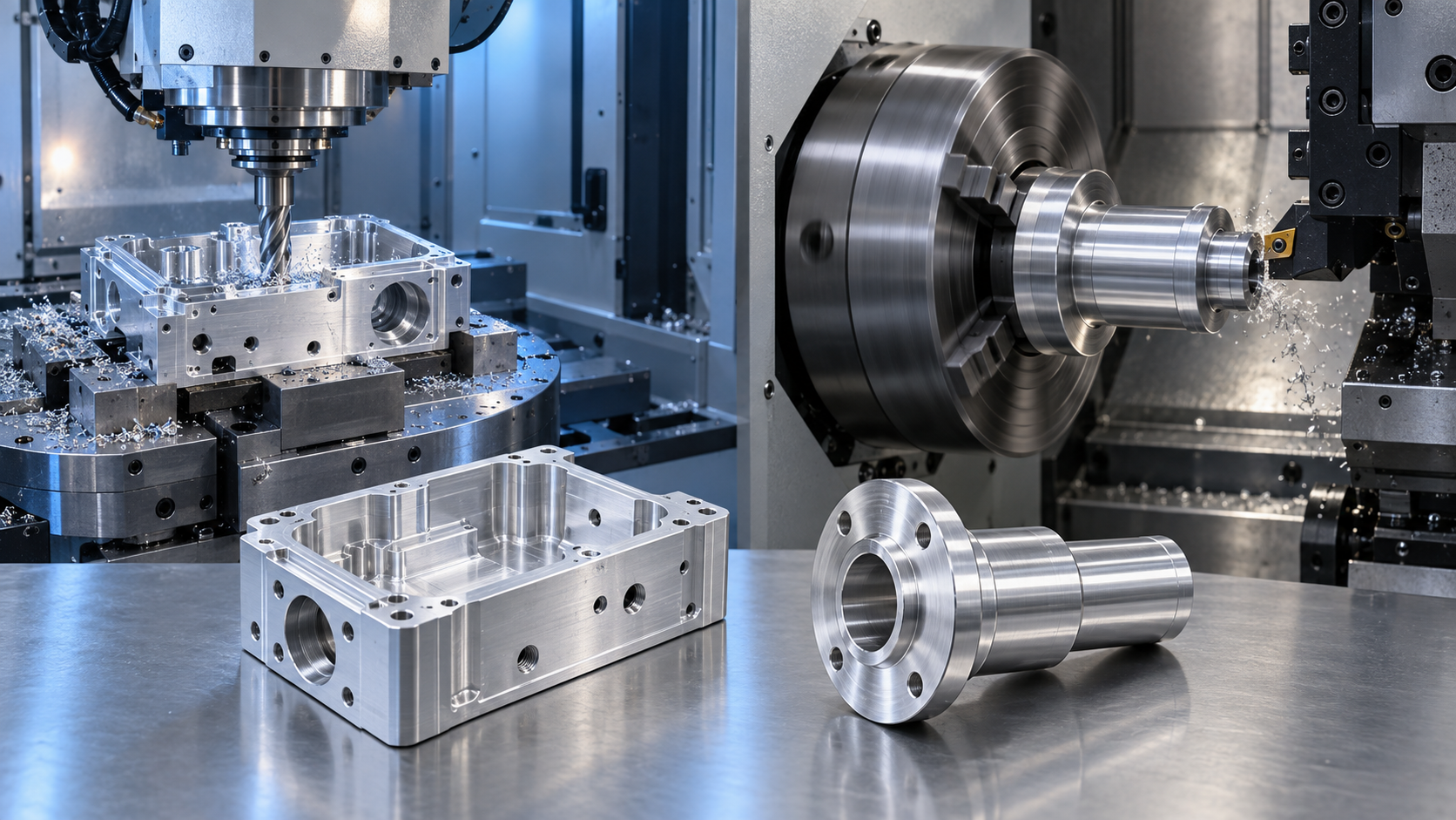
In CNC milling, a spindle rotates the cutting tool while the workpiece is held on a table or fixture. The machine positions the tool and workpiece along controlled axes to create faces, pockets, holes and contours. Autodesk’s CNC milling overview describes this rotating-tool arrangement and its use for non-cylindrical geometry.
In CNC turning, the spindle rotates the workpiece while a cutting tool follows the programmed profile. This naturally creates surfaces organized around the spindle axis. Autodesk’s turning process documentation identifies shafts, rings, wheels, bores and threads as typical rotational features.
This kinematic difference affects much more than the shape. It changes how stock is held, how cutting forces enter the part, which relationships can be created without reclamping, how chips leave the cut and which automation options make sense. BAOSONG’s aluminum CNC milling and aluminum CNC turning pages provide the corresponding service context.
CNC milling vs CNC turning comparison
The table is a process-screening guide, not a universal tolerance or cost specification.
| Decision factor | CNC milling | CNC turning | Buyer question |
|---|---|---|---|
| Dominant geometry | Prismatic, planar or freeform | Rotational about a centerline | Which geometry controls function? |
| Typical features | Faces, pockets, slots, bosses, contours and hole patterns | ODs, IDs, shoulders, tapers, grooves and concentric threads | Which features share a plane or an axis? |
| Workholding | Vises, fixtures, pallets, vacuum or custom supports | Chuck, collet, soft jaws, centers or guide-bushing arrangements | Can the part be held without distorting a functional surface? |
| Stock | Plate, block, extrusion, casting or other blank | Bar, tube, slug, forging or rotational blank | Does available stock fit the geometry and specification? |
| Critical relationships | Features linked through milling datums and setups | Diameters and faces created about the spindle axis | Which relationships should remain in one clamping? |
| Combined features | Rotary axes can index or continuously orient the work | Live tools and Y-axis capability can add milled features | Does one machine complete the part reliably? |
| Production driver | Pallets, multi-part fixtures and reduced setups | Bar feeding, part transfer and cycle consolidation | What is the accepted-part cost at the required mix? |
Confirm the part’s dominant geometry
A shaft with several diameters, a shoulder and a central bore is fundamentally a turning candidate. Milling the full outside cylinder from block stock would usually spend machine time approximating a shape that a lathe generates directly by rotation.
A rectangular manifold with ports on several faces, internal pockets and a gasket land is fundamentally a milling candidate. Although a lathe can create a bore, mounting that prismatic body for turning may add difficult balance, workholding and access problems.
Some parts are visually misleading. A round flange with an eccentric hole pattern is still likely to begin with turning because the bore, sealing face and outside diameter share an axis. A square housing with one important bearing bore may still begin with milling, followed by boring in the same setup that controls the bore’s location to the mounting datums.
Mark every feature on the model as rotational, planar, off-axis or freeform. Then identify which group carries the tightest functional relationships. That group usually points to the primary process.
Step 2: choose the process around critical relationships
“High precision” is not a process choice by itself. A diameter tolerance, runout requirement, position tolerance, flatness requirement and surface texture describe different functions. The process plan must show how the relevant datum references are established and maintained.
Turning can create multiple diameters, a bore and a face about one spindle axis without releasing the part. This can be valuable when coaxial behavior or face-to-axis relationships control the assembly. The result still depends on the chucking condition, tool deflection, thermal behavior, part rigidity and inspection method.
Milling can establish a primary mounting face, machine related pockets and locate hole patterns from that datum. Four- and five-axis strategies may reduce reclamping for multi-sided parts, but additional axes do not automatically improve every dimension. The fixture, calibration, tool access and sequence still matter.
ASME Y14.5-2018 (R2024) provides the rules for stating and interpreting GD&T. Projects using ISO GPS may instead reference standards such as ISO 1101:2017. Name the applicable system on the drawing and avoid mixing conventions by assumption.
Step 3: decide when to combine turning and milling
Many production components contain a rotational core and secondary non-rotational details. Examples include a shaft with a keyway, a threaded fitting with wrench flats, a flanged connector with a bolt pattern and a turned housing with radial ports.
Three route options should be compared:
- Turn, then mill on separate machines: flexible and widely available, but the transfer requires a locating strategy and may add queue time.
- Turning center with live tooling: keeps the work in one machine while rotating tools add holes, flats or slots within the machine’s axis and rigidity limits.
- Mill-turn or multi-task machining: combines broader turning and milling capability, potentially consolidating setups for complex components.
Autodesk’s machine-kinematics documentation distinguishes lathes with live tools from milling-based mill-turn arrangements. Machine labels alone are insufficient: ask for the proposed axis configuration, spindle transfer, accessible feature envelope and inspection plan.
Consolidation is valuable only if the chosen platform creates the needed features effectively. A simple turned pin with one cross-hole may be economical with a separate drilling fixture. A complex component whose critical features span both operations may gain more from one controlled setup. BAOSONG’s multi-axis aluminum machining page gives additional context for multi-sided features.
Step 4: prove the workholding strategy
Turning stock must be gripped securely while it rotates. Chuck jaws or collets need usable grip length and a surface that can transmit cutting force without unacceptable marking or distortion. Long, slender parts may need additional support, and tube-like components can deform under excessive clamping force.
Milled parts require a stable locating and clamping scheme that leaves cutting-tool access. A vise may suit a rigid block, while thin enclosures, castings and extrusions may need shaped supports or dedicated fixtures. Clamping a thin wall flat and then measuring it only while constrained can conceal free-state movement.
For either route, decide which stock surface is reliable enough to locate the first operation. Define how the opposite end or secondary side will be picked up. Soft jaws, fixture nests and probing can support repeatability, but they must be designed around the actual datum structure.
Step 5: check tool, chip and inspection access
Milling cutters need access to pockets, corners and side features. Deep narrow cavities can require long tools, which reduce rigidity and may affect chatter, finish and dimensional control. Internal square corners cannot be produced directly by a conventional round end mill; the design may need a radius, relief or another process.
Turning tools need clearance for shoulders, grooves and internal bores. Deep small bores or long internal features can require extended boring tools, while interrupted cuts and thin walls change the cutting condition. A CAD model that is rotationally symmetric can still be difficult to turn if there is no practical way to grip or support it.
Review tool entry, exit, chip evacuation, deburring and inspection access. An inaccessible feature can dominate cycle time even when most of the part matches the preferred process.
Step 6: model quantity and automation
Neither process has a universal quantity threshold. At low volume, available stock, programming and simple workholding may dominate. At repeat volume, bar feeders, sub-spindles, part catchers, pallet systems, multi-part fixtures and in-process checks can change the preferred route.
For turned parts made from bar, compare bar diameter with finished diameter and identify any secondary cutoff or back-working operation. For milled parts, compare the stock envelope, number of parts per setup, material removal and fixture loading. In both cases, quote the complete accepted component rather than a nominal hourly rate.
Separate one-time programming and fixture costs from recurring material, cutting, tool, inspection, finishing and packaging costs. Include realistic batch sizes and the expected mix of variants. A flexible process may be more valuable than the lowest modeled cycle when forecasts or revisions remain uncertain.
Include material, finish and burr control
Aluminum alloy and temper affect chip formation, strength, residual movement, surface response and stock availability. Select them from the component requirements, not from a generic statement that one grade is easiest to machine. BAOSONG’s aluminum alloy selection guide explains the wider material decision.
Turning produces a circumferential tool pattern on rotational surfaces; milling creates tool paths that depend on cutter and strategy. If appearance matters, identify cosmetic faces, directionality, acceptable tool transitions and reference samples. Connect machining with the required surface-finishing sequence.
Burrs can affect ports, threads, intersecting holes, sealing faces and assembly cleanliness. Mark critical edges and inaccessible intersections. Define whether edge condition is visual, dimensional or functional, and inspect it in the state delivered to assembly.
Step 7: validate the selected process
Inspection should follow the feature and datum strategy. A micrometer may suit a simple diameter, while runout, position, profile or multi-plane relationships can require different equipment, setups and analysis. NIST notes that measurement results are estimates and that uncertainty provides bounds for interpreting them in its dimensional-calibration guidance.
A useful control plan identifies:
- the operation that creates each critical characteristic;
- the datum condition used during machining and inspection;
- measurement equipment, calibration status and environment where relevant;
- first-article, in-process and final inspection stages;
- free-state or constrained-state requirements for flexible parts;
- records, sampling and traceability required by the customer.
See the BAOSONG aluminum CNC tolerance guide and quality overview for drawing-review inputs. Published guidance does not replace a project-specific capability and measurement review.
Four hypothetical selection examples
These examples illustrate the decision method and are not BAOSONG customer cases.
Stepped shaft with a bearing seat and center bore
Primary route: turning, because the important diameters, shoulder and bore share an axis. Secondary question: whether a keyway requires live-tool milling or a separate operation. Verify: size, face relationship, runout and the bearing-seat surface requirement in the specified datum setup.
Rectangular valve manifold with ports on three faces
Primary route: milling, because planes, pockets and off-axis ports dominate. Secondary question: whether multi-axis positioning reduces transfers while preserving access. Verify: mounting face, port position, intersecting passage condition, threads and cleanliness.
Flanged fitting with a bolt circle and wrench flats
Primary route: turning for the bore, sealing face, thread and OD. Secondary route: live-tool or separate milling for the bolt pattern and flats. Verify: which features must relate to the turned axis and whether the selected machine completes them without reclamping.
Thin electronic enclosure with a precision circular opening
Primary route: milling for the housing, sealing land and multi-face openings. Secondary question: bore the circular interface in the same stable setup as its mounting datum. Verify: free-state flatness, feature position, wall movement and finish condition.
Production route release checklist
| Gate | Check | Pass evidence |
|---|---|---|
| Feature map | Rotational, planar, off-axis and freeform features are assigned to an operation. | Reviewed process sequence |
| Datums | Critical diameters, faces and patterns remain connected through a controlled setup or transfer. | Datum and workholding plan |
| Machine | Axis configuration, live tools, sub-spindle, envelope and access match the proposed route. | Supplier machine and DFM response |
| Inspection | Measurement method, datum condition and free-state requirements fit each tolerance. | First-article inspection plan |
| Production | Stock, automation, deburring, finish, handling and accepted-part cost are included. | Comparable quotation and control plan |
| Change control | Machine, workholding, sequence or stock changes trigger documented review. | Approved revalidation rule |
Stop conditions: the CNC route is not ready
- The process was selected only because the part looks round or rectangular.
- Critical feature relationships and datum transfers are not identified.
- A live-tool or mill-turn label is accepted without confirming axes, access, envelope and spindle transfer.
- There is no stable grip or support strategy for thin, long or flexible stock.
- Deep features, internal corners, chip evacuation or intersecting-hole burrs have no plan.
- Quotations compare hourly rates while excluding stock yield, secondary operations, inspection, finish or accepted-part quantity.
- Inspection measures a constrained part although the drawing requires free-state acceptance.
Copy-ready CNC process RFQ checklist
- 2D drawing and 3D model with matching revisions;
- part function, mating components and critical feature relationships;
- alloy, temper, stock-form specification and approved substitutions;
- datum scheme, fits, threads, surface texture and edge requirements;
- features that must remain in one setup or share one axis;
- prototype, launch and repeat quantities with variant mix;
- finish, masking, cleanliness, inspection and reporting requirements;
- request for the proposed process sequence, workholding concept and assumptions.
Use BAOSONG’s engineering support and general CNC machining pages to frame the discussion. Send your drawings and quantity stages for a route review based on the finished component.
Frequently asked questions
Is CNC turning more accurate than CNC milling?
Neither is universally more accurate. Turning naturally controls rotational features about a spindle axis, while milling controls planar, positioned and multi-sided features through its datum and fixture strategy. Define the actual characteristic, tolerance and inspection condition.
Can a CNC lathe make flats and cross-holes?
A turning center with suitable live tooling and axes may create them. Confirm the machine configuration, feature access, tool rigidity and whether completing them in one machine improves the critical relationships or total cost.
Can a CNC mill produce a round shaft?
It can generate cylindrical geometry with rotary strategies or interpolate circular features, but a lathe is usually the more direct starting point for a mainly rotational shaft. The exceptions depend on part size, availability, secondary features and workholding.
Should a turned part be finished on a mill?
Only when non-rotational features require it and a combined-machine route is not preferable. Plan how the mill locates from the turned geometry so position and orientation requirements survive the transfer.
What information most affects the process choice?
The 3D geometry starts the review, but the drawing completes it. Critical datums, feature relationships, stock requirements, quantities, finish, inspection and revision status often determine whether milling, turning or a combined route is practical.
Recommended Downloads for CNC Machining Design
Use these BAOSONG references to improve tool access, feature geometry, practical tolerances and CNC process planning before release.
- Aluminum CNC Machining Design Guide (PDF)
- CNC Milling Guide: Pockets, Walls, Corners & Tool Access (PDF)
- CNC Turning Guide: Diameters, Threads & Concentric Features (PDF)
- CNC Machining Tolerance Guide (reference sheet)
- Aluminum Part Design Checklist (editable Excel)
Need help reviewing a machined part or feature stack? Contact BAOSONG Precision.
