
Quick answer: which CNC axis configuration should you choose?
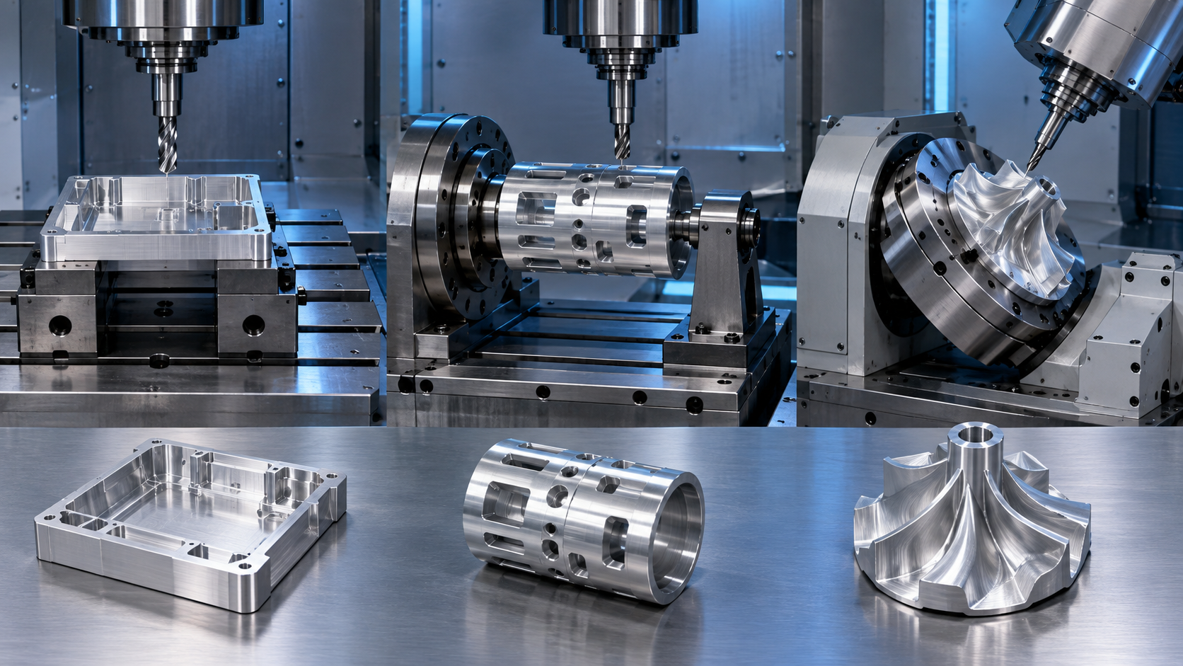
Choose 3-axis CNC machining when the important features are accessible from a small number of fixed directions and simple, stable fixtures can locate the part. Choose 4-axis machining when one rotary axis can present several sides or machine features around a cylinder. Choose 5-axis machining when the part needs two independent angular orientations, compound-angle access, or a continuously changing tool direction.
Five-axis is not automatically the best or most accurate option. The correct route is the minimum machine capability that can create the required geometry and critical feature relationships with a reliable setup, practical tools, suitable inspection and competitive accepted-part cost.
In any 3-axis vs 4-axis vs 5-axis CNC machining comparison, distinguish indexed positioning from simultaneous cutting. A five-axis machine performing 3+2 machining locks its rotary axes before a three-axis cut. Simultaneous five-axis machining moves the linear and rotary axes together while cutting.
Seven-step CNC axis selection process
| Step | Decision | Required output |
|---|---|---|
| 1 | Classify feature directions and functional datums | Access and relationship map |
| 2 | Test a 3-axis setup route first | Minimum-axis baseline |
| 3 | Check whether one rotary axis solves the problem | 4-axis index/support plan |
| 4 | Separate 3+2 positioning from simultaneous 5-axis | Named toolpath strategy |
| 5 | Evaluate setup reduction and kinematic error | Datum, calibration and inspection plan |
| 6 | Simulate tool, holder, fixture and machine envelope | Machine-specific access evidence |
| 7 | Compare accepted-part cost and validate | Complete quotation and production release plan |
Step 1: define what the axis count means for this part
Most CNC milling descriptions begin with three linear directions: X, Y and Z. A fourth axis adds controlled rotation around one line. A fifth axis adds another independent rotation. The physical motion can come from the table, the spindle head or a combination, so two machines described as “five-axis” may have different envelopes, pivot points, rigidity and access.
Autodesk’s CNC machining overview distinguishes three-axis, four-axis and five-axis strategies and notes that four-axis milling adds one rotational axis. Its machine-kinematics documentation shows why the same programmed part can require different physical motions on head-head, table-table or mixed configurations.
Axis count describes available movement, not the number of axes that must move at every moment. A four-axis machine may index, lock and perform a three-axis cut. A five-axis machine may use 3+2 positioning for most of the part and reserve simultaneous motion for a small surface. Ask how the proposed toolpath uses the machine, not only which label appears on the quotation.
3-axis vs 4-axis vs 5-axis comparison
This matrix is a selection aid. Actual suitability depends on the part, machine configuration, workholding, material and drawing.
| Decision factor | 3-axis machining | 4-axis machining | 5-axis machining |
|---|---|---|---|
| Controlled motion | Three linear axes | Three linear axes plus one rotary axis | Three linear axes plus two rotary axes |
| Natural geometry | Plates, housings, pockets and features from fixed directions | Features around a cylinder, indexed sides and wrapped geometry | Compound angles, under-access features and continuously oriented surfaces |
| Typical strategy | One orientation per setup | Indexed positions or simultaneous rotary cutting | 3+2 positioning or simultaneous five-axis cutting |
| Main advantage | Rigid, accessible and economical for suitable geometry | Rotary access can reduce manual repositioning | Broad tool orientation and potential setup consolidation |
| Primary risk | Too many transfers for multi-sided features | Centerline, support, cable travel and rotary calibration | Collision, kinematic error, singularity, envelope and programming complexity |
| Key evidence | Setup and datum plan | Rotary-axis use and support plan | 3+2 versus simultaneous toolpath and machine simulation |
Step 2: test whether 3-axis machining is sufficient
Three-axis machining remains effective for many precision aluminum components. A plate with pockets and a hole pattern, a housing open from the top, a fixture block or a bracket with features accessible from two or three orthogonal directions may need no rotary cutting.
The process can use simple workholding, short rigid tools and a familiar inspection approach. If a second orientation is needed, a well-designed locating fixture may produce the required feature relationship without the programming and rotary-envelope demands of a higher-axis machine.
Choose 3-axis when:
- the dominant features are accessible along fixed tool directions;
- the part can be located repeatably for any secondary side;
- tool reach is practical without severe holder interference;
- the required relationships do not suffer from planned transfers;
- production fixtures or pallets make the complete route efficient.
Do not reject 3-axis simply because a part has more than one machined side. The meaningful question is whether additional orientations create unacceptable setup time, datum transfer or variation. Review the finished-part route through BAOSONG’s aluminum CNC milling context rather than choosing by axis count alone.
Step 3: check whether a fourth axis adds useful access
A fourth axis usually rotates the workpiece around one controlled axis. It can index a component to several angular positions or rotate during cutting. This is particularly useful for a cylindrical body with radial holes, flats, windows, grooves or repeated features around its circumference.
Four-axis fixtures can also hold several components around a tombstone or rotary device, presenting new work faces to the spindle. The benefit may come from reduced handling and improved access rather than complex contouring.
Check whether the part is supported adequately as it rotates. Long components may need a tailstock or another support strategy. Clamps and fixtures must stay clear of the tool at every indexed angle. The rotary centerline, work offset and machine travel must remain compatible with the part and holder.
Machine-tool builders distinguish single-axis rotary products from dual-axis five-axis tables. A machine-specific capability still needs verification; the presence of a rotary device does not prove that every four-axis toolpath, part diameter or tolerance relationship is feasible.
Step 4: choose 3+2 or simultaneous 5-axis machining
This is the most important distinction in a five-axis RFQ.
In 3+2 machining, the two rotary axes orient the workpiece or tool, then hold that orientation while the three linear axes cut. This can reach angled holes, side pockets and multiple faces while using familiar three-axis toolpaths. It can also allow shorter tools by aiming the spindle toward the feature.
In simultaneous five-axis machining, linear and rotary axes move together during the cut. The tool direction changes along the path. This is useful for impellers, blades, sculpted surfaces, swarf cutting, compound contours and features whose access changes continuously.
Autodesk’s five-axis machining guide describes both modes. HEIDENHAIN’s rotary-axis accuracy paper likewise defines 3+2 as rotary axes positioned and held before cutting, while simultaneous five-axis interpolates three linear and two rotary axes together.
A part made on a five-axis machine is not necessarily a simultaneous-five-axis part. The selected strategy should appear in the process plan because programming, postprocessing, simulation, tool orientation and validation differ.
Step 5: evaluate setup reduction and kinematic error
Additional axes can improve a feature relationship when they eliminate a manual re-clamp or allow several features to be created from one controlled setup. They can also add error sources: rotary-axis positioning, pivot calibration, thermal behavior, workholding location, transformation settings and the interaction of linear and angular error at the tool tip.
HEIDENHAIN notes that rotary-axis positioning errors have a direct influence on the workpiece during five-axis machining. Siemens’ SINUMERIK simultaneous-milling manual explains that tool orientation depends on machine kinematics and must be programmed alongside tool-tip position.
Precision must be tied to the drawing:
- size: a width, thickness or diameter;
- form: flatness, straightness or profile;
- orientation: perpendicularity, parallelism or angular control;
- location: position of holes, bores or surfaces relative to datums;
- rotation-related behavior: runout or features tied to an axis.
Use the project-specified GPS or GD&T system. ASME Y14.5-2018 (R2024) provides the current listed North American language for stating and interpreting GD&T. A higher axis count cannot correct an ambiguous datum scheme.
Setup reduction matters when relationships cross faces
Every time a part is removed and located again, the process must transfer the intended relationship through the locating surfaces and fixture. That transfer can be stable and measurable, but it must be designed.
Suppose a housing has a mounting base, an angled connector face and a bore that must relate to both. A 3-axis route may machine each orientation in a separate fixture. A 3+2 route may orient the workpiece and machine those features without releasing it. The latter can simplify the relationship, provided the rotary calibration, workholding and tool access are suitable.
Setup count alone is not a quality metric. One overloaded fixture with weak support can be less reliable than two controlled operations. Compare:
- how each operation establishes its datums;
- which critical features stay in the same clamping;
- whether cutting forces or rotary orientation distort the part;
- how the opposite side and residual stock are reached;
- how inspection recreates the specified datum reference frame.
Step 6: simulate tool access, reach and surface geometry
Tilting the tool or part can shorten tool projection and avoid holder interference in deep or angled regions. A shorter assembly is generally more rigid, but the actual improvement depends on tool diameter, holder, material, engagement and machine configuration.
Simultaneous five-axis motion can maintain a changing approach to a curved surface, but it also requires controlled tool-axis behavior. Sudden rotary motion, poor surface parameterization or a postprocessor mismatch can affect marks and motion. CAM verification should include the tool, holder, fixture, stock, machine limits and safe retracts.
For prismatic features, a simpler fixed-axis path may provide the most stable cutting condition. Use simultaneous motion where geometry or access requires it, rather than applying it to every surface because the machine can move that way.
Work envelope and fixture clearance can eliminate an option
Rotating a part changes the space it occupies. A component that fits inside a machine at zero degrees may hit the spindle, enclosure, trunnion, table, fixture or toolholder when tilted. The usable machining envelope is therefore smaller and more complex than the nominal axis travels suggest.
Before release, simulate the complete setup and check:
- part sweep at every rotary orientation;
- fixture, clamp and tailstock clearance;
- tool and holder reach for roughing and finishing;
- rotary limits, unwind behavior and possible singular regions;
- chip evacuation and coolant access;
- load, balance and support through each orientation.
Machine model accuracy and postprocessor validation are part of the system. A collision-free CAM toolpath without the correct machine, holder and fixture model is incomplete evidence.
Step 7: compare complete accepted-part cost
Three-axis machine time may be less expensive per hour, yet multiple fixtures, transfers and inspection stages can raise the completed-part cost. Five-axis time may carry a higher rate, but setup consolidation, shorter tools or improved access can reduce total work. Four-axis can be an efficient middle route for cylindrical or indexed features.
Do not use a universal axis-count price multiplier. Ask suppliers to separate:
- programming, postprocessor and simulation effort;
- fixtures, soft jaws and rotary workholding;
- number of operations and manual transfers;
- roughing, finishing and deburring time;
- first-article and recurring inspection;
- expected batch quantity, loading plan and automation;
- risk attached to design revisions.
Compare quotations for the same accepted component, material, finish, records and delivery scope. BAOSONG’s general CNC machining and multi-axis aluminum machining pages provide relevant manufacturing context without asserting that one axis count is always preferable.
Production release checklist
- Identify the functional datums. Determine what locates the component in its assembly.
- Classify the critical features. Mark fixed-direction, radial, indexed-angle, compound-angle and continuous-contour features.
- Test tool access. Include the toolholder, fixture and stock, not only the nominal cutter centerline.
- Map possible setups. Show which features are created in each clamping and how the datum is transferred.
- Choose the minimum suitable motion. Start with 3-axis, then add one or two rotary axes only where they solve a documented access or relationship problem.
- Confirm machine-specific limits. Check envelope, axis configuration, calibration, rotary load, tooling and postprocessor.
- Plan verification. Match inspection to the drawing characteristic and manufacturing datum condition.
- Compare accepted-part cost. Include fixtures, transfers, inspection, finishing and quantity.
For tolerance planning, see BAOSONG’s aluminum CNC machining tolerance guide. For material choices, use the aluminum alloy selection guide. Neither replaces review of the specific drawing and machine route.
Four hypothetical examples
These examples illustrate the method and are not BAOSONG customer cases.
Flat electronics housing with top-side pockets
Starting route: 3-axis machining, followed by a controlled second-side operation if needed. Reason: the functional geometry is prismatic and accessible from fixed directions. Verify: base flatness, pocket depth, hole position and free-state condition after unclamping.
Cylindrical sleeve with windows around the circumference
Starting route: 4-axis indexed or simultaneous rotary machining. Reason: one rotary axis presents repeated radial features while preserving their angular relationship. Verify: centerline setup, support, window position and deburring of intersections.
Bracket with angled bores on several faces
Starting route: compare 3+2 five-axis positioning with dedicated 3-axis fixtures. Reason: two rotary axes can orient each bore toward the spindle without simultaneous contouring. Verify: bore position and orientation to the functional datums, rotary clearance and inspection access.
Impeller with continuously curved blades
Starting route: simultaneous five-axis machining. Reason: tool orientation must change along the curved blade and between restricted surfaces. Verify: tool-axis strategy, collision simulation, remaining stock, surface profile and the measurement method for complex geometry.
Stop conditions: the axis strategy is not ready
- The quotation says only “five-axis” without identifying 3+2 or simultaneous motion.
- The proposed route uses more axes but does not solve a documented access, setup or relationship problem.
- Machine head/table configuration, rotary limits, pivot calibration or usable envelope are unknown.
- The simulation omits the real stock, fixture, clamps, holder, tailstock or full rotary sweep.
- Critical features cross setups, but the datum transfer and inspection condition are undefined.
- One-setup production is claimed although a clamping surface or inaccessible backside still requires another operation.
- Hourly machine rates are compared without programming, fixtures, inspection, finishing and accepted-part yield.
Copy-ready multi-axis CNC RFQ checklist
- matching-revision 2D drawing and 3D model;
- functional datums, assembly interfaces and critical characteristics;
- alloy, temper, stock form and approved substitutions;
- features that must remain in one setup or share a controlled relationship;
- surface texture, edge, finish, masking and cosmetic requirements;
- prototype, launch and repeat quantities with variant mix;
- inspection, traceability and report requirements;
- a request for the proposed axis strategy, setup map and assumptions.
BAOSONG’s engineering support, quality overview and surface-finishing resources outline useful inputs for the review. Send the drawing and quantity stages to discuss a suitable machining route and validation scope.
Frequently asked questions
Is 3+2 machining the same as five-axis machining?
It uses a machine with five controlled axes, but it is positional machining: the rotary axes orient and lock before the three linear axes cut. Simultaneous five-axis changes tool orientation during the cut.
Does a five-axis machine make every part in one setup?
No. Clamping surfaces, inaccessible backsides, stock removal and inspection may still require another operation. The aim is a stable process that controls the critical relationships, not a forced one-setup claim.
Is four-axis machining only for round parts?
No. A rotary axis can index prismatic parts, fixtures or multiple workpieces as well. It is especially natural for circumferential features, but its value comes from one controlled rotation and useful access.
Which axis configuration provides the tightest tolerance?
No axis count guarantees a tolerance. Machine condition, kinematics, calibration, tools, workholding, temperature, feature geometry and measurement all contribute. Specify the functional characteristic and review the complete process.
When should I pay for simultaneous five-axis machining?
Use it when continuously changing tool orientation solves a real geometry or access problem, such as complex blades, compound contours or restricted surfaces. Angled but fixed-direction features may need only 3+2 positioning.
Recommended Downloads for CNC Machining Design
Use these BAOSONG references to improve tool access, feature geometry, practical tolerances and CNC process planning before release.
- Aluminum CNC Machining Design Guide (PDF)
- CNC Milling Guide: Pockets, Walls, Corners & Tool Access (PDF)
- CNC Turning Guide: Diameters, Threads & Concentric Features (PDF)
- CNC Machining Tolerance Guide (reference sheet)
- Aluminum Part Design Checklist (editable Excel)
Need help reviewing a machined part or feature stack? Contact BAOSONG Precision.
