
Quick answer: what makes an aluminum server frame or GPU enclosure production-ready?
A production-ready aluminum server frame or GPU enclosure must carry the installed mass without losing connector alignment, move cooling air through the intended components, provide controlled electrical-bonding paths and allow modules to be assembled and serviced repeatedly. These requirements must be designed as one mechanical system.
Start with the rack and platform interfaces, component mass and center of gravity, airflow or liquid-cooling architecture, insertion forces, cable routes and maintenance sequence. Then establish structural datums, rails, card guides, panel joints and machining features around those boundaries. A rigid frame that blocks airflow or an open enclosure that twists during service is not a successful design.
The released drawing should distinguish functional interfaces from clearance dimensions and cosmetic surfaces. Verify the assembled chassis with representative GPUs, power hardware, cooling parts and cables under normal and degraded operating conditions; a frame inspection alone cannot prove system alignment, thermal performance or EMC compliance.
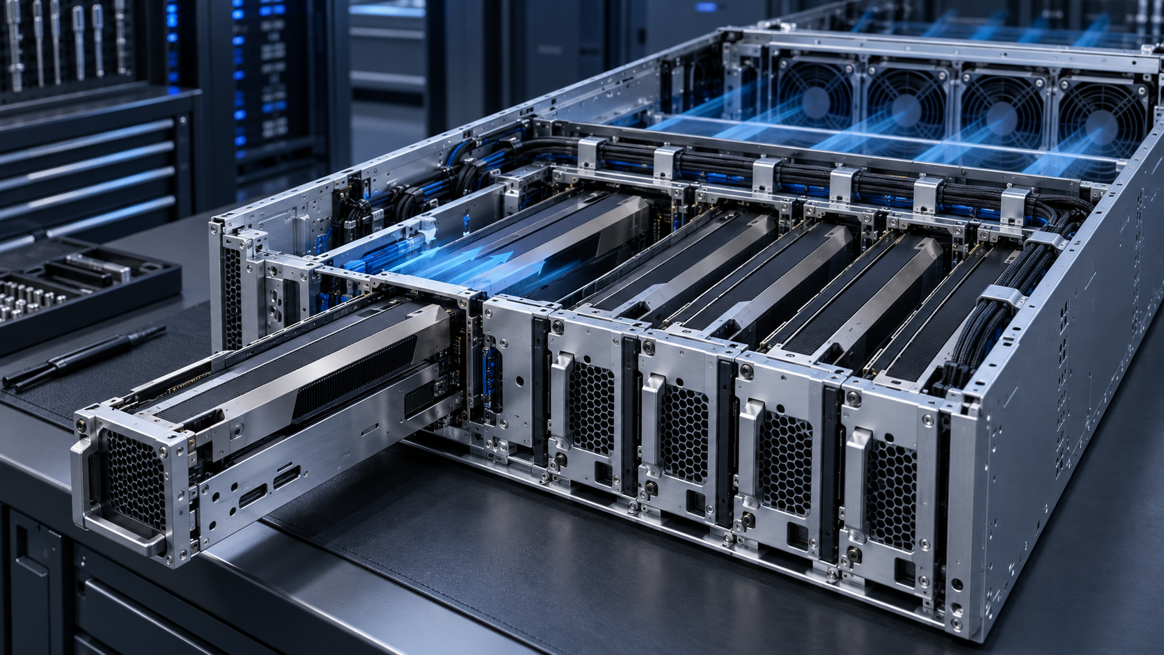
Treat the enclosure as a system of interfaces
Use this sequence before dividing the chassis into individual parts:
- Freeze platform interfaces. Record rack rails, module envelopes, blind-mate connectors, power, cooling, cables, grounding and service clearances.
- Build structural load cases. Include installed mass, tray insertion, extended service, lifting, transport shock and vibration.
- Map airflow and liquid paths. Allocate open area and pressure drop and define every duct, fan wall, cold plate, hose and manifold interface.
- Select the component architecture. Assign extrusions, sheet, plate, machining, joints, finishes and bonding lands to clear functions.
- Validate the assembled chassis. Test alignment, insertion, cooling, bonding and durability with representative hardware and cables.
A GPU server enclosure connects the data-center rack to processors, accelerator trays, fans, power supplies, backplanes, network interfaces and cooling hardware. It also has to survive manufacture, transport, installation and repeated service. Define each boundary before optimizing individual brackets or panels.
Berkeley Lab’s open specification for a liquid-cooled server rack connects rack mechanics, wetted-material compatibility and cooling interfaces across equipment generations. Its liquid-cooling requirements white paper also places equipment interfaces inside the wider facility and IT system. These resources demonstrate an interface-led approach; a specific form factor applies only when named by the customer.
Create an interface-control document for rack mounting, module envelopes, datum targets, connector float, blind-mate engagement, fan walls, ducts, cold plates, manifolds, cable exits, grounding points and service clearances. Freeze these interfaces by revision so suppliers can evaluate changes without relying on an uncontrolled 3D model.
Build the structural load case before selecting sections
| Load case | Inputs to define | Possible failure |
|---|---|---|
| Installed operation | All module masses, rail support, fan vibration and cable reactions | Sag, resonance, connector misalignment or acoustic noise |
| Tray insertion | Handle force, guide contact, connector force and allowed user load | Racking, guide wear, incomplete engagement or board stress |
| Partial service | Extended tray position and remaining support points | Tipping, rail overload or permanent frame set |
| Transport | Packaging restraint, shock spectrum, vibration and orientation | Fastener loosening, fretting, bent panels or displaced modules |
| Rack installation | Lifting points, slide engagement and technician handling | Local yielding, trapped fingers or uncontrolled drop |
Separate strength from stiffness. A member can remain below yield while deflecting enough to compromise a blind-mate connector or cold-plate contact. Include joints in the model because screws, tabs, rivets and extruded corner connections determine real load transfer. Check local bearing and pull-through around thin panels as well as global frame twist.
IEC 61587-1:2022 covers environmental requirements, test setups and safety aspects for empty cabinets, racks, subracks and chassis, including static and dynamic loading with representative dummy loads. Use the customer’s applicable standard and performance class to build the qualification plan instead of assuming one generic test proves every deployment.
Design datums around connectors and cooling interfaces
The functional datum scheme should follow the assembly chain. A rack rail may locate the chassis; an internal frame locates the baseboard; the baseboard locates connectors; card guides position the GPU tray. Tolerance loops across these interfaces control insertion force and electrical engagement. Do not dimension each part from an unrelated cosmetic edge.
Define which features locate, which fasten and which provide clearance. Use controlled float where it helps blind-mate connectors absorb assembly variation, but prevent uncontrolled motion that can fret contacts or reduce thermal-interface pressure. Check maximum-material conditions and worst-case assembly, including finish thickness and supplier-to-supplier component variation.
Use ASME Y14.5-2018 (R2024) where the drawing invokes that GD&T system. Align machined rails and mounting features with BAOSONG’s guidance on practical aluminum CNC tolerances. Tighten only the features whose variation affects fit, cooling contact, signal connection or service.
Choose extrusions, plate and sheet for different jobs
Aluminum extrusion is useful for rails, side beams, card guides, stiff perimeter members and repeated channels. It places material along a constant cross section and can integrate grooves, screw ports, alignment lips or cable features. Sheet or thin plate is often more efficient for broad covers, airflow partitions and shields. Machined plate suits local high-load or precision interfaces.
A hybrid architecture can use extruded structural rails, formed covers and CNC-machined connector or cold-plate supports. Review BAOSONG’s custom aluminum extrusion design guide and profile manufacturability guide before freezing deep channels, thin walls or inaccessible screw ports.
For precision features, extrusion plus CNC machining can establish connector planes, rail datums and hole patterns after the profile is cut. Preserve enough stock for cleanup and design fixtures around stable datum surfaces. Avoid asking extrusion tolerances to control interfaces that genuinely need a machined relationship.
Cooling starts with open area and pressure drop
Every panel, fan guard, card guide, cable bundle and perforation contributes to system impedance. A large apparent vent can still have poor effective open area or create a high-velocity jet that bypasses components. Map the complete path from equipment inlet through GPUs, memory, power conversion and fans to exhaust.
ASHRAE Handbook Chapter 20 identifies the equipment inlet as a common environmental reference and notes that component selection, heat sinks, fans and airflow management drive server thermal design. Record local inlet temperature and pressure rather than using the room set point as a substitute.
Design seals and baffles so air cannot take an easier path around the GPU heat sinks. Use blanking elements for optional modules, and confirm that cable service loops do not collapse the intended plenum. Model fan operating points with the actual system resistance. Test fully populated, partially populated and defined fan-failure configurations where those states are allowed.
Coordinate liquid cooling with the frame
For direct-to-chip liquid cooling, the frame must locate manifolds, hoses, drip-management features and cold-plate connections without transmitting unacceptable loads to boards or packages. Define dry-break access, bend radius, mating direction, allowable connector load, leak-detection route and service order. Protect hoses from sheet edges and prevent a removable tray from pulling on a fixed manifold.
A cold plate may reduce the heat rejected to server air, but power supplies, memory, networking, storage and voltage regulators can still need airflow. The enclosure therefore remains a thermal component. Use the air-side heat-sink design framework together with live platform documentation to define the actual split between air and liquid heat removal.
Design for repeatable assembly and service
| Feature | Design control | Evidence |
|---|---|---|
| Tray guides | Lead-in, wear surface, anti-misinsert feature and retention | Repeated insertion test and alignment inspection |
| Fasteners | Captive hardware, tool access, torque range and locking method | Assembly audit and vibration qualification |
| Blind mates | Datum chain, float, engagement stroke and connector protection | Worst-case tolerance build and cycle test |
| Cables | Bend radius, clamp spacing, abrasion protection and service loop | Routing inspection in every allowed configuration |
| Covers | Positive location, bonding contact, captive release and no loose hardware | Fit, ground-bond and service-time verification |
The 2023 OCP circular-economy-ready server chassis specification provides a concrete example of reusable lids, fan caddies, drive caddies and reduced-fastener assembly. Its dimensions and architecture are platform-specific, but the design lesson is broadly useful: service steps, part reuse and hardware count should be considered before tooling.
Use poka-yoke geometry so technicians cannot install a module in the wrong orientation. Provide accessible handles and stable intermediate positions. Captive fasteners reduce loose-part risk, but they still require retention validation. Mark service parts in documentation rather than adding uncontrolled labels that can obstruct vents or grounding contacts.
Plan electrical bonding and EMC at every seam
An aluminum enclosure can contribute to electromagnetic shielding, but apertures, seams, coating, fasteners and cable penetrations govern the final result. Define the intended bonding path between covers, frame, rack interface and protective earth. Anodized surfaces are electrically insulating unless contacts are masked, penetrated or otherwise engineered.
Specify bare contact lands, conductive gaskets, fastener spacing and surface preparation where needed. Keep ventilation and EMC requirements in the same design review because reducing aperture size or adding a mesh changes pressure drop. Compliance belongs to the assembled electronic product and its test configuration; a metal panel by itself cannot guarantee it.
Control finish, corrosion and cosmetic expectations
Use finish to meet corrosion, wear, electrical and appearance needs. Clear or black anodizing may suit exposed structural parts, while conversion coatings or masked contact areas may be selected for bonding. Define whether critical dimensions apply before or after coating and protect threads and precision fits where buildup matters.
BAOSONG’s anodizing service overview and surface-finishing capabilities support early decisions. For visible front panels, establish an approved sample, viewing conditions, surface class and allowed contact marks instead of relying on a color name alone.
Validate the assembled enclosure, not just its parts
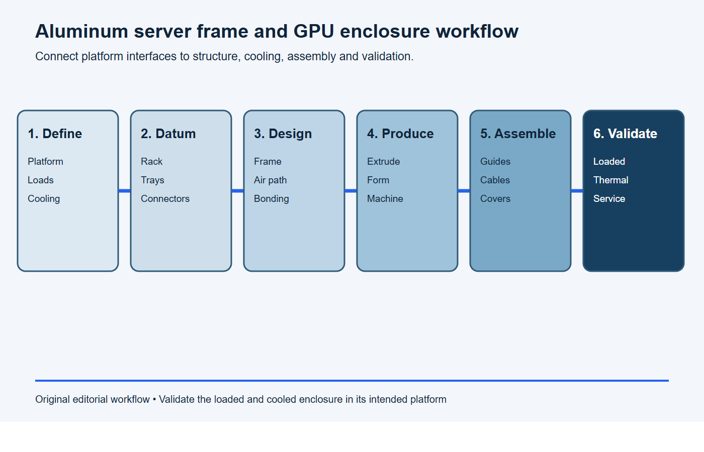
Start with dimensional inspection of critical datums, rack interfaces, tray paths and connector planes. Then assemble representative hardware and check insertion force, cover fit, cable clearance and cooling contacts. Measure pressure drop, temperature and fan behavior with production-representative perforations, seals and filters.
Use shock and vibration tests that reflect the declared transportation and use condition. Measure response at vulnerable modules as well as the chassis input, because resonance can amplify local motion. Document fixture, orientation, dummy mass, fastener state and acceptance limits. IEC 61587-1 provides a relevant empty-enclosure framework; product and customer standards may add powered-system, safety, EMC and transport requirements.
Record measurement uncertainty and inspection method. NIST’s resource on uncertainty in dimensional calibration reinforces why a tolerance decision needs a capable measurement process. Retain first-article results, assembly deviations and thermal correlation data against the controlled revision.
RFQ checklist for aluminum server frames and GPU enclosures
Paste this scope into the RFQ and attach the controlled assembly model, interface-control documents, load cases and cooling data.
RFQ scope: Please quote [server-frame or enclosure revision] for [prototype quantity] and [annual volume]. The chassis fits [rack/interface standard], supports [installed modules and mass], uses [air/liquid cooling architecture], and must withstand [operation, service and transport load cases]. Quote the proposed extrusion, sheet and machined-part split, alloys, joints, finishes, tooling, unit price, lead time and capacity. List every assumption and deviation.
Required evidence: Provide material traceability, component and assembled dimensional inspection, connector and tray-alignment results, joint/fastener controls, finish and bonding records, airflow or liquid-interface verification, first-article documentation, packaging controls and change-notification triggers. Identify powered thermal, EMC and system qualification outside the supplier scope.
- Rack standard, equipment height, depth, rail interface and maximum installed mass.
- Controlled 3D model and 2D drawings with the functional datum scheme.
- GPU, board, fan, power, connector and cooling component envelopes.
- Normal, insertion, extended-service, transport and lifting load cases.
- Airflow direction, allowable pressure drop, inlet conditions and fan curves.
- Liquid connections, hose loads, leak controls and service sequence where applicable.
- Material, temper, extrusion or sheet specifications and finish requirements.
- Electrical-bonding lands, EMC interfaces, grounding hardware and masked zones.
- Critical dimensions, inspection methods, samples and traceability.
- Prototype and production quantities, packaging and qualification plan.
Stop conditions: the server enclosure is not ready for release
Pause tooling or production release if any condition below remains unresolved.
- rack, tray, board, connector or cooling interface revisions do not match;
- installed, insertion, extended-service, lifting or transport loads are missing;
- connector float and datum chains have no worst-case assembly analysis;
- airflow open area, pressure-drop budget, bypass and fan operating points are undefined;
- cold-plate hoses, manifold connections or service loads lack controlled interfaces;
- electrical bonding lands, coatings, fastener spacing or EMC seams are unresolved;
- service steps cannot return ducts, cables, covers and hardware to a repeatable state;
- part inspection is being used as proof of assembled thermal, EMC or transport performance.
Frequently asked questions
Is aluminum strong enough for a GPU server chassis?
It can be when the alloy, section geometry, joints and load cases are engineered together. Check stiffness, connector alignment, local bearing and transport loads as well as material strength. Validate the loaded assembly rather than relying on an alloy label.
Should a GPU enclosure use extrusion or sheet metal?
Many effective designs use both. Extrusions suit repeated rails, guides and stiff members; sheet suits broad covers, partitions and vents; machining establishes selected interfaces. Compare total assembly performance and cost rather than forcing one process across every component.
Does an aluminum enclosure guarantee EMC shielding?
No. Shielding depends on seams, apertures, coatings, bonding, gaskets, fasteners, cables and the complete electronics configuration. Define and test the assembled product against its applicable requirements.
How should cooling and serviceability be balanced?
Design the service path into the airflow architecture. Use removable ducts, captive hardware and controlled cable routes that return to a repeatable position. Verify cooling after representative service cycles so access features do not create bypass or loose seals.
Request a server-frame manufacturing review
BAOSONG supports projects combining aluminum extrusion, CNC machining and finishing. Send the controlled platform interfaces, drawings, load cases, cooling architecture, bonding requirements, inspection plan and production quantities through the contact page for a manufacturability and quotation review.
Recommended Downloads for Aluminum Extrusion Design
Use these BAOSONG references to set profile geometry, wall thickness, tolerances and downstream CNC features before releasing an extrusion design.
- Custom Aluminum Extrusion Design Guide (PDF)
- Wall Thickness and Tolerance Guide (PDF)
- CNC Machining Guide for Aluminum Extrusions (PDF)
- Aluminum Alloy Comparison Chart (editable Excel)
Need help checking an extrusion profile or manufacturability risk? Contact BAOSONG Precision.
