
Quick answer: what makes an aluminum heat sink work in a high-density compute system?
An aluminum heat sink succeeds in a high-density compute system only when its thermal resistance, pressure drop, mounting interface and server airflow are designed together. Begin with the device heat map and allowable case temperature, define the air entering the sink and the fan operating point, then size the base and fins around that boundary condition.
More fins do not automatically produce more cooling. Closely spaced fins add surface area, but they also resist airflow and may push air around the sink. Likewise, a highly conductive alloy cannot compensate for a poor thermal interface, weak base spreading, recirculated exhaust air or an uneven clamp load.
The production drawing should therefore control the functional stack: mounting datums, base contact zone, interface material, fastener or spring loads, keep-outs, airflow direction and inspection state. Thermal simulation helps compare concepts, but qualification should use representative hardware in the intended chassis with realistic inlet conditions and system power.
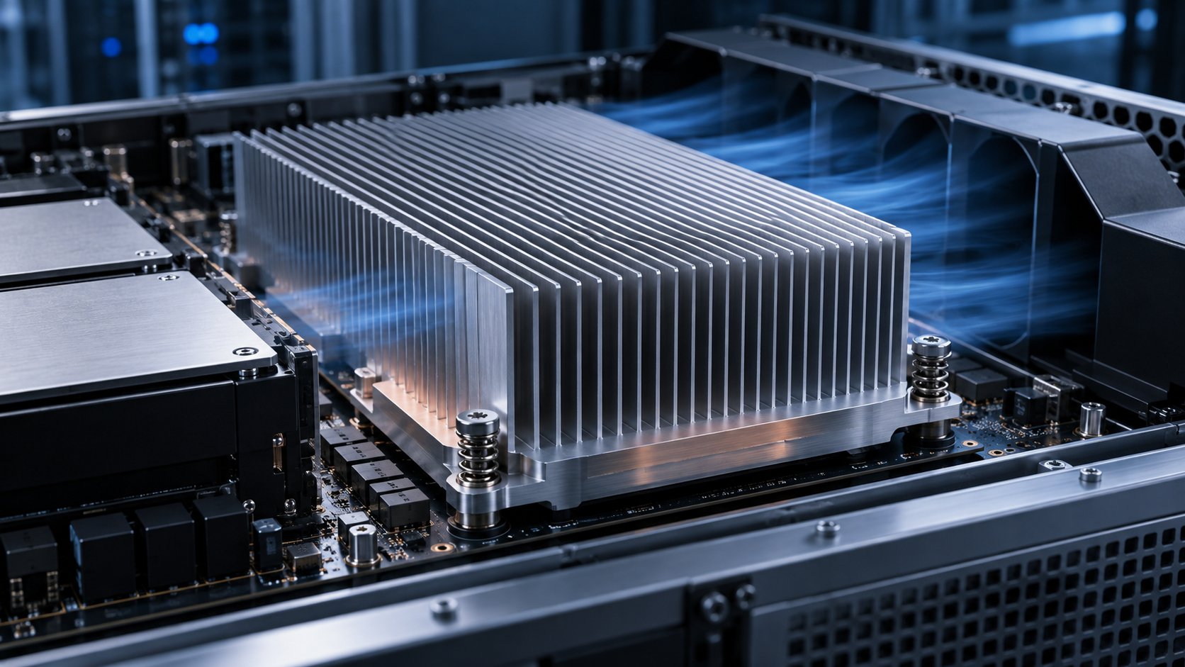
Define the complete thermal path before designing fins
Use this sequence before selecting fin pitch or alloy:
- Freeze the heat source. Record the device footprint, spatial heat map, power states, allowable case or junction temperature and nearby heat sources.
- Define the air boundary. Use local inlet temperature, fan curve, available pressure, chassis impedance, ducting and bypass paths.
- Allocate the thermal-resistance budget. Divide the allowable rise among TIM contact, base spreading, fins and heated exhaust air.
- Select geometry and process together. Compare extrusion, bonded or skived fins, machining and hybrid construction against fin density, volume and tolerances.
- Validate in the intended chassis. Measure temperature, airflow, pressure, acoustic and mechanical behavior with production-equivalent mounting and system power.
A useful heat-sink specification begins at the semiconductor junction and ends at the air leaving the server. Between those points are the package, integrated heat spreader or lid, thermal interface material (TIM), heat-sink base, fins, local air stream, fans, chassis restrictions and room environment. A design that optimizes one element in isolation may move a bottleneck elsewhere.
For first-pass screening, engineers often express the permissible sink-to-air thermal resistance as a temperature allowance divided by heat load. That simple quotient is only a budget. It must reserve temperature rise for the package and interface, use the local inlet temperature at the sink rather than a convenient room reading, and account for power distribution across the source. Transient boost, workload concentration and adjacent devices can make a nominal average misleading.
ASHRAE Handbook Chapter 20 explains why environmental guidance for air-cooled data equipment is referenced at the equipment inlet. This matters at the heat sink: rack recirculation, upstream components and cable obstructions may make its entering air warmer or less uniform than the data-hall set point.
Build an input matrix the supplier can use
| Input | What to provide | Why it changes the design |
|---|---|---|
| Heat source | Power envelope, transient profile, die or lid footprint and heat map | Controls spreading demand and hot-spot risk |
| Temperature limit | Allowable junction, case or lid temperature and measurement method | Establishes the thermal-resistance budget |
| Air boundary | Local inlet temperature, flow direction, flow distribution and available pressure | Controls convection and the fan operating point |
| Envelope | Length, width, height, keep-outs and service clearances | Limits base area, fin height and mounting access |
| Mechanical interface | Package dimensions, TIM, preload range, board limits and retention scheme | Controls contact resistance and mechanical reliability |
| Environment | Altitude, contamination, humidity class, shock, vibration and life profile | Changes air density, fouling risk, finish and qualification |
| Evidence | Simulation assumptions, prototype test plan, sensors and acceptance limits | Makes supplier comparison and release auditable |
Supply actual boundary conditions as ranges, including degraded cases. A pressure-flow curve is more useful than a free-air fan rating because the fan operates where its curve intersects total system resistance. Include filters, guards, ducts, other heat sinks and board congestion in that resistance model.
Base design: spread concentrated heat without adding unnecessary mass
A compute package usually occupies less area than the fin field. The base must spread heat laterally before it can use the available fin area. If the base is too thin, temperature drops rapidly outside the source footprint and remote fins contribute little. If it is made thicker without analysis, mass, height, warm-up time and cost increase while the thermal gain eventually diminishes.
Map the source footprint and any nonuniform die loading onto the base. Compare maximum base temperature, temperature uniformity and sink-to-air resistance across the operating range. When a simple aluminum base cannot spread a concentrated load within the envelope, evaluate a copper insert, heat pipes or a vapor chamber as part of the system architecture. Each option introduces interfaces, mass, flatness, joining and reliability questions that must be qualified.
Critical mounting faces may be finish-machined after aluminum extrusion. BAOSONG’s guide to extrusion plus CNC machining explains how a near-net finned blank and machining of selected datums can reduce removal while protecting functional precision.
Fin spacing, height and thickness must match available pressure
Fins enlarge the area exposed to air, yet their entire surface is not necessarily at base temperature. A tall, thin fin has conduction resistance along its height; this is described by fin efficiency. Increasing height can also increase pressure loss and make the tip mechanically vulnerable. Choose thickness and height through coupled thermal, airflow and manufacturing analysis.
Fin pitch creates another tradeoff. Narrow channels can provide more area in the same width, but boundary layers, entrance effects and pressure drop determine how much of that area works. Intel’s published Xeon thermal and mechanical design guidance notes that increasing fin density raises airflow resistance and makes bypass more likely unless ducting controls the available path.
Orient straight fins parallel to the intended flow unless a validated impingement or cross-flow arrangement calls for another geometry. Berkeley Lab’s open specification for a liquid-cooled server rack is a useful example of defining thermal equipment within a wider rack and facility boundary. The same systems principle applies to air heat sinks: platform limits belong to that platform, not to every server.
Control bypass, recirculation and upstream heating
Air follows the combined impedance of every available path. A low-resistance gap beside a dense sink can carry substantial flow while a fan still reports acceptable total volume. Use seals, baffles or a defined duct interface to route air through the fin field. Specify allowable gaps and the installed relationship between the sink, board, lid and duct rather than treating the sink as a stand-alone part.
Also inspect what happens before and after the heat sink. Memory, power components or another accelerator can preheat its inlet. Downstream restrictions can increase backpressure, and exhaust can recirculate across a short internal path or at the rack. Test with representative cards, cables, blanking panels and fan-control logic. Intel’s thermal management recommendations similarly treat chassis geometry, vent location, fans and component placement as system airflow inputs.
Choose a manufacturing route from geometry and volume
| Route | Useful starting point | Design watchpoint |
|---|---|---|
| Extruded | Constant cross section, repeat volume and integrated base or mounting features | Fin ratio, die support, section tolerances and downstream machining |
| Skived | Dense, thin fins formed from a plate or block | Fin straightness, root geometry, width capability and handling |
| Bonded-fin | Large footprint or fin geometry impractical as one extrusion | Joint resistance, process consistency and long-term integrity |
| CNC machined | Prototype, complex base, low volume or tightly integrated interfaces | Cycle time, tool access, thin-fin damage and material removal |
| Hybrid spreader | Concentrated source requiring heat pipes, vapor chamber or copper insert | Joining, galvanic compatibility, flatness, leak or bond qualification |
The Aluminum Extruders Council heat-sink resource describes the range from standard finned sections to custom profiles that combine cooling, enclosure and mounting functions. For a custom section, review the custom aluminum extrusion design guide, then separate as-extruded requirements from the faces and holes that require precision CNC machining.
Do not choose solely on unit price. Compare tooling, minimum practical quantity, raw-material yield, machining time, finishing, inspection, assembly, packaging and design-change exposure. Prototype and production routes may differ; document which geometry and thermal assumptions must remain equivalent when the route changes.
Select aluminum alloy with product form and joining in mind
6063 is a common starting point for extruded heat sinks because it combines extrusion capability with useful thermal conductivity. 6061 is widely considered where machined features and structural requirements carry more weight. Other alloys and hybrid constructions may be relevant, but conductivity alone does not determine system performance.
Use BAOSONG’s aluminum alloy guide for heat sinks and enclosures to screen candidates. Then require the full alloy, temper, product form and material specification on the controlled drawing. Confirm that quoted property values are applicable to the actual temper and section rather than copied from a different product form.
The AEC thermal-management overview explains why aluminum extrusion is valuable for transferring heat and why conductivity can serve very different design goals. Treat its general material values as educational references; use supplier data and lot documentation for the selected material.
TIM, contact flatness and preload can dominate the interface
Microscopic roughness and macroscopic flatness leave air gaps between nominally touching surfaces. TIM fills those gaps, but it also adds a layer whose resistance depends on material, bond-line thickness, area and pressure. Specify a qualified TIM and assembly process, not just a catalog conductivity number.
The mounting scheme must deliver adequate, repeatable preload without damaging the package, socket or board. Springs can reduce sensitivity to tolerance stack-up, but their load range, working height, relaxation and installation sequence still need control. Define the contact area, base flatness, surface condition, fastener pattern and torque or spring-height acceptance together. Intel’s design guide directly identifies contact quality, interface flatness, roughness and pressure as contributors to thermal-stack performance.
Use functional datums and a clear inspection condition. ASME Y14.5-2018 (R2024) supplies a current GD&T framework, but the drawing must still say what surface is measured, how it is supported and whether requirements apply before or after finish. Review BAOSONG’s guide to practical aluminum machining tolerances before assigning tight values broadly.
Surface finish, cleanliness and handling affect the delivered part
Mill finish, conversion treatment or anodizing may be chosen for corrosion control, electrical behavior, appearance or handling. A dark anodized surface can increase radiative emissivity, but forced-air cooling in a compact server is often governed strongly by convection, contact and flow. Do not promise a universal temperature reduction from color alone; test the complete configuration.
Define masked contact zones, electrical bonding points and allowed rack or contact marks when applying anodizing. If the base is machined after coating, record that sequence. BAOSONG’s surface-finishing overview can support an early process review, while the drawing and approved sample should control project-specific appearance and function.
Dense fins are vulnerable to bending, chips and trapped contamination. Specify deburring without rounding critical interfaces, cleaning acceptance, protective separation and packaging that does not load the fins. Incoming inspection should distinguish cosmetic variation from blocked passages, contact-face damage or dimensional nonconformance.
Verify thermal performance in the actual operating envelope
| Verification | Record | Failure it can expose |
|---|---|---|
| Dimensional | Datums, contact flatness, mount pattern, fin damage and envelope | Interface gaps, assembly interference or blocked flow |
| Airflow | Pressure drop, local velocity or flow distribution and fan state | Bypass, uneven channels or fan mismatch |
| Thermal | Power map, inlet temperature, sensor locations, steady and transient response | Hot spots, spreading limit or inadequate resistance margin |
| Mechanical | Preload, board deflection, shock and vibration response | Contact loss, package stress or fastener movement |
| Reliability | Thermal cycles, fan fault, altitude and fouling condition where relevant | Performance drift or inadequate degraded-mode margin |
Correlate simulation with measured hardware and retain the boundary conditions with every result. Record sensor uncertainty, calibration status and placement because a small location change can alter reported inlet or base temperature. NIST’s discussion of measurement uncertainty in dimensional calibration is a useful reminder that a result needs both a value and a defensible measurement process.
Test the fan-control logic and fault modes, not only a fixed maximum-fan condition. At minimum, consider representative workload distribution, upper inlet condition, component variation, realistic impedance, one defined degraded case and the intended acoustic or power constraint. If the air-cooled concept cannot maintain sufficient margin, change the architecture early and assess a liquid cold plate rather than forcing an unworkable fin stack into the envelope.
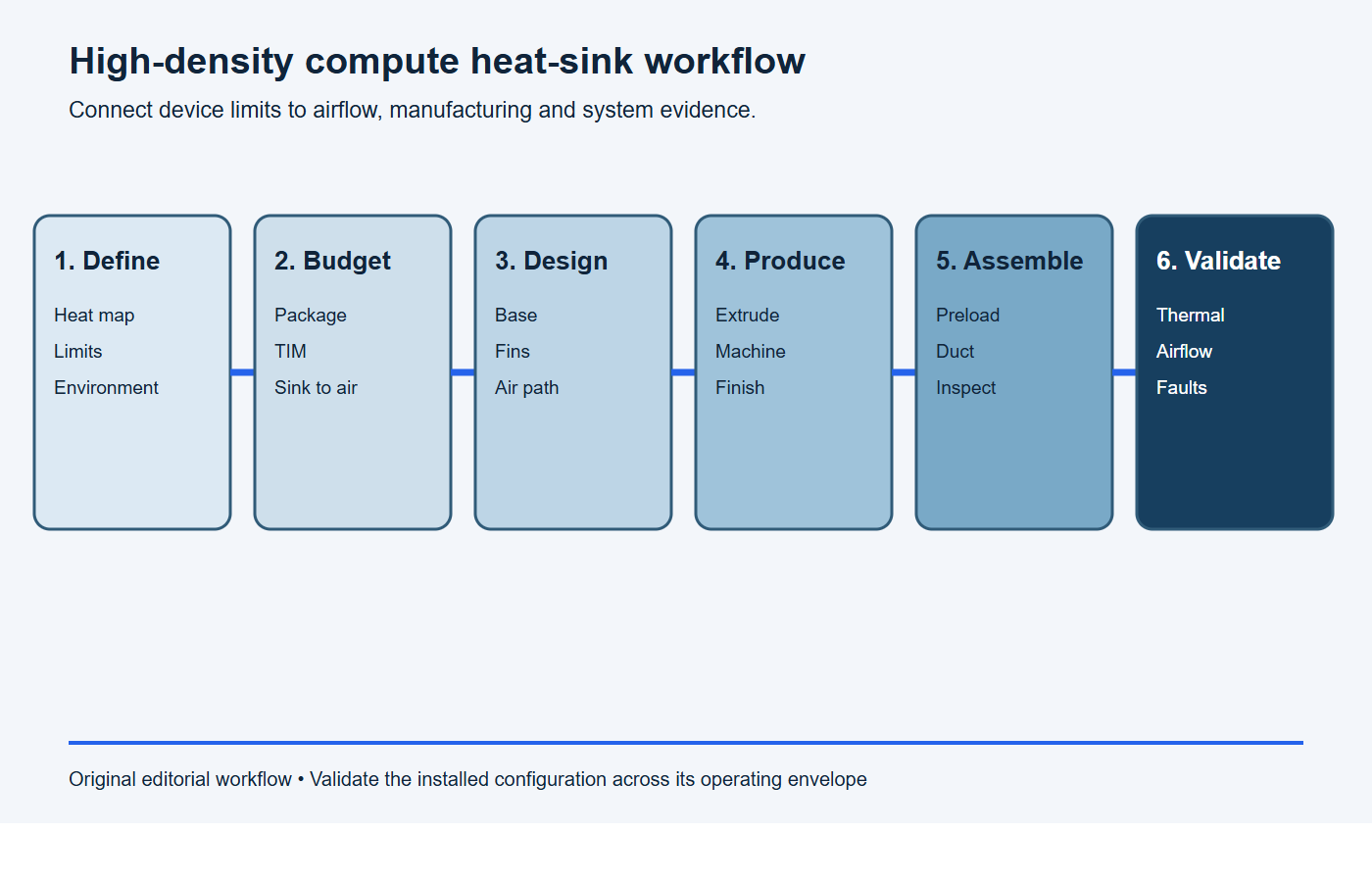
Use this production heat-sink workflow
- Define: heat map, temperature limit, inlet air, fan operating range and mechanical envelope.
- Budget: contact, spreading and convection resistance plus airflow pressure drop.
- Design: base, fins, ducting, mounting, keep-outs and service access as one system.
- Manufacture: control product form, alloy, joining, machining, finish and fin protection.
- Measure: inspect the contact interface and test thermal and airflow performance on the same configuration.
- Release: qualify representative hardware and preserve production and change-control evidence.
RFQ checklist for a production-ready heat sink
Paste this scope into the RFQ and attach the controlled drawing, device mechanical data, heat map and chassis airflow information.
RFQ scope: Please quote [heat-sink part number and revision] for [prototype quantity] and [annual volume]. The device dissipates [power profile and heat map] with a maximum [case/junction temperature]. Local inlet air is [range], available pressure is [range], and the mechanical envelope and airflow direction are [definition]. Quote the proposed aluminum alloy, product form, fin process, machining, finish, tooling, unit price, lead time and capacity. List every assumption and deviation.
Required evidence: Provide material traceability, base flatness and contact-zone inspection, fin and machined-feature results, joining and finish records, thermal/airflow test support, cleaning, packaging and fin-protection controls, first-article documentation and change-notification triggers. Identify chassis- and system-level validation outside the supplier scope.
- 3D model and controlled 2D drawing with revision and units.
- Heat-source footprint, heat map, power profile and allowable temperatures.
- Local inlet-air range, flow direction, available pressure and system impedance data.
- Maximum envelope, keep-outs, duct interface and service access.
- Alloy, temper, product form, finish and masked areas.
- TIM, contact zone, flatness, roughness if functional, preload and retention scheme.
- Critical datums, machined features and inspection method.
- Prototype and production quantities plus expected design-change stage.
- Thermal, airflow, mechanical and environmental qualification plan.
- Cleaning, fin-protection, packaging and traceability requirements.
Stop conditions: the heat sink is not ready for release
Pause tooling or production release if any condition below remains unresolved.
- the spatial heat map, transient power or allowable device temperature is missing;
- the airflow input is stated only as CFM without local pressure, fan curve, ducting and bypass context;
- the thermal-resistance budget omits TIM, contact pressure or base spreading;
- fin pitch and height cannot be manufactured, cleaned or protected reliably at the required volume;
- contact flatness, texture, preload or inspection condition is undefined;
- surface finish is selected from appearance alone without checking thermal, electrical and dimensional effects;
- simulation assumptions have not been correlated with representative hardware;
- qualification omits the intended server chassis, upstream heating or full system power state.
Frequently asked questions
Is 6063 or 6061 better for a server heat sink?
6063 is often a useful extrusion candidate, while 6061 is common for machined or more structurally demanding parts. The correct choice depends on product form, temper, geometry, joining, finish and verified system performance. Alloy conductivity alone cannot select the finished solution.
Do more fins always lower processor temperature?
No. Additional fins increase area but usually increase pressure drop and may promote bypass. Optimize fin pitch, thickness and height against the actual fan curve, ducting and heat-spreading behavior, then validate the installed assembly.
Does black anodizing make a forced-air heat sink cooler?
It can change radiative properties, corrosion behavior and appearance, but its effect on total temperature depends on the balance between radiation, convection and contact resistance. Compare finishes in a representative system if the thermal difference matters.
When should a design move from an air heat sink to liquid cooling?
Consider a liquid architecture when the required junction-to-ambient budget cannot be met within the available air temperature, pressure, acoustic, power and space limits with acceptable reliability margin. Make that decision through system analysis and prototype evidence rather than a universal power threshold.
Request an aluminum heat-sink manufacturing review
BAOSONG supports engineering review for aluminum extrusion, CNC machining and finishing. Send the controlled drawing, thermal and airflow boundary conditions, mounting stack, finish, inspection requirements and quantities through the contact page. The review can then focus on a manufacturable blank, critical machining datums, finish sequence and evidence needed for your application.
Recommended Downloads for Aluminum Alloy Selection
Use these BAOSONG references to compare alloy families, temper conditions, machinability, strength, corrosion resistance and design implications before quotation.
- Aluminum Alloy Comparison Chart (editable Excel)
- Tolerance Reference Guide (PDF)
- Aluminum CNC Machining Design Guide (PDF)
- Aluminum Part Design Checklist (editable Excel)
Need help choosing an alloy or temper for your application? Contact BAOSONG Precision.
