
Quick answer: what determines the thermal performance of an aluminum cold plate for an AI server?
Thermal performance depends on the complete path from the processor package through the thermal interface material, cold-plate base, internal channels and coolant to the server loop. Begin with a spatial heat-load map, allowable device temperatures, coolant inlet condition, flow range, pressure-drop budget, fluid chemistry, mounting load and reliability target. A material conductivity value or a single “watts cooled” claim cannot define the result.
Place channel area and turbulence where heat flux requires them while distributing flow evenly and limiting pump demand. Control base thickness, interface flatness, surface texture, TIM compression, cover-joint integrity, ports and mounting hardware together. Evaluate adjacent memory, voltage-regulation and networking components that may remain air-cooled.
Aluminum can reduce mass and support CNC-machined, extruded, brazed or welded constructions, but coolant compatibility, galvanic couples, joining process and cleanliness must be qualified. Test production-equivalent assemblies for thermal resistance, flow distribution, pressure drop, leakage, proof pressure, thermal cycling, corrosion and service handling within the specified system boundary.
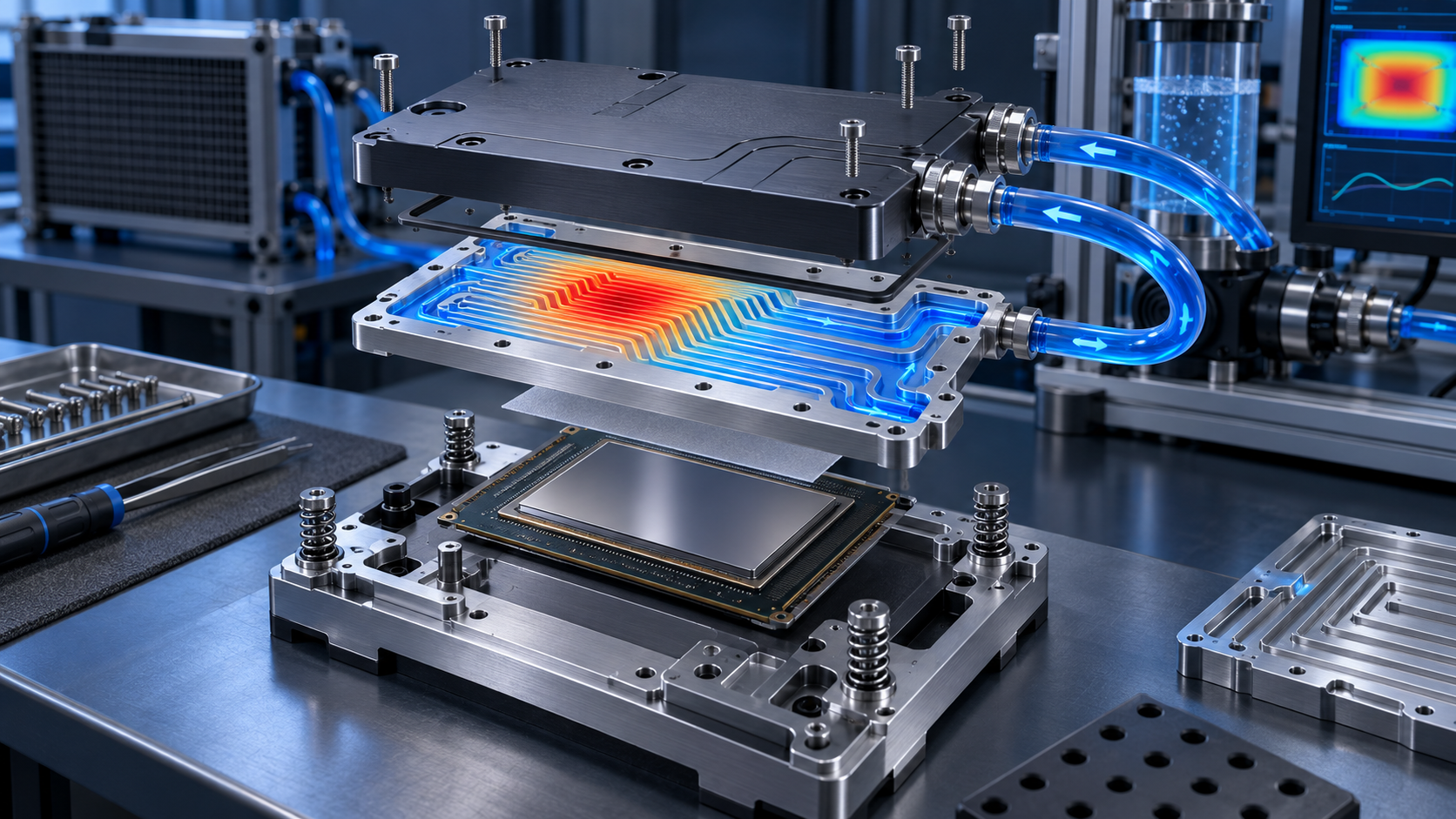
Define the liquid-cooling architecture first
Use this sequence before drawing microchannels:
- Freeze the platform inputs. Record the device heat map, allowable temperatures, coolant, flow range, inlet temperature, pump curve, pressure limits and service life.
- Build linked budgets. Allocate thermal resistance from package to coolant and pressure drop across the cold plate, hoses, manifolds and rack loop.
- Select the architecture and process together. Compare channel and manifold layouts with machining, extrusion, brazing, welding and cover-joint options.
- Control every interface. Define TIM, flatness, preload, ports, wetted materials, cleanliness, corrosion and the pressure boundary.
- Correlate analysis with production hardware. Measure temperatures, flow distribution, pressure drop, leakage, proof strength and life in the actual system configuration.
A direct-to-chip cold plate removes heat from selected server components while coolant circulates inside information technology equipment. The server loop may connect through hoses and quick disconnects to a rack manifold and coolant distribution unit, which then rejects heat to a facility loop. Hybrid servers still use air for components outside the liquid circuit.
Draw the boundaries before assigning specifications. Separate the chip package and TIM, cold plate, server hoses and manifold, rack distribution, CDU heat exchanger and facility water. State which supplier owns flow balance, water quality, controls, leak detection and thermal acceptance at each interface.
Berkeley Lab’s direct-liquid-cooling study describes moving heat away from electronics through a liquid loop near the source. ASHRAE’s data-center handbook chapter explains common facility-water, CDU and liquid-cooled IT equipment arrangements. Apply the requirements chosen for the actual platform rather than treating either source as a universal cold-plate drawing.
Build an input matrix before designing channels
| Input | Required definition | Cold-plate consequence | Validation evidence |
|---|---|---|---|
| Heat source | Power map, hotspot location, transient profile and device limits | Base thickness, channel density, coverage and mounting | Mapped temperatures at specified workload |
| Coolant | Composition, concentration, additives, quality and life limits | Material, joining, seals, corrosion and cleanliness | Compatibility and fluid-control records |
| Hydraulics | Inlet pressure, flow range, pressure-drop allocation and flow direction | Channel size, manifolds, ports and parallel-path balance | Flow-versus-pressure-drop curve |
| Mechanical stack | Package height, TIM, keep-outs, board support and fastening | Interface plane, compliance, preload and deflection | Assembly load and contact verification |
| Environment | Inlet temperature, dew point, altitude, shipping and service conditions | Condensation control, material and cycle requirements | Environmental and thermal-cycle results |
| Reliability | Operating life, cycles, allowable leakage and fault response | Joint architecture, proof margin, monitoring and traceability | Leak, pressure, cycle and change-control data |
Freeze the coordinate system used for the heat map and package definition. A cold plate can be thermally optimized against the wrong hotspot position when the processor, substrate and board drawings use different origins or orientations.
Create a thermal-resistance budget
Divide the path into package-to-TIM contact, conduction through the TIM, cold-plate contact, base conduction, convection into the coolant and coolant temperature rise. Include spreading resistance where the channel field does not align with the heat source. The total device temperature also depends on the inlet coolant temperature.
Assign a target and uncertainty to each major term. TIM thickness and conductivity, contact pressure, base flatness, channel geometry, flow rate and fluid properties all vary. Use sensitivity analysis to identify the variables that need tighter production control.
Report thermal resistance with the heat input, inlet temperature, flow, coolant, sensor method, mounting state and calculation points. Values from different rigs or reference temperatures are not directly comparable without this context.
Map hotspots instead of using average package power
AI accelerators can contain compute regions, memory stacks and interconnect areas with unequal heat flux. Obtain the platform’s approved power map, mechanical keep-outs and allowable contact zones. If only a total power value is available, document the assumptions and test sensitivity to hotspot location.
Increase local heat-transfer capability where the mapped heat flux demands it. Options include narrower or denser channels, pins, fins, impingement features or a thinner conduction path. Each can increase pressure drop, manufacturing difficulty, fouling sensitivity or structural stress.
Do not extend an aggressive channel field under fragile or low-load package regions without checking mechanical support. Thermal and mechanical teams should review the cold plate and package stack together.
Balance base thickness, spreading and pressure integrity
A thinner base shortens the conduction path but can increase deflection and stress over channels. A thicker base improves stiffness and heat spreading but adds conduction resistance, mass and material. The useful thickness follows local heat flux, channel roof/floor geometry, pressure, mounting span and allowable interface deformation.
Analyze the cold plate under operating pressure, proof pressure and mounting preload. Include the cover joint, port loads and fastener reactions. Deflection can change TIM thickness and local contact even when stress remains below the material allowable.
Validate the final joined construction. Brazing, welding or other bonding can change flatness and material condition, so a pre-join base measurement does not prove the finished interface.
Design channels as a thermal and hydraulic network
Channel width, depth, length, surface area, roughness and turning losses affect heat transfer and pressure drop. Small passages can improve local convection but raise flow resistance and contamination sensitivity. Large passages reduce resistance but may create weak velocity or poor hotspot coverage.
Use computational fluid dynamics or an appropriate reduced model to compare pressure, velocity, temperature and flow distribution. Verify mesh independence, boundary conditions and fluid properties across the intended temperature range. Correlate predictions with instrumented hardware.
Review stagnation zones, sharp expansions, recirculation, trapped gas and regions that cannot drain. A visually symmetric pattern does not guarantee even distribution when port location and header pressure vary.
Design inlet and outlet manifolds for flow uniformity
The headers must distribute coolant to parallel channels without sending most flow through the nearest path. Adjust header taper, channel entrances, restrictions or flow arrangement based on the network model. Include manufacturing variation in the flow-balance study.
Parallel cold plates at server or rack level interact. A low-resistance plate may take excess flow while another is starved unless the manifold, controls or calibrated restrictions balance the circuit. Cold-plate pressure drop should fit the server and CDU pump budget rather than being optimized in isolation.
Berkeley Lab’s liquid-cooling requirements white paper highlights the need to coordinate equipment and facility interfaces. Use the adopted platform requirements to align component measurements with system monitoring.
Choose coolant and water quality before material qualification
Specify the exact heat-transfer fluid, concentration range, additive package, allowable contaminants, conductivity or other quality limits, temperature and maintenance interval. “Water-glycol” is not a complete material specification. Fluid formulation can affect heat capacity, viscosity, pressure drop, seal compatibility and corrosion.
Control make-up fluid, cleaning residues, biological growth and particles through the system owner’s program. Aluminum corrosion behavior depends on alloy, surface condition, pH, inhibitors, temperature, dissolved species, flow and contact with other metals.
Qualification should expose production-representative coupons and joined assemblies to the approved fluid and mixed-material loop. Check mass loss or gain, visual attack, deposits, blocked passages, seal behavior and changes in thermal/hydraulic performance according to the program.
Manage galvanic couples in mixed-metal loops
An aluminum cold plate may share coolant with copper, brass, stainless steel, nickel-plated parts and other materials. Galvanic behavior requires an electrical path and electrolyte and is influenced by exposed area ratios and fluid chemistry. Coatings alone should not be assumed to isolate every internal surface for life.
Map wetted materials, plating, fasteners, ports, brazing filler, sensors and quick disconnects. Define which couples are allowed, which require isolation and how the fluid inhibitor program supports them. Include coating holidays, cut edges and service damage in the assessment.
Use the same material and fluid stack in corrosion and life testing. A coupon of bare aluminum in fresh fluid cannot represent a complex server loop after aging and maintenance.
Decide whether aluminum is the right cold-plate material
Aluminum offers low density, good machinability and useful thermal conductivity, and it can support several near-net manufacturing routes. Copper offers higher bulk thermal conductivity but adds mass, cost and different joining and compatibility constraints. The best choice depends on the system rather than a single property.
Compare predicted device temperature, pressure drop, mass, stiffness, corrosion controls, joining yield, cleanliness, supply chain and total production cost. A well-designed aluminum channel field can outperform a poorly integrated copper plate in a specific system, but aluminum should not be selected where the required thermal or fluid-compatibility margin cannot be demonstrated.
Review BAOSONG’s aluminum alloys for heat sinks and enclosures and CNC alloy selection guide, then qualify the exact product form, temper and joint process.
Select a manufacturable cold-plate architecture
| Architecture | Useful starting point | Strengths | Key risks |
|---|---|---|---|
| Machined base plus sealed cover | Prototype and moderate-volume complex channels | Fast design iteration and precise hotspot geometry | Cycle time, cover joint, distortion and trapped debris |
| Extruded channel body plus closures | Repeated straight passages and scalable lengths | Reduced machining and consistent channel section | Constant geometry, end-manifold design and closure integrity |
| Brazed multi-piece plate | Dense passages and distributed heat-transfer area | Integrated internal structures and thin assemblies | Filler flow, cleanliness, material condition, voids and flatness |
| Friction-stir or fusion-welded cover | Machined channels with permanent metallic closure | No service gasket in the main channel field | Heat/distortion, weld path, termination and leak inspection |
| Additively manufactured plate | Geometry unavailable by conventional cutting | Complex internal distribution and part consolidation | Powder removal, surface state, qualification and cost |
Choose from expected quantity, revision rate, passage scale, pressure, material compatibility, flatness and inspection access. BAOSONG’s guide to extrusion plus CNC machining explains when a near-net channel body can reduce cutting.
Design the chip interface, TIM and mounting preload together
Define the package contact region, keep-outs, allowable load, mounting points and board support. The TIM must fill surface variation at a controlled thickness without creating excessive pump-out, dry zones or assembly force. Use supplier data within the qualified pressure and temperature range.
Flatness and surface texture should support contact without becoming tighter than the assembly can use. A highly polished plate may still perform poorly if it bows under spring load. Specify the interface in the final joined and finished state with a defined support condition.
Spring screws or compliant mounts can distribute preload across package-height and tolerance variation. Verify fastener sequence, stop height, spring range and board deflection. Measure contact or use pressure film/qualified methods during development where appropriate.
Control ports, hoses and quick-disconnect loads
Port threads, glands, tubes and quick disconnects apply assembly and service loads to the plate. Provide wrench access and reaction features so technicians do not twist a thin cover or disturb the chip interface. Define insertion, removal and hose-bend forces.
Keep port bosses away from weak channel roofs and provide enough material for the sealing method. Identify the seal, surface, torque and inspection. Prevent sealant or thread debris from entering small passages.
Design for drainage, filling and air removal in the installed server orientation. High points can trap gas and reduce wetted area. Service procedures should control caps, contamination and spill response.
Engineer the cover joint as a pressure boundary
Possible closures include brazing, friction-stir welding, laser or other qualified welding, diffusion-based processes, soldering in compatible systems, adhesive bonding and gasketed fasteners. Each creates a different temperature cycle, material condition, leak path and inspection strategy.
Provide continuous lands, avoid abrupt channel-to-joint transitions and keep the joint away from severe local stress where possible. Model cover deflection and joint loading at operating and proof conditions. Consider thermal expansion between the cold plate and board or carrier.
Define acceptable internal and external joint indications, rework limits and final flatness. Process qualification should connect representative joint coupons to production parameters and full cold-plate tests.
Plan CNC machining around channel integrity
Use practical cutter diameters, corner radii, channel depths and tool reach. Deep narrow channels increase deflection, breakage and chip evacuation risk. Keep sufficient floor and wall thickness for pressure and post-join machining variation.
Establish stable datums early, rough material symmetrically where needed and finish the chip interface after processes likely to move it. Protect sealing lands and small channel edges during deburring. Inspect remaining wall where tool or stock variation can threaten the pressure boundary.
BAOSONG’s articles on lower-cost CNC part design and practical aluminum machining tolerances support early DFM review.
Control internal cleanliness and burrs
Small particles can block channels, damage pumps or seals and contaminate connectors. Define particle size/count or another cleanliness measure based on the narrowest system passage and component requirements. A visual “clean” note is difficult to audit.
Plan chip evacuation, washing, ultrasonic or other qualified cleaning, rinsing and drying for the chosen construction. Remove burrs at channel intersections without changing the designed flow restriction. Prevent abrasive media, polishing compound and masking residue from entering the wetted path.
Cap cleaned ports and package the plate in a controlled environment. Set hold-time and re-clean rules if storage or handling can compromise cleanliness.
Use surface finishes only where they serve a defined purpose
External anodizing or conversion treatment may support corrosion, handling or appearance, but internal coating requires demonstrated compatibility, coverage and durability. Mask or control chip-contact faces, sealing lands, ports, electrical contacts and joined regions according to the process plan.
A finish can change dimensions and thermal contact. State whether flatness, texture and port limits apply before or after finishing. Do not leave rack marks or masking transitions on the chip interface or primary seal.
Coordinate requirements through BAOSONG’s aluminum surface-finishing and anodizing resources before the drawing is released.
Test thermal and hydraulic performance on the same configuration
Measure flow, inlet/outlet pressure, inlet/outlet coolant temperature, heat input and relevant device or simulator temperatures. Define sensor locations, calibration, insulation, ambient air and stabilization. Create a flow-versus-pressure-drop curve across the operating range.
Use a heater or thermal test vehicle with a spatial heat map representative of the target device. A uniform heater may hide a hotspot-distribution problem. Document TIM, preload, plate orientation and any bypass heat path.
Calculate energy balance and investigate unexplained heat loss. Repeat tests across units and manufacturing lots to distinguish design behavior from specimen variation.
Qualify pressure, leakage and life separately
| Test | Purpose | Conditions to define | Evidence |
|---|---|---|---|
| Leak test | Detect through-paths across the pressure boundary | Medium, sensitivity, pressure, time, temperature and allowable rate | Calibrated result and tested boundary |
| Proof pressure | Demonstrate integrity above operating condition | Level, ramp, hold, restraint and permanent-deformation rule | Pressure record and post-test inspection |
| Burst characterization | Understand ultimate failure mode where required | Fluid, ramp, guards, sample plan and failure definition | Failure pressure/location and lot traceability |
| Thermal cycle | Expose joint, seal and flatness fatigue | Fluid/ambient temperatures, ramps, dwells, pressure and cycles | Intermediate/final leak and dimensional data |
| Corrosion compatibility | Evaluate fluid and mixed-material interaction | Production materials, aged fluid, temperature, flow and duration | Material, deposit, leak and performance changes |
| Flow endurance | Assess erosion, fouling and pressure-drop drift | Fluid quality, velocity, temperature, contamination and hours | Before/after hydraulic and cleanliness results |
Do not use one test to claim another property. A leak test does not establish burst margin; a hydrostatic proof test does not prove thermal resistance; a short thermal test does not prove corrosion life.
Prevent condensation and plan leak response
If coolant surfaces fall below the surrounding air’s dew point, condensation can form outside a leak-free cold plate. Define server inlet humidity, coolant temperature and transient states. Use control limits, insulation, drainage or other system measures as the platform requires.
Include leak detection, shutoff, alarms and service procedures at server and rack level. OCP’s cold-plate materials emphasize spill management, detection response and serviceability as parts of deployment, not only cold-plate heat transfer.
Locate potential leakage away from energized or sensitive components where practical, and provide a predictable path for detection. Validate connectors and hoses in the installed routing and after service cycles.
Match dimensions to capable measurement
Use CMM or appropriate gauges for port and mounting relationships, form/optical methods for interface flatness, texture instruments for specified surface parameters, and calibrated flow/pressure/temperature sensors for performance. CT or sectioning may support internal-feature development where conventional access is limited.
Define support and restraint during flatness measurement. A thin plate can change shape when mounted. Record reference temperature and final finish/joined state. The acceptance method should resolve the tolerance with suitable uncertainty. ASME Y14.5-2018 (R2024) supplies the GD&T language for stating datum-related interface, port and mounting requirements on engineering drawings.
NIST’s paper on uncertainty and dimensional calibrations explains that every measurement is an estimate with uncertainty. Apply an uncertainty budget and decision rule appropriate to each dimensional and test result.
Use this AI-server cold-plate workflow
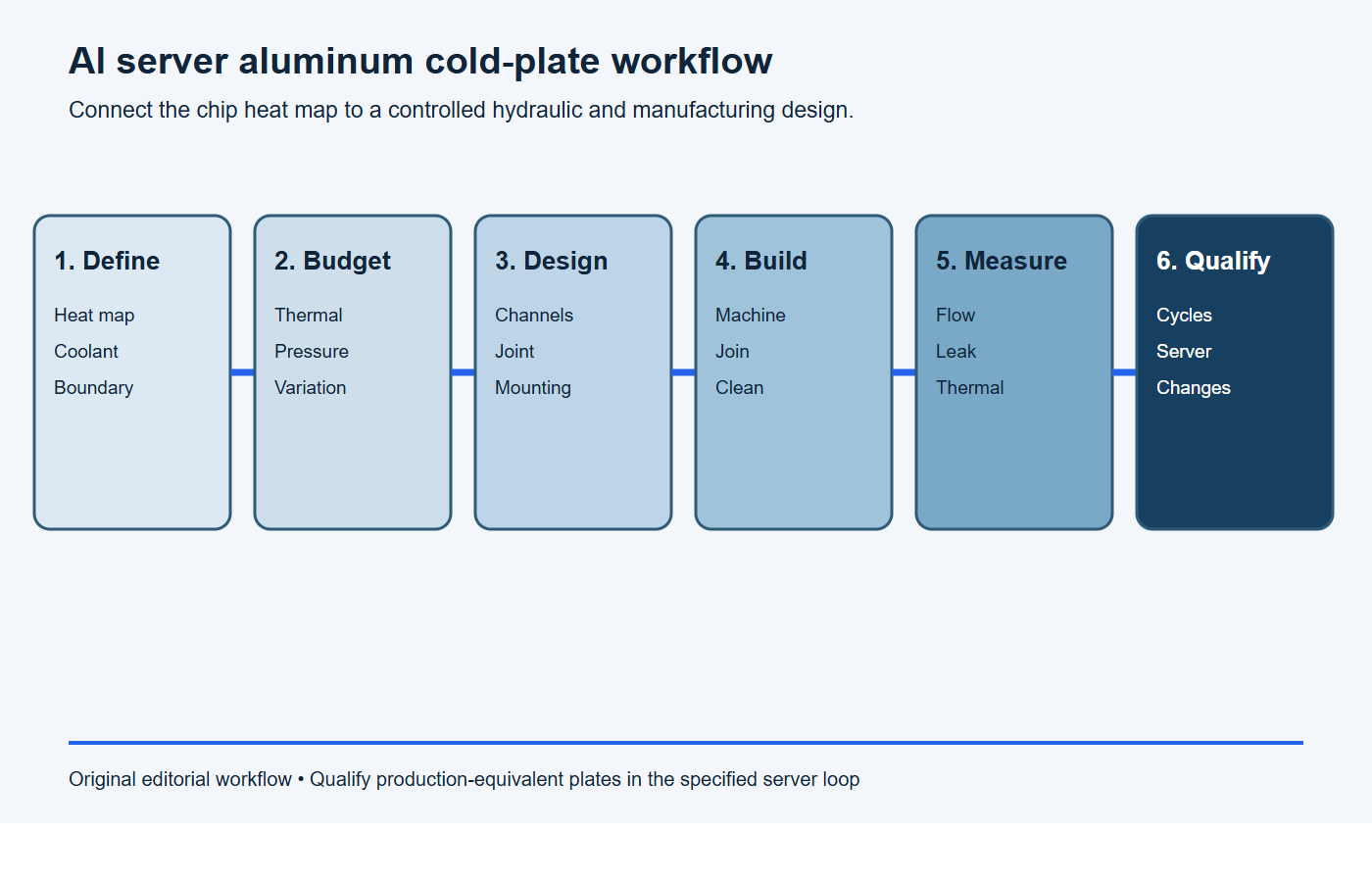
- Define: heat map, temperature limits, coolant, flow, pressure and system boundary.
- Budget: thermal resistance, pressure drop, contact and manufacturing variation.
- Design: base, channels, manifolds, ports, joint, mounting and service features.
- Manufacture: control alloy, machining, joining, finishing, cleaning and traceability.
- Measure: geometry, flatness, cleanliness, leak, pressure, flow and thermal response.
- Qualify: production-equivalent plates in the server loop and life environment.
What should a cold-plate RFQ include?
Paste this scope into the RFQ and attach the controlled cold-plate drawing, device mechanical data, heat map and rack-loop requirements.
RFQ scope: Please quote [cold-plate part number and revision] for [prototype quantity] and [annual volume]. Inputs are [device heat map], [maximum temperatures], [TIM and preload], [coolant specification], [inlet-temperature and flow range], [pressure-drop limit], [operating/proof pressure] and [service life]. Quote the proposed aluminum alloy, architecture, manufacturing and joining route, tooling, unit price, lead time and capacity. List all assumptions and deviations.
Required evidence: Provide material and wetted-process traceability, dimensional and flatness results, cleanliness data, flow/pressure-drop and thermal results, leak-test method and sensitivity, proof or cycle evidence, first-article documentation, port protection and change-control triggers. Identify server- and rack-level validation outside the supplier scope.
- Controlled 3D model, 2D drawing and coordinate definition
- Device mechanical drawing, heat-flux map and allowable temperatures
- TIM material, target thickness, preload and mounting hardware
- Coolant specification, quality limits and wetted-material restrictions
- Flow range, pressure-drop budget, operating pressure and temperatures
- Proof, burst, leak, thermal-cycle and corrosion requirements
- Alloy, temper, manufacturing and joining constraints
- Critical dimensions, final-state flatness, texture and inspection method
- Cleanliness, port capping, packaging and traceability requirements
- Prototype, qualification and annual quantities with revision plan
Stop conditions: the cold plate is not ready for release
Pause tooling or production release if any condition below remains unresolved.
- the spatial heat map or allowable device temperatures are missing;
- flow and pressure-drop requirements do not include the real pump and parallel-loop behavior;
- TIM type, thickness, preload, contact region or final flatness condition is undefined;
- coolant chemistry, quality limits or mixed-metal compatibility has not been approved;
- minimum wall, cover joint, ports or cross-drill closures lack pressure-boundary controls;
- leak rate, test medium, pressure, temperature, stabilization or sensitivity is unspecified;
- internal burrs, particles, flushing, drying and port capping have no acceptance plan;
- CFD or prototype data is being used to release a different production construction without correlation.
Share the platform thermal and hydraulic boundary before freezing internal geometry. BAOSONG can review machined and near-net aluminum cold-plate components for channel manufacturability, joint lands, flatness, ports, finishing and inspection against the supplied specification. Use the contact page to request a drawing-based review.
Frequently asked questions
Is aluminum suitable for AI-server cold plates?
It can be when thermal performance, coolant chemistry, mixed-metal compatibility, joining, pressure integrity and life are demonstrated. The system may still favor copper or another construction for a particular platform.
What is the best channel size for an AI cold plate?
There is no universal size. It follows the hotspot map, coolant properties, flow and pressure budget, manufacturing capability, cleanliness and reliability requirements.
Does lower pressure drop always mean a better cold plate?
No. Very low resistance may reduce local velocity or take excess flow in a parallel network. Optimize device temperature and system pumping within the complete server/rack flow balance.
How should cold-plate flatness be specified?
Define the contact region, final joined and finished state, support or mounting condition, reference temperature, measurement method and limit derived from the TIM and package load analysis.
Can anodizing be used inside the coolant channels?
Only with a qualified process and fluid system. Coverage, defects, dimensional change, thermal resistance, compatibility and life must be demonstrated on representative joined plates.
Which tests are required before production?
A typical project separates dimensional, cleanliness, flow/pressure-drop, thermal, leak, proof, cycle and compatibility evidence. The exact levels and sample plans must come from the platform reliability specification.
Recommended Downloads for Aluminum Alloy Selection
Use these BAOSONG references to compare alloy families, temper conditions, machinability, strength, corrosion resistance and design implications before quotation.
- Aluminum Alloy Comparison Chart (editable Excel)
- Tolerance Reference Guide (PDF)
- Aluminum CNC Machining Design Guide (PDF)
- Aluminum Part Design Checklist (editable Excel)
Need help choosing an alloy or temper for your application? Contact BAOSONG Precision.
