
Quick answer: how can you reduce the cost of CNC machined aluminum parts?
Reduce the work needed to make and verify the part while preserving its function. The largest opportunities usually come from selecting a sensible starting form, removing fewer cubic centimeters of aluminum, reducing setups, allowing practical tool access, assigning tight tolerances only to functional features and simplifying finishing and inspection.
Unit cost is not controlled by material price alone. Programming, fixtures, setup time, tool changes, cutting time, tool wear, deburring, finishing, inspection, scrap risk and documentation all contribute. A small design change that lets a rigid standard tool reach the feature can matter more than a small change in raw aluminum price.
The right question is not “How do I make every feature cheaper?” It is “Which features create product value, and what is the least complex process that produces and verifies them reliably at the required quantity?” Do not relax a safety-, fit- or sealing-critical requirement without engineering approval.
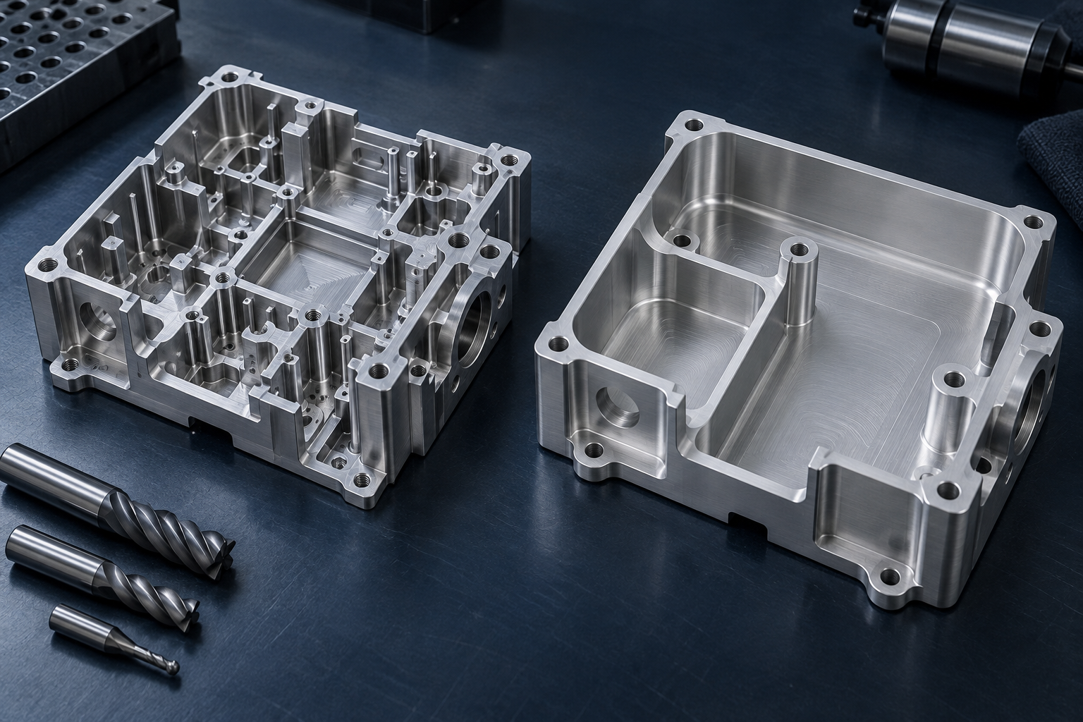
Seven-step CNC aluminum cost-reduction process
| Step | Review | Required output |
|---|---|---|
| 1 | Map cost to stock, cutting, setups, inspection and finish | Cost-driver list tied to function |
| 2 | Choose the lowest-work starting form | Plate, bar, extrusion or near-net route comparison |
| 3 | Reduce removal and improve cutter access | Revised pockets, radii and material distribution |
| 4 | Reduce setups and accidental tool variety | Datum, clamp and standard-tool plan |
| 5 | Control thin walls and tolerance scope | Functional tolerance and released-state plan |
| 6 | Simplify finish and inspection | Cosmetic zones, masking and risk-based reports |
| 7 | Quote the forecast quantity and validate changes | Comparable total-cost model and release checklist |
Step 1: build a cost-driver map
| Cost driver | What creates the work | Design response | What must stay protected |
|---|---|---|---|
| Starting stock | Large billet, low material yield or unsuitable product form. | Compare plate, bar, extrusion, near-net blank or another process. | Alloy, temper, properties, traceability and design-change flexibility. |
| Machine time | High removal volume, deep features, small tools and repeated finishing passes. | Open cavities, increase radii, reduce unnecessary pockets and use standard tools. | Mass, stiffness, flow, thermal and assembly functions. |
| Setups and fixtures | Features on many sides, unstable locating surfaces or difficult clamping. | Align features, create stable datums and combine accessible operations. | Feature relationships and free-state part condition. |
| Inspection | Tight blanket tolerances, difficult access and extensive reports. | Control critical features individually and agree risk-based reporting. | Fit, alignment, sealing, safety and contractual evidence. |
| Finishing | Masking, cosmetic handling, multiple finishes or post-finish rework. | Define functional and cosmetic zones and choose a coherent process sequence. | Corrosion, wear, electrical contact and appearance requirements. |
This map separates real design value from manufacturing work that the customer may not need. It also prevents a common mistake: reducing machining price while creating more assembly, quality or lifecycle cost somewhere else.
Step 2: choose the starting material form
A part cut from rectangular plate offers flexibility and avoids dedicated profile tooling, but a thin frame with a constant cross-section may waste substantial material and spindle time. Bar can suit turned or compact prismatic components. Extrusion can provide a near-net continuous cross-section. Forging, casting or sheet fabrication may become relevant when geometry and volume justify their tooling and qualification.
Compare total route cost, not only raw-stock price. Include minimum order, die or tooling, lead time, machining allowance, inspection, finishing, inventory and the risk that the design will change. Begin with the complete precision CNC machining requirement, then compare it with near-net alternatives. For long constant sections, see when extrusion can replace machining from solid billet.
Material grade must still meet function. A lower-cost alloy that needs a larger section, more finishing or a difficult supply condition may not lower finished-part cost. Use the aluminum alloy selection guide to compare strength, corrosion, finishing and stock form before asking for a substitution.
Step 3: reduce removal and improve cutter access
Large pockets can reduce weight, but every removed volume needs a toolpath, chip evacuation and time. If the pocket contributes little to mass, stiffness, thermal behavior or clearance, leaving material in place may be cheaper. A shallow relief around an interface may achieve the same function as hollowing the complete part. Protolabs’ guide to common machined-part design mistakes likewise recommends revisiting pockets that exist only to remove weight; its service rules remain specific to that supplier.
Keep enough material for rigidity during machining. An aggressively lightened design can require staged roughing, extra support, low-force finishing and more inspection because thin floors and walls move. Review the finished mass saving against longer cycle time and higher process risk.
When weight is critical, use load paths and structural analysis to decide where material can remain. Do not distribute many small pockets only to create a “machined” appearance. Simple ribs, open windows or a near-net starting form can provide a better balance.
Use generous internal radii and accessible pockets
A rotating end mill leaves an internal radius. A small corner radius can force a smaller cutter; a deep pocket then requires that small tool to reach farther. Tool compliance, corner engagement, chip recutting and cycle time can all increase. Protolabs’ cost-reduction design guidance illustrates the same link between corner relief, cutter size and machining time. Its numeric service limits are supplier-specific and are not BAOSONG capability values.
Allow the largest radius the assembly permits. If a square mating component must enter the pocket, consider a local dog-bone or T-bone relief, or round the mating component. Open one side of a pocket where product function allows. Keep floor radii and vertical corner radii distinct on the drawing. Xometry’s internal-corner design discussion also explains why giving the cutter room to turn can reduce corner slowdown and vibration; its numeric recommendations are not universal limits.
Avoid deep, narrow cavities that require long-reach tools when the same function can be achieved by a shallower feature, side access, a cover plate or a split assembly. Review tool access, cutter stiffness and workpiece support as part of the aluminum CNC milling plan.
Step 4: reduce setups and tool variety
Every new setup requires handling, locating, clamping, coordinate establishment and verification. Features on six sides do not automatically require six setups, but opposing undercuts, inaccessible holes or unstable datum transfers can force extra work.
Group related features so they can be reached from compatible directions. Put critical bores, mounting holes and faces into a datum scheme that a fixture can reproduce. Add suitable clamp areas and avoid placing every external surface under a cosmetic restriction. A deliberate fixturing tab or sacrificial boss may cost less than a complex custom fixture, provided the removal and final condition are specified.
Multi-axis equipment can reach several faces and reduce reclamping for suitable parts. It does not make all geometry cheaper: programming, tooling, collision clearance, machine availability and inspection still matter. Compare a simple three-axis route with indexed or simultaneous multi-axis aluminum machining for the actual quantity and feature relationships.
Prefer standard tools and repeatable features
Standard drills, end mills, thread forms and inspection tools reduce special-tool sourcing and simplify replacement. A family of repeated hole diameters and radii may need fewer tool changes than many nearly identical sizes. Reuse a proven thread size where the assembly permits rather than adding a unique tap for one noncritical hole.
This does not mean forcing every feature to one dimension. Bearing fits, sealing lands and connectors have functional standards. The cost-saving task is to remove accidental variety: decorative radii that require separate cutters, shallow counterbores with unique sizes, unnecessary 3D contours or engraved text that could be laser marked.
Specify edge breaks by functional need. A broad “break all edges” note can create uncertainty on sealing, mating and cosmetic boundaries. Identify edges that must be safe to handle, edges that must remain controlled and inaccessible intersections where automated deburring may not reach.
Step 5: control thin walls and tolerance scope
Wall thickness is only one part of rigidity. Unsupported height and length, ribs, floor connection, material condition, clamp position and cutter force all influence deflection. A tall free wall can move during cutting and spring back after release, while a short wall supported on three sides may be far more stable at the same thickness.
Increase thickness or shorten the free span where possible. Add ribs around functional interfaces, use gradual transitions and preserve support until late in the machining sequence. If the thin wall is required for mass or thermal reasons, identify it as a critical process feature and accept the necessary planning and inspection rather than applying the same low-cost expectation as a rigid block.
Assign tight tolerances only where function needs them
Blanket tight tolerances increase process control and inspection even on dimensions that only provide clearance. Start from the assembly: which feature locates the part, which surface seals, which bore carries a bearing, and which hole pattern permits fastener assembly? Give those relationships explicit controls and use an appropriate general tolerance for the rest.
ASME’s official Y14.5-2018 (R2024) overview describes the common symbols, rules and definitions for dimensional and geometric tolerancing. Use the governing standard and edition required by the project. A clear datum system can communicate functional relationships more directly than a chain of coordinate dimensions with unnecessarily small limits.
Do not relax tolerances by email while leaving the drawing unchanged. Update the controlled product definition and revision. For feature-level planning, see Aluminum CNC Machining Tolerances: What Is Practical?
Step 6: simplify finishing and inspection
Fine surface texture can require smaller steps, slower feeds, additional passes, dedicated tools or polishing. Apply it to the sealing, sliding, optical or contact surfaces that need it. A hidden clearance pocket usually does not need the same texture as a gasket land.
Distinguish dimensional tolerance, geometric tolerance, surface texture and cosmetic appearance. They are separate requirements and may require different methods. Do not use a generic “smooth finish” note as a substitute for a measurable functional requirement or an approved visual standard.
Plan anodizing before finalizing dimensions
Finishing can add masking, racking, handling, appearance control and post-process inspection. Reduce cost by using one coherent finish where it meets the product need, defining cosmetic zones, allowing practical rack locations and identifying electrical or precision interfaces that must be masked.
State whether critical dimensions apply before or after finishing. Avoid specifying color, gloss and texture more tightly than the product requires, especially when several components must appear together. Coordinate the drawing with the surface-finishing plan and requirements for anodized aluminum parts.
Match inspection effort to feature risk
Inspection is part of delivered cost. A complete report for every dimension on every part can require more time than the machining of a simple component. Define which characteristics need first-article evidence, which need in-process control, which need lot sampling and which are verified by general workmanship.
Do not reduce inspection below the level needed for the product and contract. Safety, regulated and high-consequence interfaces may justify extensive records. The cost opportunity is to align evidence with risk and remove duplicate or ambiguous requirements.
NIST’s publication on uncertainty and dimensional calibrations explains why a measurement result is an estimate with associated uncertainty. A tolerance that is difficult to measure reliably can increase fixture, equipment and decision-rule effort even when it is straightforward to cut. Connect the drawing to the quality and inspection plan before quotation.
Step 7: optimize for quantity and design life
Prototype and production economics differ. A flexible billet route may be best while geometry is changing. Dedicated fixtures, soft jaws, extrusion tooling or another near-net process may become attractive after demand and revision stability increase. Include expected repeat orders and design maturity in the RFQ.
A low unit price can hide nonrecurring engineering, tooling, inventory or change costs. Compare total spend for the forecast quantity and likely revisions. For premium components, also consider consistency, traceability, inspection records, packaging and the cost of assembly disruption.
Use a function-to-cost review before quotation
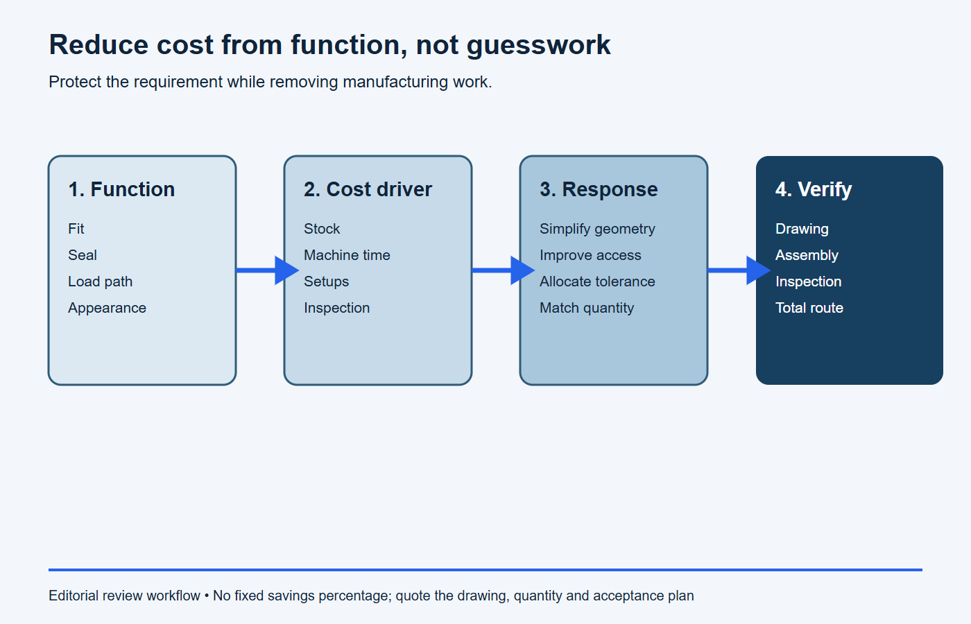
The diagram below provides a repeatable sequence: identify the function, locate the cost-generating feature, revise the design or process, then confirm that verification still protects the product.
| Functional need | Possible hidden cost | Review option | Verification to retain |
|---|---|---|---|
| Locate a circuit board | Fully sharp pocket corners and tight envelope tolerance. | Add local corner relief or round the board corners; control only locating points. | Board clearance, connector alignment and datum relationship. |
| Reduce housing mass | Deep pockets, thin floors and long roughing time. | Keep material outside the load/thermal path, open the pocket or consider extrusion. | Mass, stiffness, modal, thermal and environmental requirements. |
| Mount a bearing | Applying bearing-seat tolerance and finish to surrounding noncontact surfaces. | Control the bore and functional shoulder individually. | Fit, axis relationship, runout and surface requirement. |
| Create a premium exterior | Cosmetic requirements on clamp and hidden surfaces; multiple finish steps. | Define visible zones, grain direction, rack locations and approved appearance basis. | Customer-visible appearance, corrosion and handling durability. |
Production cost-release checklist
- Every tight feature and cosmetic requirement has a stated functional reason.
- The starting stock and alternative near-net routes were compared at the forecast quantity.
- Tool access, radii, pocket depth, thin walls, clamps and setup transfers are reviewed.
- Tolerances and surface texture are assigned only where assembly or performance needs them.
- Finishing, masking, handling and post-finish inspection are included in the route.
- Quotations use the same revision, material, quantity, inspection, packaging and delivery boundary.
- The approved first article and cost basis are protected through change control.
Stop conditions: the cost reduction is not ready
- The proposed saving removes a safety, fit, seal, load or regulatory requirement.
- A lower material price creates more machining, finishing or qualification work.
- Weight pockets cost more to cut and inspect than the verified product value they create.
- Small radii or deep cavities have no functional purpose and require special long-reach tools.
- A tolerance was widened without checking mating parts and the assembly stack.
- A finish simplification changes corrosion, grounding, wear or customer-visible appearance.
- The unit-price comparison hides tooling, minimum order, inventory, scrap or revision exposure.
Copy-ready cost-focused DFM checklist
- Revision-controlled 3D model and 2D drawing.
- Function of critical fits, seals, alignments and load paths.
- Alloy, temper, starting form and allowed substitutions.
- Expected prototype, production and repeat quantities.
- Critical dimensions, datums, surface texture and acceptance stage.
- Finish, masking, cosmetic zones and color-matching needs.
- Inspection reports, sampling and material traceability requirements.
- Assembly context and mating-part geometry where relevant.
- Target areas for cost reduction, without deleting mandatory requirements.
Use BAOSONG’s engineering-support resources to prepare the review, or send the drawing, quantity and application requirements for a manufacturability discussion. A useful review should return specific design choices and their functional tradeoffs, not a generic instruction to “make tolerances looser.”
Frequently asked questions
Does using 6061 always make a CNC aluminum part cheaper?
No. 6061 is widely available in many forms, but finished cost depends on the required stock, temper, geometry, machining route, finishing and supply conditions. Select material from function and quote the complete route.
Is a three-axis machine always cheaper than five-axis machining?
No. A simple three-axis setup can be economical, but multiple reclampings may cost more than an indexed multi-axis route for a suitable part. Compare total setup, programming, cutting and inspection effort.
Should all noncritical dimensions use wide tolerances?
They should use tolerances appropriate to manufacturing, assembly and the governing drawing standard. “Noncritical” does not mean uncontrolled. Apply individual requirements to functional features and a clearly defined general tolerance to the remainder.
Can splitting one complex part into two reduce cost?
Sometimes. Splitting can improve access and reduce deep machining, but adds fasteners, alignment, sealing, inventory and assembly variation. Compare the complete product route and service requirements.
Recommended Downloads for CNC Machining Design
Use these BAOSONG references to improve tool access, feature geometry, practical tolerances and CNC process planning before release.
- Aluminum CNC Machining Design Guide (PDF)
- CNC Milling Guide: Pockets, Walls, Corners & Tool Access (PDF)
- CNC Turning Guide: Diameters, Threads & Concentric Features (PDF)
- CNC Machining Tolerance Guide (reference sheet)
- Aluminum Part Design Checklist (editable Excel)
Need help reviewing a machined part or feature stack? Contact BAOSONG Precision.
