
Quick answer: how should cosmetic requirements for machined aluminum parts be defined?
Define cosmetic requirements by marking the surfaces that matter, classifying their visibility, naming the applicable finish, and stating how appearance will be inspected. The specification should distinguish machining texture from scratches, dents, contamination, color variation and coating defects rather than relying on a vague note such as “cosmetic quality required.”
Use approved physical limit samples for appearance and write the viewing conditions: lighting, distance, angle, part orientation, background and inspection time. If color is measured, also define the reference, instrument geometry, illuminant, observer setting, aperture, measurement locations and color-difference equation. A single Ra or color value cannot control every aspect of appearance.
Review cosmetics with the manufacturing route. Tool paths, setups, deburring, blasting, brushing, anodizing, handling and packaging all affect the delivered surface. The most reliable specification is one that production and inspection can apply to representative parts without guessing what the designer considers visible or unacceptable.
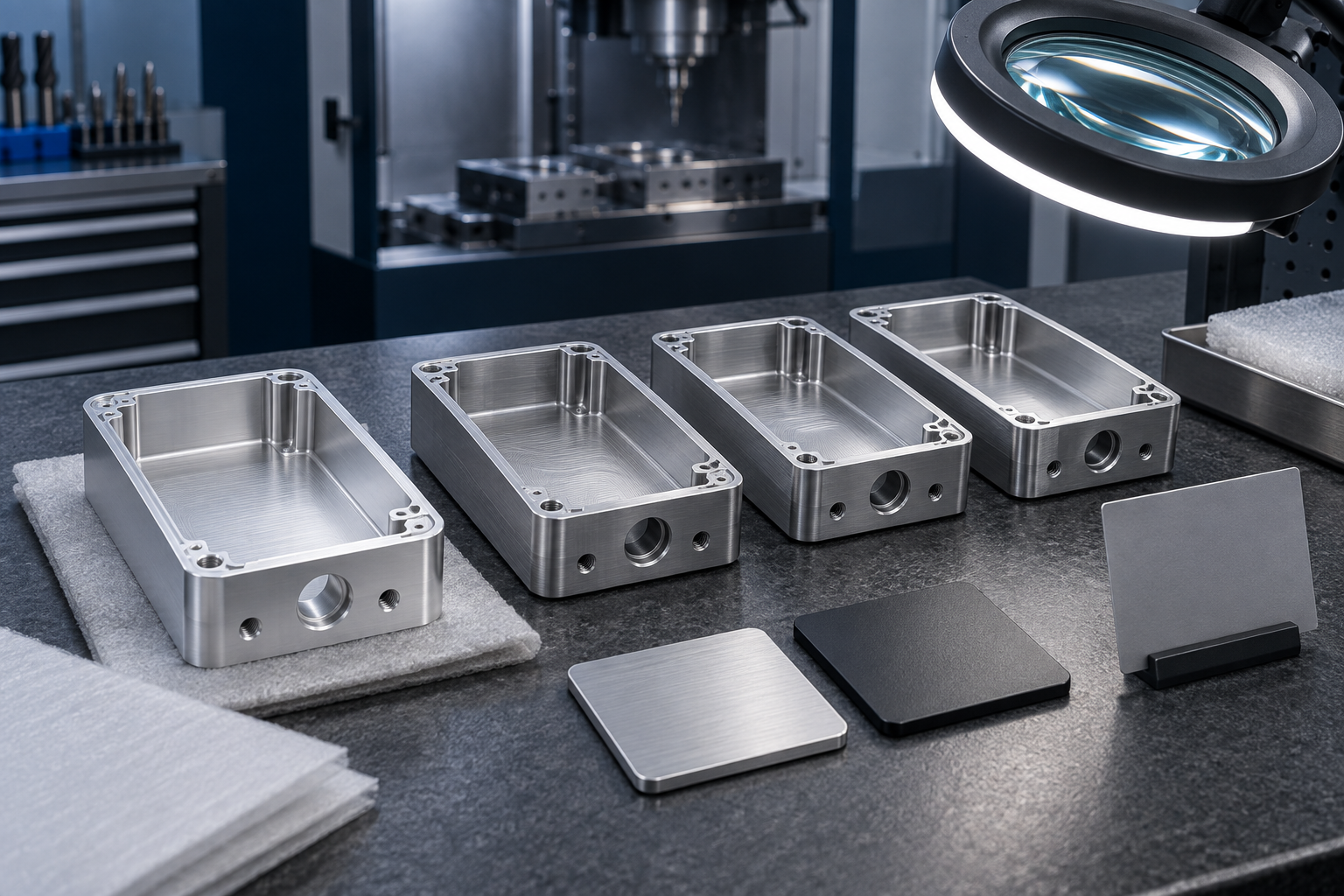
Use this five-step cosmetic release process
- Map visibility: mark primary, secondary, hidden, contact and excluded surfaces, including edges and installed orientation.
- Name defects: distinguish tool paths, scratches, dents, scuffs, stains, color variation and coating defects.
- Set inspectable limits: define size, count, spacing, zones, lighting, distance, angle, background and viewing time.
- Approve the full route: make samples using production material, machining, deburring, preparation and final finish.
- Protect the result: control handling, cleaning, trays, interleaf, film, transport and sample traceability.
Cosmetic quality is separate from dimensional conformance
A part can meet every size and geometric tolerance and still look unacceptable. Conversely, a minor visual mark on a hidden face may have no effect on fit or service. Cosmetic acceptance therefore needs its own drawing zones, defect language and inspection method.
Surface roughness controls profile characteristics over a measurement length. It does not automatically prohibit a scratch, dent, clamp witness, tool transition, stain or shade difference. A broad face may have acceptable Ra yet show an uneven milling pattern under raking light. Cosmetic requirements supplement functional texture rather than replace it.
Keep functional and cosmetic criteria linked where the same face serves both purposes. A visible sealing land, for example, may need texture, flatness, cleanliness and appearance limits. State which requirement controls if a polishing or coating operation could improve appearance while changing function.
There is no universal A, B or C cosmetic class
Many companies label surfaces A, B and C, but the letters have no universal severity. One organization may use A for the most visible face, while another uses a different hierarchy or more categories. The drawing must reference the company or project cosmetic standard that defines each class.
A practical classification can be built around how the customer encounters the product:
| Project-defined class | Typical visibility | Typical control focus | Required evidence |
|---|---|---|---|
| Primary cosmetic | Seen continuously in normal use or next to a matching component | Uniform texture, color, gloss, direction and strict isolated-defect limits | Production-representative limit samples and controlled viewing |
| Secondary cosmetic | Seen during installation, maintenance or occasional use | Consistent finish with a wider agreed defect allowance | Written defect criteria and reference sample |
| Hidden | Not visible after assembly | Functional finish, cleanliness and workmanship | Drawing and normal inspection records |
| Excluded or contact | Rack point, clamp zone, mask transition or sacrificial interface | Permitted witness type, maximum zone and functional protection | Location check and approved boundary example |
Mark these areas directly on the 2D drawing or controlled finish map. Include edges and radii; suppliers should not have to infer whether they belong to a primary face. For assemblies, show which parts are compared side by side and their installed orientation.
Create a cosmetic surface map
Use leaders, hatching or labeled views to identify each cosmetic face. Avoid relying on CAD display color alone unless the model-based definition procedure makes that color a controlled annotation. If only a portion of a face matters, dimension the boundary or relate it to stable datums.
The map should identify:
- primary, secondary and hidden surfaces;
- allowed rack, clamp and masking locations;
- grain or machining direction;
- areas compared across an assembly;
- areas that may show a tool-entry, blend or transition witness;
- features protected from blasting, brushing, anodizing or paint;
- edges, chamfers and radii included in each class.
Coordinate the map with aluminum CNC machining and the finish process. A cosmetic face used for hard clamping late in the route is likely to collect witness marks unless the fixture and protection plan are designed around it.
Use consistent defect names before setting limits
Teams often disagree because the same mark is called a scratch, tool line or scuff. ISO 8785:1998 establishes terms, definitions and parameters for surface imperfections and remained current after its 2025 review. A project cosmetic standard can use this type of vocabulary while adding photographs and product-specific definitions.
| Condition | How it differs | Likely origin | Specification question |
|---|---|---|---|
| Tool path | Regular pattern produced by intended cutting motion | Feed, stepover, cutter geometry and setup | Is the pattern allowed, and must direction be uniform? |
| Chatter | Unintended periodic pattern or vibration witness | Machine, tool, workholding or cutting stability | Is any visible chatter prohibited on primary faces? |
| Scratch or scuff | Linear or rubbed mark crossing the intended texture | Handling, chips, cleaning, transport or rework | What length, width, contrast, count and location are allowed? |
| Dent or nick | Local displaced material with depth or edge damage | Impact or part-to-part contact | Are protrusions, sharp edges or depth permitted? |
| Pit or inclusion witness | Small depression or substrate discontinuity | Material, corrosion, machining or chemical treatment | What size, density and cluster rule apply? |
| Stain or residue | Color or gloss change without intended texture | Coolant, cleaner, rinse, fingerprint or packaging | Must the mark be removable with the approved cleaning method? |
| Color or gloss variation | Area differs from its reference or neighboring part | Material, preparation, coating, orientation or lighting | Is acceptance visual, instrumental or both? |
Write defect limits that can be inspected
“No defects” is rarely a complete manufacturing instruction. Define which defect types are prohibited and which may occur within a controlled size, contrast, count, spacing or zone. Use separate rules for primary, secondary and excluded surfaces.
Do not copy numeric limits from an unrelated supplier chart. Acceptability depends on product size, normal viewing distance, finish texture, color, lighting, assembly proximity and market expectation. Develop limits with representative samples, then record the agreed values in a revision-controlled standard.
Include cluster rules. Several individually acceptable marks close together may create an objectionable patch. Also state whether a defect crossing an edge, logo area, display opening or adjacent-part boundary receives different treatment. If rework is allowed, define the permitted method and require it to meet the same final appearance.
Define inspection distance, light and orientation
Directional aluminum changes as the part or light moves. A scratch may disappear under diffuse light and become prominent under a raking source. Two anodized parts can look different when one is rotated relative to its extrusion or machining direction. An inspection method must therefore be repeatable and related to normal product use.
State:
- light source or booth condition and whether raking light is part of the review;
- viewing distance, angle and part orientation;
- neutral background and cleanliness condition;
- maximum inspection time per defined area;
- whether magnification is prohibited, optional or required for a separate functional check;
- observer qualification where color matching is critical.
ASTM D1729-22 describes equipment and procedures for visual appraisal of color differences on diffusely illuminated opaque materials. Its scope notes that metallic and pearlescent materials may need different directional illumination because those effects fall beyond the basic diffuse method. The project must confirm applicability to its aluminum finish.
Separate tool marks from random damage
Regular cutter marks are part of an as-machined surface unless the drawing requires their removal or a controlled visual pattern. Random cross-direction scratches, clamp dents, chip drag and hand-blended patches arise from a different mechanism. Combining both under “no tool marks” makes investigation and process correction difficult.
For CNC machining, define whether visible stepovers, circular face-mill patterns, blend lines between setups and entry or exit witnesses are acceptable. Mark any face requiring a continuous direction. If a later bead blast or brush treatment is intended, validate that it can equalize the surface without rounding edges or changing critical geometry.
Ra can support machining control but cannot replace visual limits. Two faces with similar average roughness can have different spacing, waviness, direction and reflectance. ASME B46.1 defines roughness, waviness, lay and related texture parameters, but isolated cosmetic defects still need separate acceptance criteria. Do not assume a finer Ra automatically creates a premium appearance.
Plan deburring and edge appearance
A sharp edge may be unsafe or unsuitable for coating, but uncontrolled hand deburring can produce bright facets of inconsistent width. Specify edge break geometry where it matters and state whether the bevel or radius is part of the cosmetic face. Define acceptable intersections at countersinks, slots and openings.
Small burrs can become more visible after anodizing, while aggressive blending can leave a halo. Cross holes and internal intersections need separate functional deburring even if they are hidden. Avoid a universal “break all edges” note when selected sealing, locating or datum edges require different treatment.
Inspect edges under the same finish condition as the face. A part should not pass cosmetic inspection before anodizing if the final coating changes contrast and exposes inconsistent edge work.
Specify blasting, brushing or polishing before coating
Mechanical preparation creates the texture that remains visible through many later finishes. The drawing should identify the process family, applicable surfaces, directional requirement, protected areas and approved sample. Media type, condition, pressure, angle, distance or abrasive wear may become controlled production variables after approval.
Brushing creates directional lay and needs a datum-related grain arrow. Blasting is more random but can show uneven dwell, shadowing, media contamination or edge effects. Polishing can reveal waves and local blending. No one process automatically removes every machining mark.
Coordinate these operations with surface finishing and engineering support. Deep pockets, bosses and undercuts may prevent uniform access; changing the geometry or finish boundary can be more repeatable than demanding the same appearance everywhere.
Anodizing reveals the substrate and preparation
Anodizing forms a transparent or translucent conformal oxide rather than an opaque filler. Alloy, temper, material lot, product form, cutting pattern, blasting, etching, coating formation, coloring and sealing can all influence the final appearance. A defect hidden on bare aluminum may become easier to see after anodizing.
The Aluminum Anodizers Council specification bulletin explains how alloy and preparation affect appearance. Its anodized aluminum FAQ recommends project-specific color range samples and notes that the exact material lot matters when close matching is required. Approve final samples using the intended material and complete route. The 6061 vs 6063 guide provides additional alloy and product-form context.
For anodized aluminum, mark rack contact and masked areas, identify surfaces that must match, and state whether color inspection is visual, instrumental or both. A black or clear designation alone does not control gloss, substrate streaks or local shade patterns.
Use color measurement with a visual correlation
Instrumental color data can improve repeatability when the method is complete. ASTM D2244-25 covers calculations of color differences from measured color coordinates. The standard emphasizes agreement between purchaser and seller on the permitted tolerance and calculation method, and it notes that texture, gloss and specimen proximity can affect commercial acceptance.
Define the reference specimen, instrument geometry, illuminant, observer, aperture, orientation, backing, measurement locations, averaging and color-difference equation. Do not compare values generated with different configurations as if they were interchangeable. Metallic and directional surfaces may require multi-angle or carefully oriented methods.
Use instrument limits to support, not contradict, the approved visual intent. A single overall color-difference value can hide whether the shift is in lightness, hue or chroma. Preserve component data where troubleshooting requires the direction of change.
Inspect texture, gloss and color as different characteristics
A surface can look darker because its actual color changed, its gloss decreased, its texture became coarser or its orientation changed. Those conditions have different causes. The inspection plan should not label all of them “color variation.”
Texture inspection considers machining or preparation pattern, uniformity, waviness and isolated defects. Gloss inspection requires an agreed method and geometry appropriate to the surface. Color inspection compares the finish with an approved reference. The part may need to pass all three, but each result should remain identifiable.
On adjacent parts, compare the assembly under normal orientation before relying on isolated coupon measurements. A small flat coupon may not represent a curved enclosure, long extrusion or face containing several machining setups.
Make limit samples representative and traceable
A golden sample represents a target; high and low limit samples define acceptable boundaries. Use production alloy, temper, product form, geometry and final finish where possible. Include examples of important allowable and rejectable conditions, not just one ideal part.
Assign each sample an identifier, drawing revision, approval date and storage owner. Keep a protected master and working inspection samples. Aluminum surfaces can scratch, fade, stain or age, so define how samples are periodically compared and replaced and connect their status to the project’s quality records.
Photographs can help identify defect location and terminology but should not be the only color or texture standard. Camera exposure, white balance, compression and displays change appearance. Record lighting and orientation for any supporting photographs.
Control handling from machine to shipment
Cosmetic quality can be lost after all process checks pass. Chips under a part, metal baskets, hard cleaning cloths, unprotected gauges and part-to-part movement create scratches and dents. Fingerprints, coolant residue and incompatible cleaners can become stains after chemical finishing.
Develop a one-direction material flow with clean trays, soft contact points and separated work in process. Identify when gloves, protective film or interleaf are required, and validate that film adhesive will not transfer or react with the final finish. Inspection fixtures should contact hidden or protected zones.
Packaging is part of the control plan. Prevent relative movement, surface rubbing, trapped debris, moisture and mixed lots. Include unpacking instructions when the customer must preserve orientation or remove protective film at a defined assembly stage.
Common cosmetic failures and first checks
| Observed issue | Investigate first | Useful evidence | Avoid assuming |
|---|---|---|---|
| Repeated lines on every part | Tool path, stepover, cutter condition and setup transition | Tool history and face orientation | Every visible line is handling damage |
| Random bright scratches | Chips, trays, cleaning, gauges and packaging | Process-stage photos and contact audit | Anodizing created a deep scratch |
| Patch after local repair | Blend direction, abrasive wear and dwell | Rework record and limit sample | More polishing will automatically match |
| Color varies by part or face | Alloy lot, product form, preparation, rack position and orientation | Material and finish lot map | The dye alone caused the shift |
| Halos near edges or holes | Deburring, blasting access, masking and current distribution | Geometry-specific sample | One flat coupon represents the feature |
| Parts pass alone but fail in assembly | Grain direction, adjacency and viewing conditions | Assembly-level comparison | Individual measurements guarantee visual match |
| Parts arrive marked | Interleaf, movement, debris and unpacking | Packaging trial and incoming photos | Final inspection proves delivery condition |
A practical cosmetic-control workflow
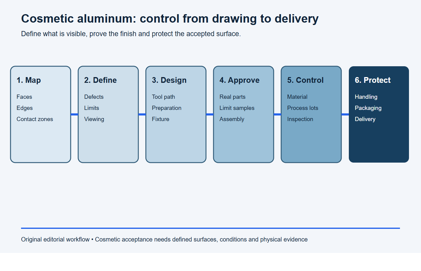
- Map: classify faces, edges, matching surfaces and allowed contact zones.
- Define: name defects and set project-specific limits and viewing conditions.
- Design: align machining, deburring, preparation, coating and fixture access.
- Approve: validate representative parts and physical limit samples.
- Control: trace material, tools, finish lots, samples and inspection results.
- Protect: manage cleaning, handling, packaging, transport and assembly.
Stop conditions: the cosmetic requirement is not ready
- The drawing says only “Class A,” “premium” or “no defects” without a referenced project definition.
- Edges, radii, adjacent matching parts or normal installed orientation are missing from the surface map.
- Tool paths, random damage and coating defects are grouped under one subjective rejection rule.
- The approved sample uses different material, machining, preparation or anodizing from production.
- Viewing conditions, limit samples, permitted contact zones or packaging protection remain undefined.
Copy-ready cosmetic-quality review request
Please review cosmetic requirements for part [number/revision]. Use the attached surface map to classify primary, secondary, hidden and permitted contact areas. Define each defect by type, maximum size, count, spacing and cluster rule under [lighting, distance, angle, orientation, background and viewing time]. Produce target and limit samples with production material, machining, deburring, preparation and finish. State color, gloss and texture methods, allowed rack/clamp locations, rework rules and packaging needed to protect accepted parts.
Cosmetic-requirement checklist for an RFQ
- controlled 3D model, 2D drawing and finish-standard revisions;
- alloy, temper, product form and any lot-matching requirement;
- surface map showing primary, secondary, hidden and contact zones;
- machining-pattern and grain-direction requirements;
- defined defect names, size, count, spacing and cluster limits;
- deburring and edge-appearance requirements;
- mechanical preparation and final coating specification;
- color, gloss and texture acceptance methods;
- viewing light, distance, angle, orientation, background and time;
- approved target and limit samples;
- masking, rack, clamp and rework zones;
- cleaning, handling, packaging and adjacent-part matching requirements.
Send the complete package through the BAOSONG project review form. Early agreement on what will be seen and how it will be judged reduces subjective decisions after production.
Frequently asked questions
Does a low Ra guarantee a cosmetic CNC surface?
No. Ra does not define tool-path uniformity, scratches, dents, waviness, reflectivity, color or gloss. Use a functional texture requirement together with visual criteria and samples.
What is a Class A cosmetic surface?
There is no universal definition. Class A often means a highly visible surface, but the drawing must reference the project standard that defines inspection conditions and allowable defects.
Can bead blasting hide all machining marks?
No. Blasting can equalize texture, but deeper tool transitions, dents and local repairs may remain visible. It can also affect edges and dimensions. Validate the complete route on representative geometry.
Why do matching aluminum parts look different after anodizing?
Material lot, product form, machining, preparation, rack position, oxide, coloring, sealing and viewing direction can all contribute. Preserve lot and process records before changing one variable.
Is a photograph enough for cosmetic approval?
No. Use photographs to illustrate defects and locations. Control color and texture with physical samples, written viewing conditions and instrumental methods where appropriate.
When should cosmetic inspection occur?
Inspect at relevant process gates and after the final finish. The delivery requirement should also be verified after packaging validation because handling can damage an accepted surface.
Request a cosmetic aluminum part review
BAOSONG can review CNC geometry, surface zoning, tool-path intent, mechanical preparation, anodizing, inspection and packaging as one cosmetic-quality system. Share the drawing, finish specification and reference samples through contact us for project-specific feedback.
Recommended Downloads for Aluminum Surface Finish Control
Use these BAOSONG references to select a finish, define cosmetic acceptance and prepare a production-ready requirement.
- Aluminum Surface Finish Selection Guide (PDF)
- Anodizing Guide: Color, Masking & Cosmetic Standards (PDF)
- Powder Coating, Brushing & Polishing Guide (PDF)
- Surface Finish Comparison Chart (editable Excel)
- Cosmetic Surface Requirement Template (editable Excel)
- Appearance Requirement Template (editable Excel)
Need help matching color, masking, gloss or cosmetic zones to your drawing? Contact BAOSONG engineering support.
