
Quick answer: what should you consider when CNC machining aluminum extrusions?
Treat the extrusion and the secondary machining as two linked manufacturing stages. The profile supplies a near-net cross-section and continuous features; CNC machining adds the controlled holes, slots, faces, pockets and datum interfaces that the assembly actually needs. A robust design states which requirements belong to the extruded profile, which belong to the machined features and how the two coordinate systems relate.
The main risks are using an as-extruded surface as if it were a precision-machined datum, overconstraining twist or straightness across a long flexible profile, clamping thin sections until they distort, and ignoring the effect of cutting, deburring or finishing on the final condition. These risks grow when a long part must be indexed through multiple setups.
A good design keeps the benefits of extrusion while concentrating CNC work on functional interfaces. It does not apply tight machined tolerances to the whole profile unless the assembly truly requires them. The practical process and inspection plan must be reviewed for the alloy, temper, cross-section, length, quantity and finished state.
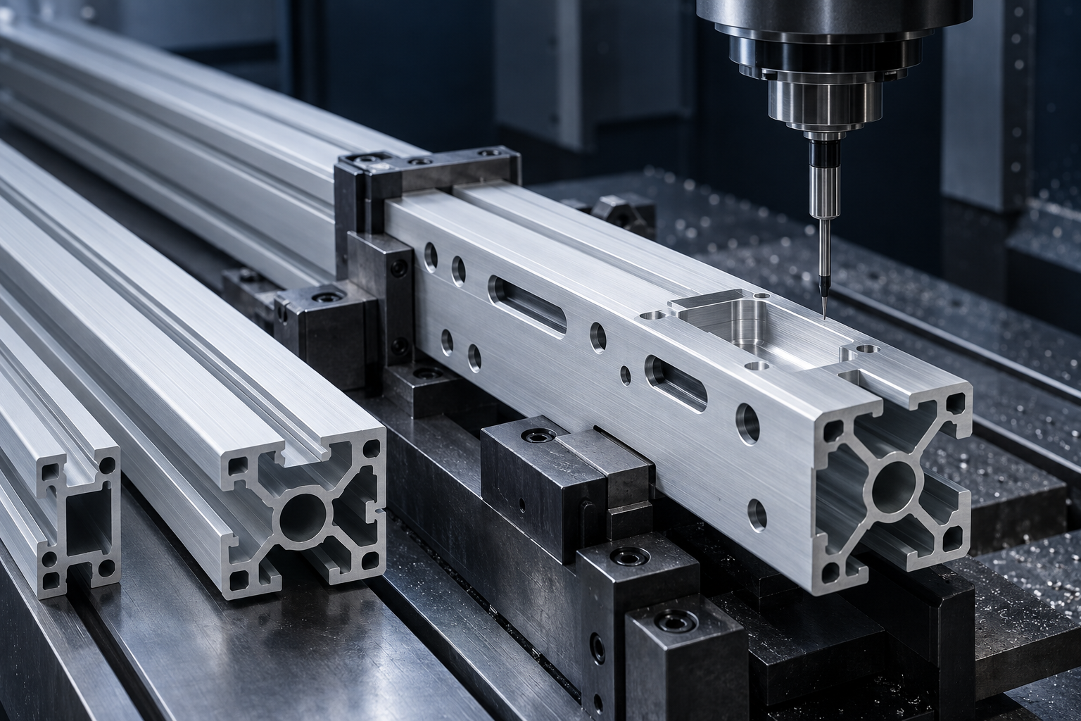
Seven-step extrusion machining design process
| Step | Decision | Required output |
|---|---|---|
| 1 | Assign continuous geometry to extrusion and local features to CNC | Feature-to-process map |
| 2 | Release the complete profile specification | Alloy, temper, section, length and source requirements |
| 3 | Separate profile and machined tolerances | Two-level acceptance plan |
| 4 | Build functional datums and workholding | Datum simulation and clamp/support plan |
| 5 | Review holes, ends, long setups, walls and chips | Machining sequence and access controls |
| 6 | Coordinate finishing and feature control | Final-state drawing and control chain |
| 7 | Inspect, validate and control changes | First-article and repeat-production plan |
Step 1: assign geometry to extrusion or CNC machining
| Design need | Best assigned to extrusion | Best assigned to CNC machining | Interface question |
|---|---|---|---|
| Continuous section | Walls, ribs, channels, T-slots, hollow paths and repeated cross-sectional mass. | Local changes that cannot run through the complete length. | Which section dimensions control stock, clearance and clamp contact? |
| Assembly location | Broad guide surfaces where standard profile variation is acceptable. | Datum pads, precision bores, hole patterns, end faces and local shoulders. | How are machined datums related to the extruded section? |
| Cut length | Long stock or near-net blanks. | Controlled final ends, steps, connector faces and calibrated length features. | Does final length apply before or after end machining and finishing? |
| Appearance | Consistent exposed longitudinal surfaces and designed shadow lines. | Localized cosmetic faces, edge breaks and protected interfaces where needed. | Which surfaces are visible, masked, handled or later anodized? |
If most of the material must still be removed, the extrusion may not be providing enough near-net value. Compare tooling, minimum order, straightening, machining fixtures, material yield and design-change flexibility with the alternative route. The guide When Aluminum Extrusion Is Better Than Machining from Solid Billet covers that upstream process decision.
Step 2: release the complete extrusion specification
“Aluminum profile” is not a complete purchase description. State the alloy, temper, cross-section revision, product standard, length condition, required surface state and approved substitutions. Identify whether the CNC supplier receives mill-length material, pre-cut blanks or finished profiles from a nominated extruder.
The Aluminum Association maintains the alloy and temper designation systems and publishes extrusion-specific standards and design references through its standards bookstore. Its official extrusion tolerance video series explains categories such as twist, straightness, flatness, and metal versus space dimensions used with ANSI H35.2 and Aluminum Standards and Data. Use the edition and tables required by the contract rather than copying values from an unrelated profile.
Temper affects mechanical properties and the manufacturing history of the product. It does not by itself guarantee straightness, residual stress, anodizing color or finished-part tolerance. For the distinction among common tempers, see Aluminum Temper Explained: T5, T6, T651 and What They Mean.
Step 3: separate profile and machined-feature tolerances
An extrusion drawing controls the produced cross-section and long-length condition. A machined-part drawing controls the finished component. Problems arise when a buyer expects every point on an as-extruded surface to behave like a machined plane or expects a local machined feature to correct the complete length of a twisted profile.
Create an explicit hierarchy:
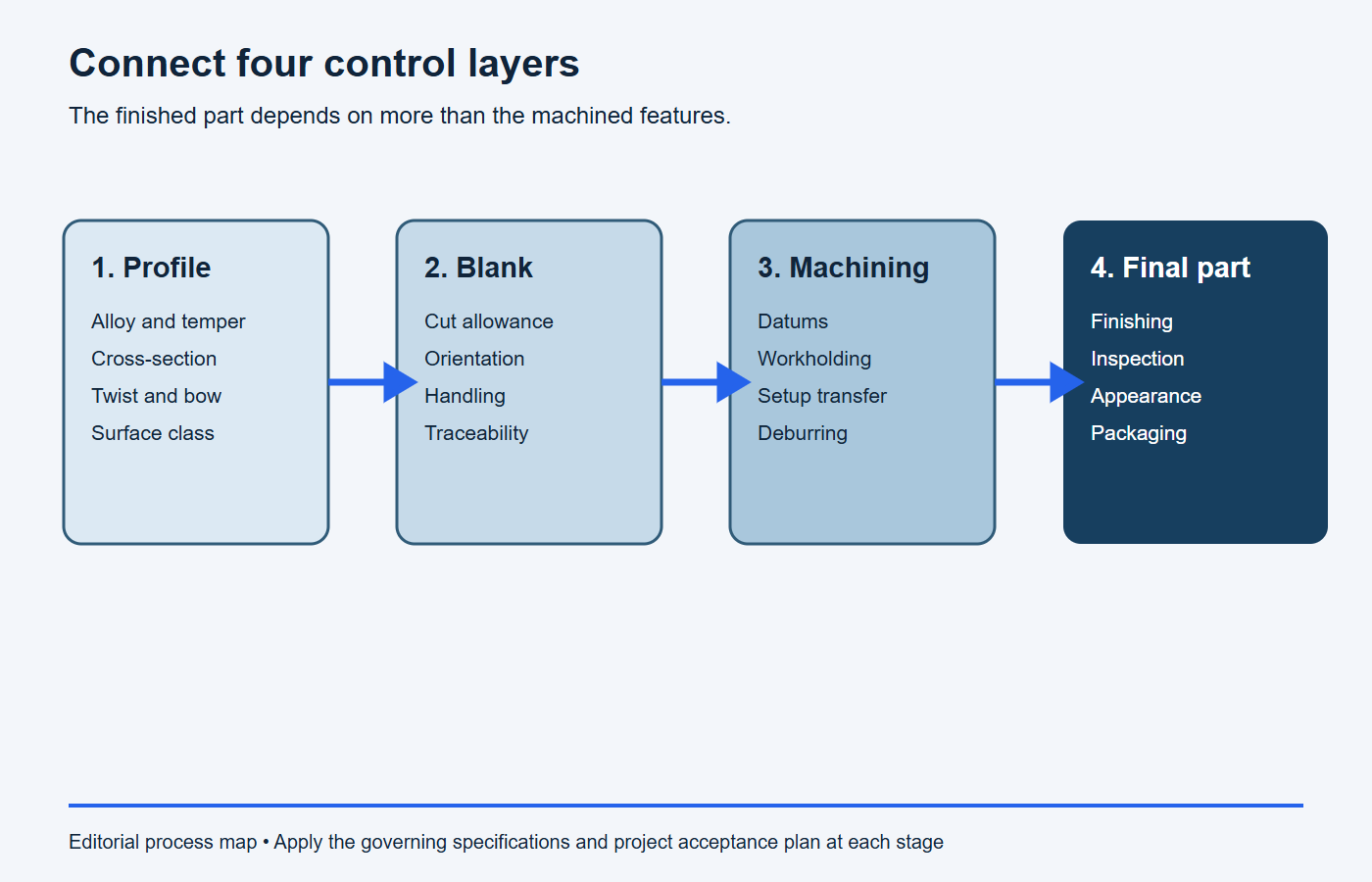
- Profile requirements: section dimensions, wall or rib relationships, twist, straightness, flatness and surface class.
- Blank requirements: cut allowance, end condition, handling protection and traceability.
- Machined requirements: datums, faces, holes, slots, pockets, threads, edge breaks and local geometric controls.
- Finished-state requirements: anodizing or coating, masking, appearance, final dimensions and inspection stage.
Do not apply one title-block tolerance to the extruded section and machined features without defining its scope. A tolerance suitable for a drilled mounting hole may be inappropriate for a long as-extruded channel. The companion guide on practical aluminum CNC machining tolerances explains why acceptance should be assigned by feature and function.
Step 4: build datums and workholding around assembly function
A useful datum reference frame locates the part the way the assembly needs it while remaining practical to establish during machining and inspection. Long extrusions often contain broad, slightly variable surfaces. Selecting the entire unmachined surface as a primary datum can create unstable or ambiguous contact, especially if the profile is bowed or twisted.
Consider machining local datum pads, end faces, bores or slots when the product needs repeatable location. The fixture can reference robust features during production, while inspection recreates the drawing datum scheme. If an as-extruded surface must be a datum because it contacts the assembly, define how it is simulated and whether high points, a limited area or another functional condition controls the part.
ASME describes Y14.5-2018 (R2024) as establishing symbols, rules and definitions for dimensioning and tolerancing. Use the drawing system and edition specified by the project. The standard supplies a common language; the designer still must select datums from product function.
Plan workholding without crushing or bending the profile
Extrusions can combine thin walls, open channels, hollow chambers and long unsupported spans. A vise or clamp may distort the section during cutting. If the profile springs back after release, holes or faces that were correct in the restrained condition may no longer meet the free-state requirement.
Fixtures may use shaped soft jaws, nests, internal mandrels, distributed supports, vacuum, modular stops or sacrificial tabs depending on the profile. The design should provide repeatable locating areas and clamp zones with enough local stiffness. Avoid placing critical cosmetic surfaces directly under hard clamps unless protection and witness-mark criteria are agreed.
Support strategy is part of process planning, not a generic promise. A short rigid extrusion blank may be held like a conventional prismatic part. A long rail may need several supports and a sequence that limits accumulated bow. A thin hollow profile may need internal support near drilling or slotting. The acceptable restraint must match the drawing’s free-state or restrained-state definition.
Step 5: design machined features around the section
Locate holes where the tool can approach without colliding with adjacent walls, flanges or clamps. Through-holes can simplify chip evacuation, while blind features need defined bottom geometry and enough access for the selected cutter or drill. If a hole crosses an angled or curved wall, the entry condition can cause drill wander or leave an uneven exit burr.
Extruded screw bosses and internal channels can reduce machining, but their as-extruded position and size must be compatible with the final thread or bore. Leave sufficient material for cleanup and consider how section variation shifts the available stock. Do not assume the nominal CAD centerline is the actual center of every produced profile.
Thread choice depends on wall thickness, engagement length, assembly load, service cycles and repair strategy. A tapped hole, thread-forming approach, insert, cross-nut or separate fastener can each be appropriate. Keep chips out of enclosed channels and specify whether the part must be cleaned before assembly.
Manage cut ends and end-face machining
Sawing creates a blank quickly but does not automatically produce the final datum, length, squareness, burr condition or appearance. The Aluminum Association’s historical selected tables include a category for squareness of cut ends, illustrating that cut condition is a defined extrusion consideration rather than an assumed perfect plane.
If an end face locates the assembly, machine it as a controlled feature and relate it to the chosen datums. Long parts may need both ends machined in separate setups or indexed through a machine. State whether total length, parallelism, hole-to-end distance or a functional stop is the critical requirement. Avoid redundant dimensions that create conflicting acceptance criteria.
Control error when long profiles require multiple setups
A machine’s travel may be shorter than the extrusion. Repositioning or index machining can extend the workable length, but every relocation introduces datum-transfer and measurement questions. A chain of coordinate moves is not the same as a direct relationship between two functional features.
Use robust locating features and define which end or assembly interface is primary. Where possible, place related holes or slots within one setup. For repeated patterns, decide whether pitch, cumulative position from one datum or local module-to-module spacing protects the product. The drawing should express that function rather than dimensioning every feature from its nearest neighbor by habit.
Multi-axis equipment may improve access to several sides and reduce reclamping for shorter parts, but it does not remove profile bow or long-length indexing. Review multi-axis aluminum CNC machining and keep long-part handling as a separate capability question.
Account for thin walls, burrs and chip control
Thin flanges can deflect during milling. Drilling near an unsupported edge can raise a burr or distort the wall. Long internal channels can trap chips, cutting fluid and debris. These effects influence tool direction, feature order, support, deburring access and cleaning.
Specify edge-break intent rather than demanding an undefined “no burr” condition. Identify sealing edges, electrical contact areas, sliding tracks and cosmetic surfaces that need special protection. On inaccessible internal channels, agree how cleanliness will be verified. Review these access and stiffness constraints as part of the aluminum CNC milling plan.
Step 6: coordinate machining, finishing and feature control
Decide whether the extrusion is finished before machining, machined before finishing or processed in a mixed sequence. Machining a pre-anodized profile exposes bare aluminum at cut faces and holes. Anodizing after machining covers accessible machined surfaces but changes masking, racking and dimensional acceptance requirements.
Color and gloss can vary with alloy, temper, extrusion history, surface preparation, geometry and process lot. Do not promise exact appearance from a generic color name. Establish visual zones, approved samples where applicable, acceptable racking locations and rules for exposed cut edges.
For functional surfaces, state which dimensions apply after finishing and which areas are masked. Align the drawing with the surface-finishing specification and the requirements for anodized aluminum components.
Use a feature-to-process control plan
The diagram and table below convert the product definition into four linked control layers. This is a planning model, not a BAOSONG capability statement.
| Control layer | Required input | Main production question | Verification record |
|---|---|---|---|
| Extruded profile | Alloy, temper, cross-section revision, tolerance standard and surface class. | Does incoming stock provide enough material and acceptable long-length form? | Material record, profile inspection and agreed incoming sampling. |
| Cut blank | Cut allowance, handling, orientation and traceability. | Can the blank be located and supported without losing its identity or finish? | Blank length/condition check and lot identification. |
| Machined interfaces | Functional datums, holes, slots, faces, threads and geometric controls. | Can related features be produced in one setup or with controlled datum transfer? | First article, in-process checks and final dimensional report as specified. |
| Finished component | Finish standard, mask zones, cosmetic criteria and final acceptance condition. | Do finishing, deburring and cleaning preserve functional interfaces? | Final dimensional, visual and cleanliness records required by the order. |
Step 7: inspect using the same datum logic
Measure profile characteristics and machined characteristics against their applicable specifications. A caliper check across one local section does not establish twist over the complete length. A CMM report of machined holes does not by itself confirm that a flexible rail will sit correctly in the assembly.
Long parts need an agreed support condition and temperature strategy. Contact force, gravity and restraint can affect flexible profiles. NIST’s publication on uncertainty and dimensional calibrations explains that dimensional results are estimates with associated uncertainty. Match the instrument, fixture, sampling and decision rule to the feature and tolerance.
For high-value repeat production, connect drawing characteristics to the quality and inspection plan. Define first-article scope, critical-feature sampling, material traceability and how changes to the extrusion source or die revision are controlled.
Production release checklist
- The profile drawing and finished-part drawing use matching revisions and a defined coordinate relationship.
- Alloy, temper, extrusion standard, source responsibility and incoming condition are stated.
- Every requirement is assigned to extrusion, sawing, CNC, deburring, finishing or final inspection.
- Workholding supports the section without crushing, bending or marking functional and cosmetic surfaces.
- Long-part indexing, end machining, hole access, burr removal and internal cleanliness are planned.
- The first article is measured in the specified support, temperature and finished condition.
- Die, profile source, machining fixture and finishing changes require documented review.
Stop conditions: the extrusion machining plan is not ready
- The CNC supplier has only the finished model and no profile drawing or source information.
- An as-extruded surface is used as a precision datum without defining how it is contacted.
- One tight title-block tolerance is applied to both profile and machined features.
- Machining allowance does not cover profile variation and cleanup.
- The fixture restrains a flexible rail, but free-state acceptance is undefined.
- Long features cross setups without a datum-transfer and cumulative-position plan.
- Anodizing, masking, exposed cut ends and post-finish dimensions are unresolved.
Copy-ready aluminum-extrusion machining RFQ checklist
- Finished-part 3D model and 2D drawing with matching revision.
- Extrusion cross-section drawing and die/profile revision.
- Alloy, temper, governing extrusion standard and product condition.
- Source responsibility: customer-supplied profile, nominated extruder or supplier sourcing.
- Critical machined datums, interfaces and acceptance condition.
- Cut length, end-face, deburring and cleanliness requirements.
- Finish, masking, cosmetic zones and approved sample requirements.
- Part length, prototype quantity, production quantity and repeat forecast.
- Inspection report, sampling and traceability requirements.
- Packaging and protection for long finished profiles.
Use BAOSONG’s engineering-support resources to prepare the drawing review, or send the profile and finished-part requirements for a manufacturability discussion. The review should identify the few interfaces that justify precision machining and keep the remaining cross-section within a suitable extrusion specification.
Frequently asked questions
Can an as-extruded surface be used as a machining datum?
It can be used when that matches assembly function and its variation is acceptable, but the drawing and fixture must define how the surface is contacted. For more stable precision relationships, local machined pads, faces or bores may provide clearer datums.
Should holes be dimensioned from the end of an extrusion?
Only if the end is a controlled functional datum. A saw-cut end and a machined end have different roles. State whether final length and hole location apply after end machining and finishing.
Is T-slot extrusion automatically ready for precision assembly?
No. Standard modular profiles can be excellent for frames, but slot, straightness, cut-end and assembly variation still need to match the application. Precision mounting faces or locating holes may require secondary machining.
Should aluminum extrusions be anodized before or after CNC machining?
Either sequence can be appropriate. Pre-anodized stock preserves the longitudinal finish but leaves bare machined areas. Post-machining anodizing covers accessible features but adds masking, racking, color and final-dimension considerations. Choose from the functional and cosmetic requirements.
Recommended Downloads for Aluminum Extrusion Design
Use these BAOSONG references to set profile geometry, wall thickness, tolerances and downstream CNC features before releasing an extrusion design.
- Custom Aluminum Extrusion Design Guide (PDF)
- Wall Thickness and Tolerance Guide (PDF)
- CNC Machining Guide for Aluminum Extrusions (PDF)
- Aluminum Alloy Comparison Chart (editable Excel)
Need help checking an extrusion profile or manufacturability risk? Contact BAOSONG Precision.
