
Quick answer: what should engineers specify for a brushed aluminum finish?
A brushed aluminum finish is a directional mechanical texture made by moving an abrasive across the metal in a controlled path. For production, the drawing should identify the cosmetic surfaces, grain direction, acceptable start and stop zones, protected features, downstream coating, and an approved physical appearance sample.
Do not approve brushed aluminum from a grit number or surface-roughness value alone. Abrasive type and condition, pressure, feed speed, passes, substrate, lighting and viewing direction all affect appearance. Ra or Rz can support process control, but neither fully describes line spacing, reflectivity, waviness, isolated scratches or visual uniformity.
Design the finish together with forming, welding, CNC machining and anodizing. Features that cannot be reached in one controlled direction, mixed material lots, repair blending and poor packaging can make otherwise conforming parts look inconsistent. Early agreement on an actual finished sample is the most practical way to align design, production and inspection.
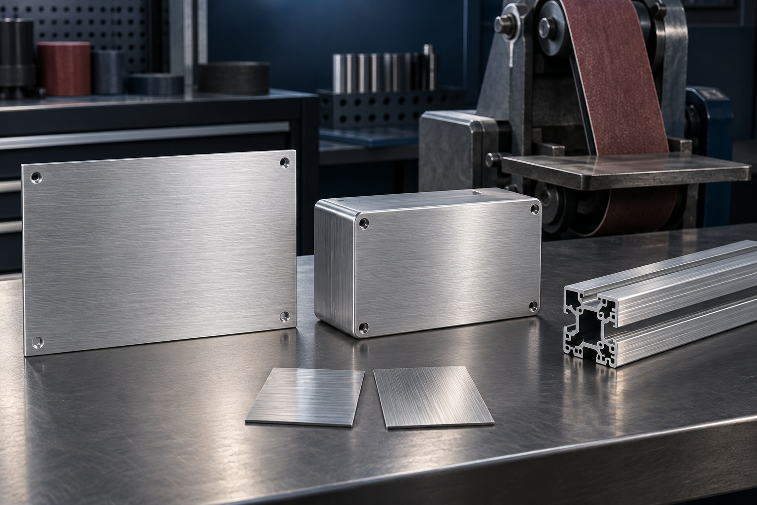
Use this four-step brushed-finish release process
- Map the visible surfaces: classify cosmetic zones and mark grain direction, boundaries and protected interfaces.
- Build the full route: set material, machining, fabrication, brushing, cleaning, anodizing or coating in the intended order.
- Approve limit samples: use production-representative material and geometry under stated lighting, distance and orientation.
- Lock control and protection: record process variables, inspection criteria, interleaf, film, cleanliness and handling rules.
What is a brushed aluminum finish?
Brushing removes or displaces a small amount of surface material with an abrasive belt, wheel, pad or comparable tool. The moving abrasive creates fine, substantially parallel lines known as the surface lay. The result is less mirror-like than polishing and more directional than a random satin or bead-blasted texture.
The Aluminum Anodizers Council describes mechanical finishing as a step used before chemical finishing or anodizing and distinguishes directional from non-directional textures. Its finish designation system places brushed finishes within the M35 directional-texture group. The designation identifies a finish family; it does not replace the supplier-customer sample that defines the exact appearance.
Brushing can reduce the visual contrast of minor handling marks and establish a premium, repeatable design language. It is not a coating and does not provide corrosion protection by itself. Bare brushed aluminum can oxidize, stain or collect fingerprints, so the complete finish system may include cleaning, anodizing, a clear organic coating or another validated protection method.
Turn the visual intent into a production specification
| Decision | Define on the drawing or finish standard | Why it matters |
|---|---|---|
| Cosmetic surfaces | Classify primary, secondary and non-cosmetic faces | Prevents the same visual limit being applied to hidden and customer-facing areas |
| Grain direction | Use an arrow or datum-related direction on every visible face | Rotated parts reflect light differently even when their texture is otherwise similar |
| Finish boundary | Show where brushing starts, stops and may blend | Transitions near edges, bosses and pockets can become visually obvious |
| Reference | Approve representative minimum and maximum limit samples | A written adjective such as “fine satin” is open to interpretation |
| Downstream treatment | State bare, anodized, conversion coated or clear coated | The later process changes tone, gloss and corrosion behavior |
| Inspection conditions | Set lighting, distance, angle, orientation and viewing time | Directional metal can pass in one orientation and appear different in another |
| Handling and packaging | Define film, interleaf, cleanliness and contact limits | Rubbing, adhesive residue and fingerprints can damage an accepted finish |
Control grain direction across the product
Grain direction is usually the first design decision because it controls how the surface catches light. On a door, bezel or enclosure panel, the brush direction may follow the longest dimension. On an assembled product, adjacent panels should usually share a deliberate orientation. If one panel is rotated 90 degrees, it can look lighter or darker beside the others.
Place a clear grain arrow on the drawing and relate it to a part datum, not to a drawing sheet that may be rotated. For nested sheet parts, include the orientation requirement in the cutting plan. For symmetric parts, add an orientation mark or packaging instruction so assembly cannot reverse the intended appearance.
Three-dimensional parts require extra judgment. A belt can create a stable direction on a broad flat face, but it may roll over a radius or become inaccessible inside a pocket. Decide whether grain should continue around a corner, stop at a break line, or be limited to one face. A sharp visual boundary is often easier to control than an undefined hand-blended transition.
Select the brushing route around the part geometry
Wide abrasive belts suit flat panels and long faces because motion, pressure and feed can be controlled over a large area. Abrasive wheels or nonwoven media can reach shaped surfaces, but contact pressure and local dwell become more sensitive. Hand brushing is useful for prototypes, local blending and low-volume work, yet it increases operator dependence and should not be assumed to match an automated line.
Specify the result and validated process window rather than copying a grit number from another project. “240 grit,” for example, does not uniquely determine appearance across abrasive brands, mineral types, backing systems, machine speeds or wear states. A worn belt can cut differently from a new belt, and a process may change gradually before visual defects become obvious.
For an RFQ, send a representative CAD model and identify the expected production quantity. BAOSONG can then review the brushing route together with CNC machining, metal fabrication and surface finishing instead of treating appearance as an isolated final operation.
Substrate, alloy and product form remain visible
Brushing modifies the topography but does not make every aluminum substrate look identical. Rolled sheet, extrusion and machined billet begin with different grain structures and surface histories. Alloy, temper, mill finish, material lot and prior heat exposure can influence how a brushed surface responds to cleaning and anodizing.
Mill lines, extrusion streaks, die pickup, dents, pits and deep machining marks may remain after normal brushing. Removing them can require more stock removal, which may change flatness, corner definition or dimensions. Mark critical cosmetic faces on incoming material and protect them before cutting, forming and transport. Do not expect the finish station to erase damage without engineering review.
Mixed product forms are especially difficult to match on one visible assembly. A machined 6061 body, a 5052 sheet cover and a 6063 extruded trim can each meet its material specification yet respond differently after brushing and anodizing. The 6061 vs 6063 aluminum guide explains why alloy and manufacturing route should be selected together.
Design edges, holes and recesses for finish access
Edges concentrate abrasive pressure and can round faster than broad faces. A narrow land beside a hole may receive less stable contact, while a raised boss can shadow the area behind it. Deep pockets, internal corners and closely spaced ribs may be unreachable in the chosen grain direction. These are geometry constraints, not inspection problems.
Review these details before releasing the drawing:
- provide enough flat access for the chosen belt, wheel or pad;
- keep important text, sealing lands and precision datums out of uncontrolled blend zones;
- define whether edges are brushed, deburred only or masked;
- place holes and countersinks so brush lines do not create unacceptable halos;
- protect threaded holes, bearing fits, electrical contacts and grounding areas as required;
- use break lines or separate components when two incompatible grain directions would meet.
When finish access conflicts with function, a removable cosmetic panel or a pre-brushed sheet route may be more stable than trying to brush a fully machined enclosure. Our engineering support review can identify these conflicts before tooling or production fixtures are committed.
Do not use roughness alone to approve appearance
Surface texture has several components. Roughness describes relatively fine irregularities, waviness describes broader spacing, and lay describes the predominant direction. ASME B46.1 addresses terminology and methods for roughness, waviness and lay. These measurements help engineers control a process, but a single parameter cannot capture the complete appearance of directional aluminum.
Two surfaces can have similar Ra values yet differ in line spacing, isolated scratches, gloss or reflectivity. Measurement direction matters because a stylus crossing the grain reads a different profile from one traveling along it. Cutoff, filter, evaluation length, instrument tip and sampling location must be defined if a numerical texture requirement is used.
Use roughness where it supports function or process stability, and use approved visual limit samples for appearance. The sample should use the production alloy, product form, geometry and complete finish stack. Keep a protected master and working references; record their approval date and replacement method so gradual sample wear does not shift acceptance.
Plan CNC machining and brushing in the right sequence
Machining before brushing lets the finish blend light tool marks on accessible faces, but the abrasive can soften edges and affect a very tight functional surface if it is not protected. Machining after brushing preserves critical features, yet clamps, chips and coolant can scratch or stain the cosmetic face. There is no universal sequence.
For aluminum CNC machining, separate functional and cosmetic requirements. Identify datums and fits that must not be brushed, define masking where necessary, and plan soft jaws or protective films for later operations. Do not use a cosmetic surface as an unprotected locating face.
Tool paths can become part of the final appearance if they are deeper than the brushing process removes. If a face must look uniformly linear, allow a process trial to confirm that machining marks can be blended without excessive stock removal. Reworking only one local area often leaves a patch with a different line density or reflection.
Brushing before anodizing changes the final appearance
Anodizing creates a conformal oxide over the prepared aluminum surface. The Aluminum Anodizers Council’s specification bulletin explains that the oxide is transparent or translucent and that the substrate and mechanical preparation influence the visible result. Brushed lines therefore remain part of the anodized appearance.
Chemical etching before anodizing can soften contrast and change gloss, while bright dipping can move the finish in another direction. Clear and colored anodizing can reveal differences among alloys, lots, weld zones and product forms. Approving bare brushed metal does not prove that the anodized production part will match.
Specify the complete route, such as brush, clean, pretreat, anodize, color and seal. Approve samples after the final process. See BAOSONG’s anodized aluminum service for the downstream finish context, and use the Aluminum Association designation system to communicate finish categories consistently.
Forming and welding can disrupt a uniform brush
Pre-brushed sheet can simplify broad-panel appearance, but bending changes how the grain reflects on each face and may mark the material at tooling contact points. Protective film must tolerate cutting and forming without trapping debris or leaving adhesive residue. The brush direction relative to a bend also affects the visual result.
Weld beads, heat-affected zones and blended repairs can remain visible after brushing and anodizing. Weld metal may differ chemically from the parent material. If a seamless appearance is required, produce a welded and finished sample using the actual alloy, filler, preparation and heat input. A flat sheet coupon is not representative.
Choose the sequence around the whole assembly: cut, form, weld, blend, brush, clean and coat. Each handling step after brushing needs a protection plan. If components can be finished separately and assembled with hidden fasteners, this may improve repeatability, but the visible grain direction and color still need assembly-level approval.
Control batch consistency through the process window
A stable process records more than the nominal abrasive. It controls abrasive manufacturer and product, belt or wheel condition, contact wheel, pressure, speed, feed, number of passes, overlap, part orientation, cleaning and operator or machine program. Relevant variables should be frozen after sample approval.
New and worn abrasive may need defined change limits. Parts produced at the beginning and end of a run should be compared under the same conditions. If multiple workstations are used, verify that they produce equivalent results before mixing output. Keep material and finish lots traceable so a visual pattern can be linked to its likely cause.
Process capability should be evaluated on real cosmetic areas, not only small flat coupons. Long panels expose waviness and banding that a coupon may hide. Complex enclosures expose direction changes and edge blending. First-article review should include the assembled orientation when adjacent-part matching matters.
Define inspection so appearance decisions are repeatable
Visual inspection is most useful when the conditions are written and practical. Specify a neutral background, diffuse or otherwise agreed illumination, viewing distance, observation angle, part orientation and reasonable viewing time. Clean the part with the approved method before comparison; fingerprints and residue can mimic finish variation.
Inspect for the agreed defect classes: wrong grain direction, cross-grain scratches, chatter, banding, blotches, edge roll, incomplete coverage, embedded abrasive, stains and handling damage. Separate continuous process texture from isolated defects. If color and gloss matter after anodizing, evaluate them as additional characteristics rather than calling everything “brushing.”
BAOSONG’s quality approach can support drawing-based inspection and traceability. The purchase specification still needs project-specific acceptance evidence. A generic online photograph cannot serve as a color or texture standard because capture, compression and display conditions change what the viewer sees.
Common appearance problems and likely controls
| Observed condition | Investigate first | Useful control |
|---|---|---|
| Panels look different when assembled | Grain orientation, material lot and viewing direction | Datum-based arrows, nested orientation and assembly-level sample |
| Dark or light bands across a face | Feed overlap, belt wear, pressure and substrate waviness | Validated machine settings and abrasive change criteria |
| Cross-grain lines | Handling, prior machining, debris or local rework | One-direction flow, cleaning and protected transfer |
| Rounded edges or lost definition | Excess dwell and edge pressure | Fixture support, pass control and defined finish boundary |
| Halos around holes or bosses | Tool access and contact-pressure changes | Geometry review, stable fixture and approved local limit |
| Brushed parts differ after anodizing | Alloy, lot, pretreatment, oxide, color and seal | Approve the complete finish route on production-representative samples |
| Acceptable parts arrive scratched | Film, interleaf, part-to-part contact and unpacking | Validated packaging and handling instructions |
A practical brushed-finish control workflow
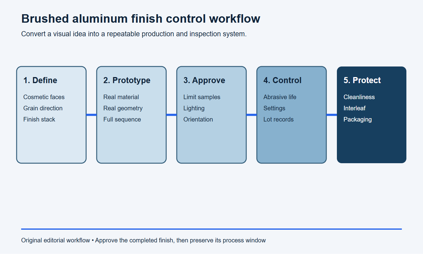
- Define: classify faces, mark grain direction and state downstream finishing.
- Prototype: make representative parts using the intended material, geometry and process sequence.
- Approve: agree physical limit samples and inspection conditions.
- Control: record material lots, abrasive condition, machine settings and finish batches.
- Protect: clean, package, label orientation and prevent rubbing through delivery and assembly.
Stop conditions: do not approve the brushed finish yet
- The requirement is only a grit number, Ra value or adjective such as “fine satin.”
- Grain direction and cosmetic boundaries are missing from one or more visible faces.
- The sample uses different alloy, product form, machining, geometry or downstream finish from production.
- Recesses, corners, welds or repaired areas cannot be brushed in the approved direction with repeatable access.
- Inspection lighting, limit samples, packaging protection or protective-film removal is undefined.
Copy-ready brushed aluminum finish request
Please develop a brushed finish for part [number/revision], alloy/temper/product form [requirement]. Use the drawing’s cosmetic-face classes and grain arrows. State abrasive system, process direction, finish boundaries, protected features and the complete sequence through anodizing or coating. Produce representative minimum, target and maximum appearance samples and propose visual inspection conditions plus supporting texture measurements. Quote packaging, interleaf, film and handling needed to preserve the accepted surface.
What to include in a brushed aluminum RFQ
- 3D model and controlled 2D drawing revision;
- alloy, temper and product form;
- primary and secondary cosmetic surfaces;
- datum-related grain arrows for every relevant face;
- areas where brushing, edge roll, rack contact or masking is allowed;
- functional dimensions and surfaces that must be protected;
- complete finish route, including anodizing or coating if required;
- approved sample, limit samples or target-development plan;
- visual inspection conditions and any supporting texture measurements;
- prototype and production quantities, assembly relationship and packaging needs.
Send these inputs through the BAOSONG project review form. The goal is to confirm that the drawing, process access, sample and acceptance method describe the same finished product before production begins.
Frequently asked questions
Is brushed aluminum the same as satin aluminum?
Not necessarily. “Brushed” usually describes a visibly directional mechanical texture. “Satin” is used inconsistently and may describe a finer directional finish or a more uniform non-directional appearance. Define the intended result with a process-aware sample.
What grit creates the best brushed aluminum finish?
There is no universal best grit. The result depends on abrasive system, machine, wear, pressure, speed, passes, substrate and later treatment. Select the appearance on representative samples, then control the validated variables.
Can Ra specify a brushed appearance?
Ra can support texture control, but it does not define grain direction, gloss, line density, isolated scratches or waviness. Use measurement parameters together with lay requirements and visual limit samples.
Does anodizing hide scratches in brushed aluminum?
No. The anodic oxide follows the surface and can leave scratches and inconsistent preparation visible. Repair or reject objectionable damage before anodizing, then approve the appearance after the complete finish route.
Should aluminum be brushed before or after machining?
The sequence depends on which faces are cosmetic, which dimensions are critical and how later work will be protected. Review machining access, edge effects, fixturing and stock removal before choosing the sequence.
How should brushed aluminum be packaged?
Use clean, non-abrasive separation and protection validated for the final finish. Prevent part-to-part movement, trapped chips, moisture, adhesive residue and mixed orientation. Define when protective film is removed.
Request a brushed aluminum finish review
BAOSONG can review alloy, geometry, machining or fabrication sequence, directional finishing, anodizing and inspection as one production system. Share the drawing, cosmetic-face map, target sample and expected quantity through contact us for a project-specific manufacturability and finish review.
Recommended Downloads for Aluminum Surface Finish Control
Use these BAOSONG references to select a finish, define cosmetic acceptance and prepare a production-ready requirement.
- Aluminum Surface Finish Selection Guide (PDF)
- Anodizing Guide: Color, Masking & Cosmetic Standards (PDF)
- Powder Coating, Brushing & Polishing Guide (PDF)
- Surface Finish Comparison Chart (editable Excel)
- Cosmetic Surface Requirement Template (editable Excel)
- Appearance Requirement Template (editable Excel)
Need help matching color, masking, gloss or cosmetic zones to your drawing? Contact BAOSONG engineering support.
