
Quick answer: what is the practical difference between as-machined and polished aluminum?
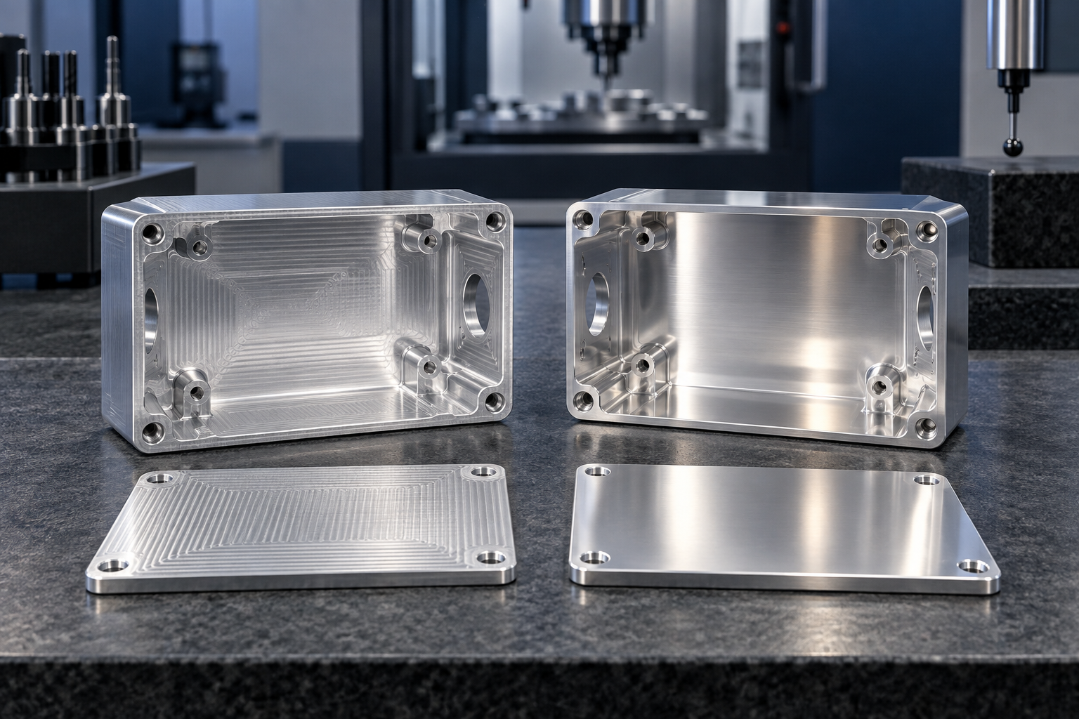
An as-machined aluminum finish is the surface left by the final cutting operation, followed by normal cleaning and specified deburring. Controlled tool paths remain visible. A polished finish adds abrasive refinement after machining to reduce or remove those patterns and produce a smoother, brighter or more reflective appearance.
As-machined is usually the lower-risk choice for tight geometry, inaccessible features, prototypes and hidden functional parts. Polishing suits customer-facing surfaces, reflectors or parts needing a deliberately refined appearance, but it adds labor, access constraints and the possibility of edge rounding, local waviness, dimensional change and batch variation.
Neither term is a complete specification. Define the surfaces, roughness or appearance requirement, tool-path or polish direction, allowed defects, protected dimensions, downstream coating and inspection method. For polished work, approve production-representative physical samples because “satin,” “bright” and “mirror” do not have one universal meaning.
Use this four-step finish selection
- Classify the surfaces: mark functional, primary cosmetic, secondary cosmetic, hidden and protected areas.
- Choose by purpose: retain as-machined tool paths where they are acceptable and polish only where appearance or optical function earns the added work.
- Check process access: review abrasive reach, edge rounding, dimensional stock, transitions and downstream coating.
- Approve the final state: inspect representative parts with measurements, physical limit samples and packaging protection.
As-machined finish preserves the final cutting pattern
Milling and turning create a repeatable surface pattern from cutter geometry, feed, stepover, tool engagement, machine motion and material response. The pattern may be linear, circular, spiral or contoured. A clean pattern is not automatically a defect; it is the expected record of the chosen machining strategy unless the drawing says otherwise.
As-machined also does not mean rough, dirty or unfinished. The part should meet the drawing, be free from harmful burrs and contamination, and show workmanship consistent with the specified surface. Tool chatter, gouges, chip drag, clamp damage and random scratches are different from an intentional tool path.
For aluminum CNC machining, designers can request a texture parameter, a controlled tool-path direction or cosmetic limit samples on selected faces. Avoid applying one fine finish requirement to every pocket and hidden wall when only a few areas influence function or appearance.
“Polished” covers several different results
Polishing removes progressively smaller surface irregularities with abrasives. Buffing may follow to increase brightness and reduce visible abrasive lines. The route can involve belts, discs, wheels, compounds, automated equipment or skilled hand work. Different combinations can produce matte-smooth, satin, bright or highly specular results.
The Aluminum Anodizers Council specification guide lists polishing and buffing among mechanical finishing processes and explains that they can create appearances ranging from directional or non-directional texture to specular finish. Its finish designation summary separates buffed, directional-textured and non-directional finish families.
A word such as “polished” therefore needs supporting detail. State which faces are polished, the intended direction, target roughness when function requires it, gloss or reflectance method if relevant, allowed residual lines, edge condition and a physical appearance reference. If the exact process is critical, reference a qualified process specification.
As-machined and polished finishes at a glance
| Decision factor | As-machined | Polished | Customer should define |
|---|---|---|---|
| Appearance | Visible, controlled cutting pattern | Reduced abrasive lines with satin to bright reflection | Reference sample, direction and defect limits |
| Geometry | Final shape produced directly by CNC | Additional stock removal and possible edge blending | Protected datums, radii, edges and dimensions |
| Access | Limited mainly by cutter and machine access | Limited by belt, wheel, pad and operator access | Faces, pockets and transitions included |
| Consistency | Driven by tool, program, workholding and material | Also driven by abrasive wear, pressure, dwell and operator | Process window and sample plan |
| Inspection | Texture measurement and workmanship review | Texture plus visual, gloss or reflectance assessment | Method, orientation, locations and limits |
| Downstream finish | Tool paths may remain visible through anodizing | Polish state influences final brightness and uniformity | Approve the complete finish route |
| Handling | Clean aluminum still marks and oxidizes | Bright surfaces readily reveal fingerprints and fine scratches | Cleaning, film, interleaf and packaging |
Surface roughness does not fully describe appearance
Surface texture includes roughness, waviness and lay. ASME B46.1 defines these constituents and parameters for quantifying surface texture. ISO 21920-1:2021 provides rules for indicating profile surface texture in ISO-based technical product documentation.
A lower Ra often accompanies abrasive refinement, but the number does not define brightness, line spacing, waviness, isolated scratches, pits or direction. Two surfaces can have similar Ra values and look different under the same light. A highly reflective face can make minor distortion more visible even when its fine roughness is low.
If roughness matters, state the parameter, units, maximum or range, measurement direction, filter conditions and locations. Use appearance samples for appearance. A stylus trace across an accessible flat coupon cannot prove that every corner and pocket on a complex housing was polished uniformly.
Tool paths can be an intentional design feature
Many premium industrial products use controlled circular or linear machining patterns as part of their visual identity. This route can preserve sharp geometry and produce repeatable machine-defined direction without manual polishing. It works best when the designer accepts the pattern and specifies how adjacent faces or parts should align.
Large flat faces show tool transitions, stepover changes and reflection more readily than small features. A finishing pass may need its own tool, stable workholding and controlled entry or exit. Multi-setup parts can show different patterns on different orientations even when every face meets the same roughness value.
Identify customer-facing surfaces on the drawing, and distinguish permitted regular tool paths from chatter, gouges or random damage. The CNC machining plan should preserve cutter, program and setup controls for repeat orders.
Polishing changes edges and local geometry
Abrasive contact is not perfectly uniform. External edges receive concentrated pressure and can round or lose definition. Raised lettering and narrow lands can soften. Local dwell can dish a flat surface, and thin walls can distort under pressure or heat. A polished part can look smoother while moving away from its intended geometry.
Mark sealing lands, bearing seats, datums, sharp visual breaks and precision fits that must not be polished. Define whether chamfers and radii are included. If a cosmetic face meets a functional edge, agree how the finish stops or blends before approving the design.
Dimensions should be assessed in the required final condition. Do not assume polishing removes a negligible amount everywhere, and do not add a universal stock allowance. Use a representative trial to establish machining stock and process capability for the actual material, geometry and target finish.
Deep pockets and internal features may not polish uniformly
A wide belt or wheel can produce a stable finish on an open face but may not reach a deep pocket, narrow channel or internal corner. Small tools can reach more areas but increase local variation and time. Hand access can also become unsafe or inconsistent on thin ribs and sharp geometry.
Decide whether internal faces remain as-machined, receive a different finish, or need a design change. A clear finish boundary at an edge or step is often more repeatable than an undefined blend inside a pocket. Avoid requiring mirror-like appearance on features that cannot be viewed normally and do not contribute to function.
Use engineering support to review abrasive access before finalizing the part. A removable cover, separate trim, larger radius or accessible face orientation may achieve the intended appearance with less risk.
Polishing cannot reliably erase every defect
Deep cutter steps, dents, pits, porosity and material inclusions may require substantial removal and can remain visible after polishing. Removing one local defect can create a low spot or a patch with different reflection. Repeating the operation across the whole face may alter dimensions and edges.
Inspect material and machining before polishing. Define the maximum condition that the polish route is expected to remove, and route deeper defects for engineering disposition. Do not rely on a final bright surface to conceal cracks, corrosion or substrate discontinuities.
The Aluminum Association Designation System for Aluminum Finishes organizes mechanical finishes, chemical finishes and coatings as separate but combinable categories. Use that framework to describe the complete preparation sequence, then apply current project specifications and approved samples for production decisions.
Alloy and stock form influence the polished result
Aluminum alloys and product forms differ in chemistry, microstructure, inclusions, grain flow and prior surface condition. Rolled sheet, extrusion, billet and cast material may polish differently. A machined assembly made from mixed forms can show different tone or reflectivity even after similar abrasive work.
Material lot changes can affect cosmetic matching. Keep visible matched parts within a controlled material and finish lot where feasible. Mark the alloy, temper and product form on the drawing, and do not substitute based only on strength if appearance and anodizing matter.
The 6061 vs 6063 aluminum guide explains how alloy selection relates to machining and extrusion. Produce appearance samples from the intended stock route rather than approving an unrelated generic coupon.
Polished aluminum needs a protection strategy
Bare aluminum naturally develops a surface oxide, and bright polished faces reveal fingerprints, stains, cleaning streaks and fine scratches readily. The delivered appearance depends on cleaning, storage and packaging as much as the last polishing step.
Possible protection routes include anodizing, a compatible clear organic coating or application-specific handling controls. Each changes appearance and performance. A clear coating may alter gloss or visual depth. Anodizing follows the substrate and can change tone. No route should be selected only because it is called “clear.”
Define approved cleaners, glove use, protective film, interleaf, part-to-part separation and unpacking. Verify that film adhesive and packaging materials do not mark or react with the finished surface during expected storage and transport.
Anodizing preserves evidence of both starting finishes
The Aluminum Anodizers Council explains that uncolored anodic oxide is transparent or translucent and conforms to the original texture. As-machined tool paths, polishing lines and substrate defects can remain visible. Chemical etching or brightening before anodizing may modify contrast, but it does not turn every starting surface into the same result.
Approve anodized samples after the complete mechanical preparation, cleaning, chemical pretreatment, anodizing, coloring and sealing route. The AAC specification bulletin notes that alloy and mechanical finish influence anodized appearance.
For anodized aluminum, identify rack-contact zones, masked features and color-match surfaces. A polished bare coupon is not evidence that the final anodized housing will retain the same brightness or match another alloy lot.
Functional surfaces may need a different finish choice
Appearance is only one decision. Seal faces, sliding interfaces, bearing seats, adhesive bonds, thermal contacts and optical elements can respond differently to texture and residual polishing compound. A very bright appearance does not prove the surface is suitable for its function.
Specify the functional parameter and cleaning requirement independently. Keep polishing away from critical datums or fits unless the validated process includes them. If friction, sealing, bonding or optical performance is critical, qualify the actual surface system with the mating material and service conditions.
Polishing can also remove sharp burrs unevenly without guaranteeing that intersecting holes are safe or clean. Maintain a separate deburring plan and inspect hidden intersections as functional features.
Inspection must match the finish type
As-machined inspection may combine texture measurement, visual review of the intended tool pattern and defect checks. Polished inspection may also consider gloss, reflectance, haze, direction and waviness. The instruments, geometry, units and locations must suit the surface.
For visual acceptance, define lighting, distance, angle, orientation, neutral background and viewing time. Highly reflective surfaces can show the inspection room rather than the part itself, so use controlled surroundings and compare the sample and part in the same orientation.
Keep approved target and limit samples under revision control. Connect them to the project’s quality records and protect master samples from scratches, oxidation and cleaning changes. Photographs can document defect location but should not be the only brightness or color standard.
What drives cost and production risk?
| Driver | Why it matters | Design response |
|---|---|---|
| Cosmetic area | Larger areas need more controlled machining, abrasive time and inspection | Limit premium finish to surfaces customers see or use |
| Geometry access | Pockets, ribs and intersections need smaller tools or manual work | Create clear finish boundaries and accessible radii |
| Brightness level | Finer refinement needs more stages and cleaner handling | Approve the least demanding appearance that serves the product |
| Defect removal | Deep marks require stock removal and risk distortion | Prevent damage upstream and define rework limits |
| Edge definition | Abrasive pressure can soften corners and features | Protect critical edges and dimension final condition |
| Batch matching | Material, abrasive wear and operator technique affect reflection | Control lots, settings and samples |
| Downstream coating | Anodizing or clear coat changes final tone and gloss | Approve the complete route, not an intermediate surface |
How to specify the expected finish
Use drawing notes and a finish map that identify the result without forcing unnecessary methods. Bracketed fields below are project decisions.
| Finish | Example note structure | Supporting definition |
|---|---|---|
| As-machined functional | SURFACE [A]: [TEXTURE PARAMETER/LIMIT/UNITS] PER [STANDARD]; MEASURE [LOCATIONS/DIRECTION] | Function, lay and final condition |
| As-machined cosmetic | SURFACE [B]: CONTROLLED [TOOL-PATH DIRECTION]; APPEARANCE PER LIMIT SAMPLE [ID/REV] | Allowed transitions and prohibited defects |
| Polished | POLISH SURFACES [C] TO [APPEARANCE/TEXTURE/REFLECTANCE REQUIREMENT]; DIRECTION [DATUM]; SAMPLE [ID/REV] | Process specification, protected edges and inspection |
| Polished and anodized | MECHANICAL FINISH [C], THEN ANODIZE PER [SPEC/TYPE/CLASS/COLOR/COATING REQUIREMENT] | Pretreatment, masking, contacts and final sample |
| Protected feature | DO NOT POLISH SURFACES [D]; FINAL DIMENSIONS AND TEXTURE APPLY AFTER ALL FINISHING | Mask boundary and allowable blend zone |
Common expectation gaps
- treating visible as-machined tool paths as defects when no cosmetic rule was specified;
- writing “mirror polish” without a sample, reflectance or defect method;
- assuming a roughness value guarantees the desired appearance;
- requiring identical polish inside inaccessible pockets and on broad faces;
- expecting polishing to remove deep dents or material defects without geometric change;
- omitting edge, datum, seal and precision-fit protection;
- approving bare polished metal when production will be anodized;
- comparing parts under different light or orientation;
- protecting the finish during production but not during shipment or assembly.
A practical finish-selection workflow
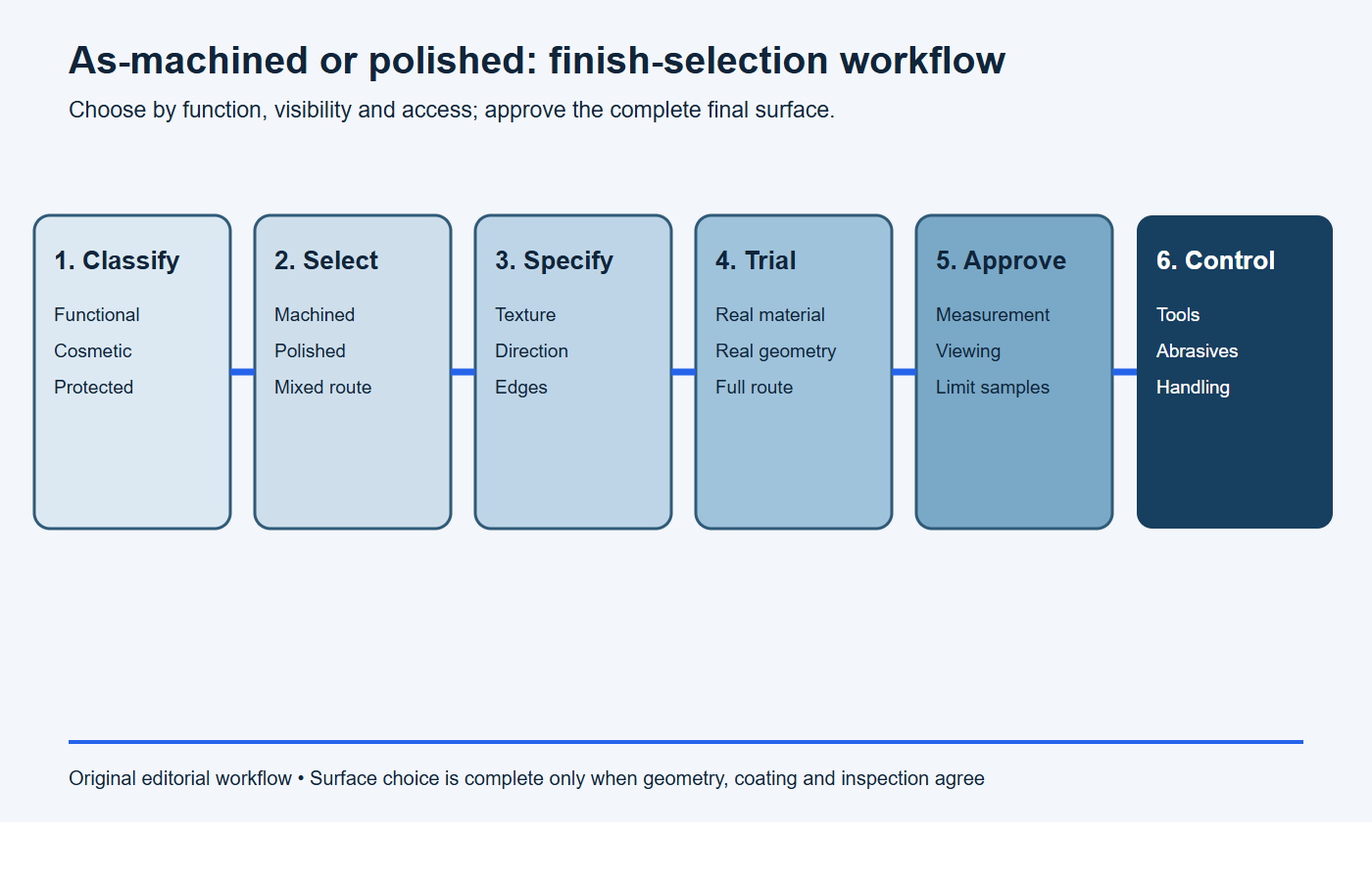
- Classify: identify functional, cosmetic, hidden and protected surfaces.
- Select: choose as-machined, polished or a mixed finish by surface.
- Specify: define texture, direction, edges, defects and downstream coating.
- Trial: process representative material and geometry through the complete route.
- Approve: agree measurements, viewing conditions and physical limit samples.
- Control: preserve tools, abrasives, lots, handling and packaging records.
Stop conditions: the finish expectation is not ready
- The requirement uses “polished,” “satin” or “mirror” without a surface map, direction and physical sample.
- As-machined tool paths, chatter, gouges and random scratches are not defined as different conditions.
- Polishing access, edge rounding, dimensional stock and protected datums have not been reviewed.
- The approval coupon uses different alloy, geometry or downstream anodizing from the production part.
- Cleaning, fingerprint control, interleaf, film and transport protection are absent from the finish plan.
Copy-ready as-machined or polished finish request
Please review part [number/revision] for an as-machined, polished or mixed finish. Use the surface map to identify each finish, tool-path or polish direction, protected datums, edge limits, allowed residual lines and final dimensions. State the machining and abrasive route, downstream anodizing/coating and inspection method. Produce production-representative target and limit samples, then quote cleaning, handling and packaging needed to preserve the approved appearance.
What to send with an RFQ
- controlled 3D model and 2D drawing revision;
- alloy, temper, stock form and matched-lot requirements;
- surface map identifying as-machined, polished and protected faces;
- functional texture parameters and measurement conditions;
- tool-path or polishing direction;
- allowed edge rounding, transitions and residual lines;
- approved target and limit samples;
- downstream anodizing or coating specification;
- dimensions that apply after finishing;
- cleaning, handling, packaging and assembly orientation;
- prototype and production quantities.
Send these inputs through the BAOSONG project review form. A clear finish definition allows quoting, manufacturing and inspection to evaluate the same deliverable.
Frequently asked questions
Is an as-machined aluminum finish acceptable for a customer-facing part?
Yes, when the tool pattern is intentional and approved. Define direction, transitions, defects and samples instead of assuming every visible part needs polishing.
Does polished always mean mirror finish?
No. Polished surfaces range from refined satin to highly specular. State the target appearance and inspection method, and approve representative samples.
Is polished aluminum always smoother than as-machined aluminum?
It often has lower fine roughness on accessible faces, but local waviness, edges and inaccessible areas can differ. Measure the parameter and locations that matter.
Will anodizing hide CNC tool marks?
No. Anodic oxide conforms to the surface, so tool paths and preparation differences may remain visible. Approve the final anodized route.
Can polished parts hold the same tolerances?
They can meet suitable final tolerances when stock, access and process capability are planned. Protect critical datums and inspect dimensions after the specified finish.
Which finish is less expensive?
As-machined usually avoids separate abrasive processing. Actual cost depends on cosmetic area, machining requirement, polish level, geometry, inspection, coating and quantity.
Request an aluminum finish review
BAOSONG can review machining strategy, polish access, cosmetic zones, final dimensions, anodizing and inspection as one production system. Share the drawing, finish requirement and reference samples through contact us for project-specific feedback.
Recommended Downloads for Aluminum Surface Finish Control
Use these BAOSONG references to select a finish, define cosmetic acceptance and prepare a production-ready requirement.
- Aluminum Surface Finish Selection Guide (PDF)
- Anodizing Guide: Color, Masking & Cosmetic Standards (PDF)
- Powder Coating, Brushing & Polishing Guide (PDF)
- Surface Finish Comparison Chart (editable Excel)
- Cosmetic Surface Requirement Template (editable Excel)
- Appearance Requirement Template (editable Excel)
Need help matching color, masking, gloss or cosmetic zones to your drawing? Contact BAOSONG engineering support.
