
Quick answer: why does anodized aluminum vary in color?
Anodized aluminum varies in color because the final appearance is created by the aluminum substrate, surface preparation, anodic oxide, coloring process, sealing and viewing conditions together. A difference at any stage can shift lightness, hue, gloss or texture even when every part is ordered under the same short color name.
The largest upstream causes are often mixed alloys, different material lots or product forms, inconsistent machining or blasting, and unequal chemical etching. Process causes include coating-thickness variation, electrical contact and current-distribution differences, bath condition, dye or electrolytic-coloring control, transfer time and sealing. Geometry and rack position can make the variation local rather than batch-wide.
Do not begin corrective action by changing the dye alone. First classify the pattern, confirm material traceability and surface preparation, then review anodizing, coloring, sealing and the inspection method in sequence. A useful specification defines an approved sample and comparison conditions instead of demanding an undefined “perfect match.”
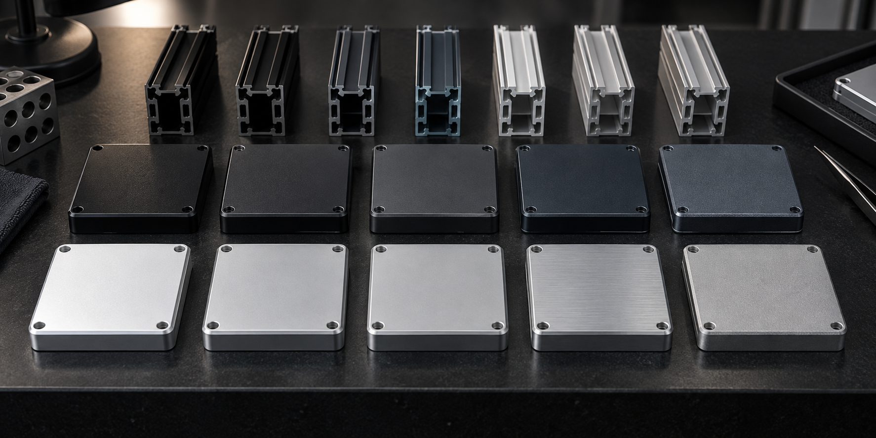
Use this sequence before changing the anodizing process
- Preserve the evidence: segregate affected lots and photograph the pattern with part, rack and surface locations recorded.
- Confirm the comparison: repeat visual or instrumental checks under the agreed light, orientation and measurement settings.
- Trace upstream first: compare alloy, material lot, product form, machining, welding, blasting and chemical preparation.
- Trace the finish: review oxide thickness, electrical contact, bath position, coloring, transfer time and sealing.
- Verify one controlled correction: approve representative samples and monitor the next production lot before closing the cause.
Start by separating color, gloss and texture
A part can look darker because its measured color changed, because the surface became more matte, or because directional machining reflects the light differently. Those are different conditions and may have different causes. The same specimen can appear acceptable from one angle and mismatched from another.
Before investigating production, describe what changed:
- Lightness: one part looks lighter or darker overall.
- Hue: the color shifts toward blue, green, red, bronze or another undertone.
- Gloss or reflectance: one surface is brighter, duller or more directional.
- Texture: grain, tool paths, etching or blasting changes the visual field.
- Uniformity: the variation is a patch, streak, edge band, rack shadow or whole-part shift.
ASTM E430-19 provides methods for measuring gloss on high-gloss surfaces, including metals. The selected instrument geometry and specimen condition must suit the product. Color and gloss should therefore be specified and assessed as separate properties rather than inferred from one visual impression.
The substrate is part of the anodized color
Anodizing creates a transparent or translucent oxide rather than an opaque paint film. Light interacts with the oxide, any added color and the metal beneath it. Differences in alloying elements and microstructure can change oxide formation and the appearance seen through the coating.
The Aluminum Anodizers Council specification bulletin states that alloy and temper affect anodized appearance, and that alloy series can respond differently under identical processes. It also explains that cast alloys and wrought alloys do not necessarily anodize alike.
Control these substrate variables when color matching matters:
- alloy designation and temper;
- material producer, heat or billet lot where practical;
- extruded, rolled, forged, cast or machined product form;
- weld metal and heat-affected zones;
- grain flow, local segregation and prior thermal history;
- rework material or mixed batches.
Two parts labeled “6061” are not automatically appearance-matched if they come from different lots, stock forms or surface histories. Our 6061 vs 6063 aluminum guide gives additional context for alloy and product-form selection.
Surface preparation changes how light returns to the eye
Machining, brushing, polishing, tumbling and abrasive blasting establish the initial texture. Chemical cleaning, deoxidizing, etching or brightening modifies it again before anodizing. Because the anodic coating follows the surface, preparation differences remain visible rather than being filled.
A fresh cutting tool and a worn tool may leave different reflectance even when dimensional results are equivalent. Changing blasting media, pressure, distance, angle or media condition can shift matte appearance. Unequal etch exposure can make one part darker or duller and can emphasize extrusion streaks or metallurgical bands.
Keep the manufacturing route consistent for matched cosmetic parts. Identify the required pre-anodize condition on the drawing and avoid mixing as-machined, hand-blended and reworked surfaces in one visual acceptance group. Coordinate the requirement with the CNC machining and surface-finishing plans.
Oxide thickness and pore structure influence color uptake
Anodizing current, time, temperature, electrolyte condition and part geometry affect how the oxide develops. Changes in coating thickness or pore structure can alter natural tone and the amount or distribution of absorbed color. Hard anodizing may show strong alloy-dependent natural shades even before any dye is considered.
Uneven electrical contact or current distribution can create local thickness and color differences. Edges, recesses and crowded rack positions may not behave like broad open faces. A pattern tied to geometry or rack orientation points the investigation toward current distribution, solution movement or handling rather than raw-material lot alone.
ASTM B244-09(2021) covers eddy-current measurement of nonconductive coatings on nonmagnetic basis metals. It notes that substrate conductivity must match the calibration reference. Thickness mapping is useful only when the instrument, calibration, geometry and measurement locations suit the part.
Dye and electrolytic coloring introduce additional variables
For absorbed dye systems, shade can respond to dye concentration, temperature, pH, contamination, immersion time, agitation, rinsing and the oxide’s absorptive capacity. A blended dye may also drift in hue if components deplete at different rates. Transfer delays between anodizing, coloring and sealing can change results.
Electrolytic coloring has different control variables, including the prepared pore structure, electrical conditions and metal deposition. Integral-color or interference systems follow still other mechanisms. A troubleshooting plan must first confirm which coloring method was used; “black anodize” or “bronze anodize” is not a process diagnosis.
When variation is limited to the top, bottom or edges of a rack, compare immersion timing, solution movement, electrical field and part orientation. When the entire batch shifts consistently, review material lot, pretreatment, bath analysis, coating target and coloring history.
Sealing can change shade and long-term stability
Sealing modifies the porous anodic coating after coloring. Seal chemistry, water quality, temperature, pH, time and contamination can affect appearance, dye bleeding, staining behavior and protective performance. The visible part at final inspection may also change later if the system or service exposure is unsuitable.
ASTM B680-24 describes an acid-dissolution method for evaluating seal quality of certain porous anodic coatings used for weathering, corrosive exposure or stain resistance. The method has explicit exclusions, so it should not be applied automatically to every anodizing category.
Keep sealing records linked to the production lot, and investigate whether a shade change occurred before sealing, immediately after sealing or after storage. This timing helps distinguish color uptake from seal-related or environmental change.
Geometry, racking and drainage create local patterns
Deep pockets, overlapping surfaces, blind cavities and narrow channels can trap solution, restrict rinsing or change local current and temperature conditions. Rack contacts interrupt the coating and may leave visible marks. Long extrusions can show differences along length or between faces because of original profile condition and process orientation.
Place rack contacts on agreed non-cosmetic surfaces. Add drainage and access where the process requires them, and orient cosmetic surfaces consistently. For anodized aluminum extrusions, review die lines, handling marks, cut ends and lengthwise appearance before production.
Heat, welding and mixed manufacturing routes can remain visible
Weld metal and heat-affected zones can have different chemistry and microstructure from the parent material. They may anodize to a different shade even after blending. Likewise, a machined insert, extruded body and cast end cap may not match because the substrates and surface preparations differ.
If visual continuity is essential, minimize mixed alloys and process routes on the same visible assembly. Produce representative finished samples using the actual materials, welding consumables, heat treatments and preparation. Do not approve a machined coupon as proof that a welded or cast production assembly will match.
Viewing conditions can create an apparent mismatch
Anodized aluminum is directional and reflective. Light source, viewing angle, background, nearby colors, surface orientation and distance can change perception. Two acceptable parts can look different when rotated relative to their machining or extrusion grain.
Instrumental color data can help, but it does not eliminate the need to define the method. ASTM D2244-25 covers calculation of color tolerances and differences from measured color coordinates. The instrument geometry, illuminant, observer settings, aperture, sample orientation and comparison equation must be aligned with the product requirement.
Visual approval should use controlled lighting, viewing distance, orientation and background. Decide which surfaces are compared and whether adjacent assembled parts require a tighter match than isolated components. Preserve an approved physical master and define how it will be replaced as it ages.
Use the variation pattern to narrow the cause
| Observed pattern | Investigate first | Records or checks | Do not assume |
|---|---|---|---|
| Whole batch shifted from approved sample | Material lot, preparation, bath and color history | Material certificates, process traveler, reference sample | The dye alone caused the change |
| Parts differ within one rack | Contact, current distribution, position and solution movement | Rack map, thickness map, orientation photos | All positions received the same condition |
| Edges darker or lighter than broad faces | Geometry, current density and coating distribution | Location-specific thickness and visual comparison | One average reading describes the part |
| Streaks follow extrusion or machining direction | Substrate, tooling and pretreatment | Raw profile review, tool history, etch record | More dye will hide the structure |
| Color changes after sealing or storage | Seal, rinsing, contamination and exposure | Seal test, water chemistry, storage and cleaning history | Final-tank color was stable |
| Parts match in one light but not another | Illuminant, metamerism, gloss and orientation | Controlled booth and agreed instrument settings | One photo is an acceptance standard |
A disciplined root-cause workflow
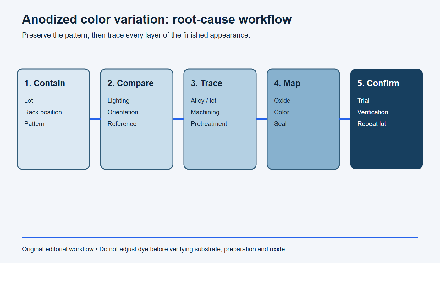
- Contain and document: identify lots, rack positions, surfaces and the exact visual pattern before sorting or rework.
- Verify comparison: reproduce the issue under agreed lighting, orientation and measurement settings.
- Trace upstream: compare alloy, heat or billet lot, product form, machining, blasting, welding and pretreatment.
- Map the process: review coating thickness, electrical contact, bath condition, coloring, transfer and sealing by position.
- Confirm correction: run a controlled sample, verify function and appearance, then monitor the next repeat lot.
Stop conditions: do not approve the corrective action yet
- The suspected cause was chosen from one photograph without reproducing the mismatch under controlled comparison conditions.
- Material lot, alloy, stock form, machining, blasting or pretreatment records are missing.
- The pattern by rack position, surface orientation, coating thickness, coloring and sealing has not been mapped.
- Multiple process variables were changed at once, so the actual cause cannot be confirmed.
- Re-anodizing is proposed without checking dimensional loss, surface change and feature risk from stripping.
Copy-ready anodized color investigation request
Please investigate color variation on part [number/revision], lot [identifier]. Preserve and map affected pieces by material lot, machining batch, rack position, orientation and surface. Compare them with approved sample [identifier] under [lighting, angle and instrumental settings]. Review alloy/product form, surface preparation, anodic coating thickness, electrical contact, bath position, coloring, transfer and sealing. Propose one controlled trial, state the expected evidence for the root cause and monitor the next production lot before closure.
How to prevent batch-to-batch color variation
- use one clearly specified alloy, temper and product form for matched visible parts;
- maintain material-lot traceability and avoid unapproved substitutions;
- standardize machining, brushing, blasting, polishing and chemical preparation;
- identify cosmetic faces, rack-contact areas and required part orientation;
- specify anodizing type, coating requirement, coloring method and sealing;
- approve production-representative samples instead of generic color chips;
- define visual and instrumental comparison conditions and acceptance limits;
- retain process and inspection records for repeat-order investigation;
- use packaging that prevents staining, rubbing and mixed-lot confusion.
ASTM B580-25 covers porous anodic oxide coatings used where appearance, abrasion resistance, electrical properties and corrosion protection matter. Use the project’s required standard and current edition, and select only the properties and tests that apply to the actual product.
Frequently asked questions
Is some anodized color variation normal?
Some variation is inherent because anodizing reveals substrate and process differences, but “normal” is not an acceptance criterion. Define an approved range, comparison conditions and the surfaces that must match.
Why do two 6061 parts anodize differently?
They may come from different material lots or product forms, have different heat or surface histories, or receive different preparation and rack conditions. Confirm traceability and processing before assuming the alloy designation is wrong.
Can darker anodizing hide machining marks?
Not reliably. Anodizing is not an opaque filler coating. Dark color may reduce some contrast, but tool paths, scratches and preparation differences can remain visible.
Can color variation be fixed by re-anodizing?
Sometimes a coating can be stripped and the part reprocessed, but stripping removes material and can affect dimensions, surface texture and fatigue-sensitive features. Engineering review is required before rework.
Is a photograph enough to approve anodized color?
No. Cameras, screens, white balance and lighting alter appearance. Use a physical reference or a defined instrumental method plus controlled visual review.
Request a finish and root-cause review
BAOSONG can review material traceability, manufacturing route, cosmetic surfaces, anodizing requirements and inspection evidence as one finished-part system. See our anodized aluminum, engineering support and quality approach, or send the drawing, reference sample and variation records for project-specific review.
Recommended Downloads for Aluminum Surface Finish Control
Use these BAOSONG references to select a finish, define cosmetic acceptance and prepare a production-ready requirement.
- Aluminum Surface Finish Selection Guide (PDF)
- Anodizing Guide: Color, Masking & Cosmetic Standards (PDF)
- Powder Coating, Brushing & Polishing Guide (PDF)
- Surface Finish Comparison Chart (editable Excel)
- Cosmetic Surface Requirement Template (editable Excel)
- Appearance Requirement Template (editable Excel)
Need help matching color, masking, gloss or cosmetic zones to your drawing? Contact BAOSONG engineering support.
