
Quick answer: what surface finish should a consumer electronics aluminum housing specify?
A consumer electronics aluminum housing should specify the complete visible-surface system: aluminum alloy and product form, machining or forming route, mechanical texture, chemical pretreatment, final coating, color and gloss targets, cosmetic zones, permitted defects, inspection conditions and approved reference samples. A finish name such as “black anodized” or “premium matte” cannot define the appearance by itself.
Separate appearance from function. The housing may need uniform color and texture on user-facing surfaces while also protecting threads, grounding points, display openings, adhesive lands, thermal interfaces and tight fits. State whether dimensions apply before or after finishing and identify every masking, racking and electrical-contact location that can leave a visible witness.
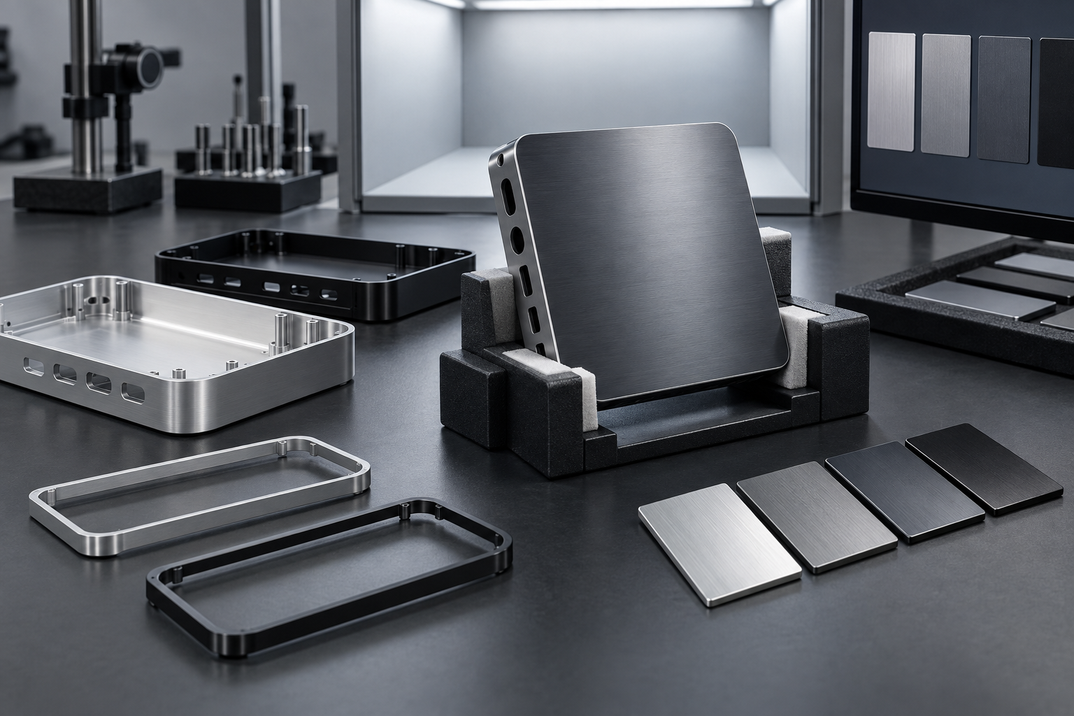
Approve the finish on production-representative parts, then control the variables that created it. Alloy lot, extrusion direction, machining pattern, blasting or brushing, etching, anodizing load, dye, sealing, part orientation and inspection light can all change what the customer sees. The released standard should tell manufacturing and quality teams how to make the same decision without relying on memory.
Use this five-step housing finish release
- Define the product experience: map visible faces, touch points, adjacent matching parts, environment and service life.
- Protect the interfaces: mark grounding, thermal, adhesive, sealing, thread, display and tight-fit surfaces.
- Build the finish stack: control alloy, machining or forming, mechanical texture, pretreatment, coating, color and gloss.
- Approve production-like assemblies: compare complete housings under stated light, angle, distance and installed orientation.
- Release controls: preserve samples, measurement settings, lot traceability, packaging and change approval.
Translate product appearance into engineering requirements
Consumer electronics housings are touched, viewed at close range and compared with neighboring parts. A technically sound coating can still be rejected if the grain direction changes across an assembly, a dark frame looks warmer than the rear cover, or a rack mark appears beside a port. Begin with the product experience, then convert it into manufacturing and inspection controls.
Define the use environment, expected handling, cleaning agents, abrasion points, UV exposure where relevant, assembly method and service life. Identify surfaces used for RF grounding, heat transfer, adhesive bonding, electrical isolation, labeling and sealing. These functions determine where coating is required, where it is prohibited and which tests belong in the project specification.
The aluminum electronics housing review should include the enclosure, bezels, buttons, covers and adjacent trim as one visual system. Evaluating each part in isolation can miss assembly-level color, gap, flushness and texture problems.
Create a finish requirement matrix before selecting a process
| Requirement | What to define | Why it matters | Verification |
|---|---|---|---|
| Visual character | Color family, lightness, gloss, texture and directional lay | Creates the intended product appearance | Approved samples plus controlled visual appraisal |
| Cosmetic zones | Primary, secondary, hidden and permitted contact areas | Applies effort where the user can see it | Drawing map and zone-specific defect rules |
| Functional interfaces | Grounding, thermal, adhesive, sealing, thread and fit surfaces | Finish can alter contact, dimensions or bonding | Masking map and interface tests |
| Durability | Wear, chemical, corrosion and handling exposures | Appearance must survive intended use | Project-specific test method and acceptance limit |
| Part matching | Reference part, viewing orientation and grouping rules | Small differences become visible side by side | Assembly-level comparison and instrument data where suitable |
| Production control | Alloy, pretreatment, process window, lot and change approval | Keeps later builds comparable to approval | Traveler, lot record, first article and change review |
Do not start with a coating catalog and force the product around it. Compare candidate finishes against the matrix. Anodizing, powder coating, wet paint, conversion coating and an unfinished mechanical texture serve different combinations of appearance, durability, conductivity and geometry.
Map primary, secondary and hidden cosmetic surfaces
Mark the cosmetic zones directly on controlled drawings or a model-based finish map. Primary surfaces are normally seen during use; secondary surfaces appear during setup or servicing; hidden surfaces remain out of view after assembly. These labels are project definitions, not universal A, B or C classes.
Include edges, chamfers, radii, display openings, port walls and the transition between exterior and interior faces. Define whether a defect crossing a silhouette edge receives stricter treatment. Show excluded areas for clamps, racks, electrical contacts, masking transitions or sacrificial tooling tabs.
A zone should carry an inspection rule, not only a color. For each defect type, state whether it is prohibited or allowed under a project-defined size, contrast, count, spacing and cluster rule. “No defects” and “cosmetic quality” leave too much interpretation for repeat production.
Control the substrate and manufacturing route
Anodized appearance begins with the aluminum below the coating. Alloy and temper, billet or sheet source, extrusion structure, grain direction, welding, heat treatment and local machining can affect shade and texture. Parts processed together can still look different when their substrates or prior operations differ.
The Aluminum Anodizers Council guidance on specifying anodized finishes explains that alloy and temper affect both performance and appearance, and that anodic oxide follows the underlying surface texture rather than hiding it. Keep visible matching parts on an agreed material and process route where practical, and require review before a source or alloy change.
For a CNC-machined aluminum housing, define acceptable tool-path direction, blend locations, setup transitions and deburring appearance. For an extruded or formed housing, address longitudinal structure, die lines, stretch marks and local deformation. Mechanical preparation can reduce some variation but cannot be assumed to erase every substrate condition.
Specify texture before color
Texture changes how color and gloss are perceived. Fine blasting may create a diffuse matte appearance; brushing creates directional lay; polishing emphasizes reflection and can reveal waviness. The same dye or coating color can look different when applied over different textures.
Describe the process sequence, treated faces and direction relative to a stable datum. A brushed enclosure needs a grain arrow and a rule for aligning neighboring components. A blasted housing needs controls for media condition, contamination, access shadows and edge exposure. Coordinate these choices with brushed aluminum finishing and the actual geometry.
ASME B46.1-2019 (R2026) defines surface texture and its roughness, waviness and lay constituents. A roughness value can support functional or process control, but it does not fully specify visible grain, reflectance, an isolated scratch or overall cosmetic uniformity. Use texture measurements and appearance standards for their separate purposes.
Write a complete anodizing callout
When anodizing is selected, the drawing should identify the governing specification and finish type, alloy and temper, pretreatment, color method and target, coating requirements, sealing where applicable, significant surfaces, measurement locations, masking, contact points, appearance criteria and required tests. The released sample should be traceable to the defined process.
ASTM B580-25 covers porous anodic oxide coatings on aluminum where appearance, abrasion resistance, electrical properties and corrosion protection matter. Its categories do not replace every other anodizing specification, so confirm the applicable project standard rather than citing one document as universal.
Discuss the desired result with the anodized aluminum supply chain before freezing the drawing. A descriptive color name is not a measurable target, and one sample coupon may not represent a large machined housing with edges, recesses and mixed surface orientations.
Define color by reference, method and viewing conditions
Color acceptance can combine visual limit samples with instrumental measurements. The contract should identify the master reference, acceptable production range, instrument geometry, illuminant, observer setting, aperture, measurement locations, number of readings, calculation method and how data relate to visual acceptance.
ASTM D2244-25 covers calculations for small color differences from instrumentally measured coordinates. It requires purchaser and seller agreement on the permissible tolerance and calculation procedure, and it notes that proximity, gloss and texture can affect commercial acceptability. Do not publish a generic ΔE limit and assume it fits every anodized color, texture, shape and product position.
ASTM D1729-22 describes controlled visual appraisal of color differences for diffusely illuminated opaque materials. Its scope also notes that metallic or pearlescent effects may need directional illumination. Anodized aluminum is directionally reflective, so the project should specify the viewing angle and part orientation that represent normal use.
Keep gloss requirements within the method’s scope
Gloss contributes to perceived quality, but geometry and texture can prevent reliable readings. State the gloss method, measurement angle, instrument aperture, location and reference condition. A curved bezel, narrow rib or heavily textured surface may not support the same method used on a flat coated panel.
ASTM D523-14(2018) covers specular gloss measurement for nonmetallic specimens at defined geometries. Its scope and specimen conditions must be checked before applying it to brushed, rough, narrow or curved anodized areas. When instrumental gloss is unsuitable, use a controlled visual reference and document the limitation.
Color and gloss should be evaluated together. A part can meet a color-coordinate tolerance yet appear different because its gloss, texture or orientation changes. Assembly approval should consider the combined appearance seen by the user.
Use consistent defect language and project-specific limits
Define scratches, scuffs, pits, dents, nicks, stains, water marks, tool lines, chatter, blast shadows, brush discontinuities, coating burns and color bands before setting acceptance limits. Teams cannot consistently inspect a condition they name differently.
ISO 8785:1998 establishes terms, definitions and parameters for surface imperfections and remained current after its 2025 review. It can support a shared vocabulary, but the product team still needs photographs, zones and numerical or visual limits suited to its housing.
| Condition | Possible source | Why a generic rule fails | Useful control |
|---|---|---|---|
| Scratch or scuff | Chips, handling, cleaning or packaging | Visibility changes with direction and contrast | Zone, size, count, spacing and approved limit sample |
| Color band or shade shift | Material, etch, load position, dye or sealing | A single reading may miss a local pattern | Measurement map plus whole-part visual review |
| Tool or brush transition | Setup change, blend or access limit | It may be intentional in one location and unacceptable in another | Permitted transition map and direction reference |
| Pit, dent or nick | Substrate, impact or rack handling | Functional and cosmetic consequences differ by location | Defect definition, edge rule and zone limit |
| Stain or residue | Cleaner, rinse, fingerprints or packaging | Some marks are removable and others indicate process damage | Approved cleaning method and final inspection state |
Plan rack marks, masks and contact points early
Anodizing needs electrical contact, and the contact location can leave a rack witness. Masking can leave an edge, color transition or adhesive residue. Put these unavoidable process features in hidden or designated zones before tooling and fixtures are committed.
Draw the maximum permitted contact area and identify whether the mark may be bare, recessed or later covered by assembly. Check that the location can carry the process current without damaging a delicate edge. Coordinate masks around threads, grounding pads, press fits, adhesive surfaces and thermal interfaces.
Do not place an appearance requirement and a mandatory contact point on the same small surface without defining priority. A practical design and finish review can resolve these conflicts before the first cosmetic build.
Protect dimensional and functional interfaces
Surface treatment can change dimensions and surface behavior. State whether dimensions are verified before or after finishing, and identify features whose fit, electrical resistance, thermal contact, sealing or adhesive performance depends on their final condition. Avoid applying a general “mask all threads” rule when the assembly needs a specific finished or unfinished interface.
Measure critical features in the same state in which the customer receives them. If a bore is masked, define the mask boundary and permitted transition. If a sealing land is finished, validate the coating, texture and flatness requirements together. If a grounding feature must remain conductive, verify the assembled electrical path rather than relying on visual inspection.
Maintain a clear relationship between aluminum surface finishing, dimensional inspection and assembly tests. A cosmetic rework that removes coating or rounds a sharp visual edge can also change function.
Inspect under a controlled visual method
A repeatable cosmetic inspection states the light source, illuminance or booth condition, background, viewing distance, viewing angle, part orientation, inspection time, cleanliness state and whether magnification or raking light is used. Choose conditions that reveal defects relevant to normal use without creating an artificial standard that no user will experience.
Approved limit samples should show the center of the target and the acceptable boundaries, not only one ideal “golden sample.” Protect samples from fading, contamination and handling damage; identify revision, finish route and approval date. Replace them through a controlled process when they no longer represent the requirement.
Use trained inspectors and connect results to controlled quality and inspection records. Record disputed conditions with the actual lighting and orientation. Photographs help communicate location but usually do not reproduce color and gloss accurately enough to replace physical samples or properly controlled measurement.
Match complete assemblies, not isolated parts
Adjacent housings, bezels, buttons and trim amplify small differences. Define which components must match, how close they appear in normal use and whether they should come from coordinated material and finishing lots. Preserve orientation when directional textures meet across a seam.
Build an assembly-level appearance review into first article and change validation. Check color, gloss, grain direction, gap, flushness, edge highlights, port transitions and logo or marking contrast. A part that passes alone may still fail the product presentation.
For mixed processes, do not assume anodized extrusion, machined plate and coated sheet can share one identical visual target. Use physical development samples to establish an achievable family resemblance or deliberately design a contrast.
Validate durability against real use
Cosmetic approval at the factory is only the starting condition. Identify the contacts and exposures the housing will experience: hands, sleeves, bags, desk abrasion, cleaning fluids, sunscreen, sweat, indoor light, outdoor light, temperature cycles or service tools. Select test methods that represent the intended product and finish.
Write the conditioning, load, number of cycles, contact material, evaluation method and acceptance rule. A test name without these conditions does not define severity. After exposure, inspect appearance and any related function such as adhesion, corrosion protection, electrical contact or label legibility.
Do not convert a supplier’s generic coating performance into a finished-product guarantee. Geometry, pretreatment, colorant, sealing, thickness, assembly stress and use environment can change the result. Validate representative housings made through the released route.
Prevent handling and packaging from becoming the final defect source
Cosmetic controls must continue after final inspection. Use clean gloves, non-marring fixtures, separated trays and compatible protective materials. Prevent part-to-part contact and movement. Define contact zones so foam, film, paper or adhesive does not imprint a visible face or leave residue.
Inspect after representative packing and transport, not only before it. Check scratches, scuffs, dents, moisture stains, color transfer, residue and edge damage. The package passes when the housing still meets its released appearance and functional requirements.
A practical surface-finish release workflow
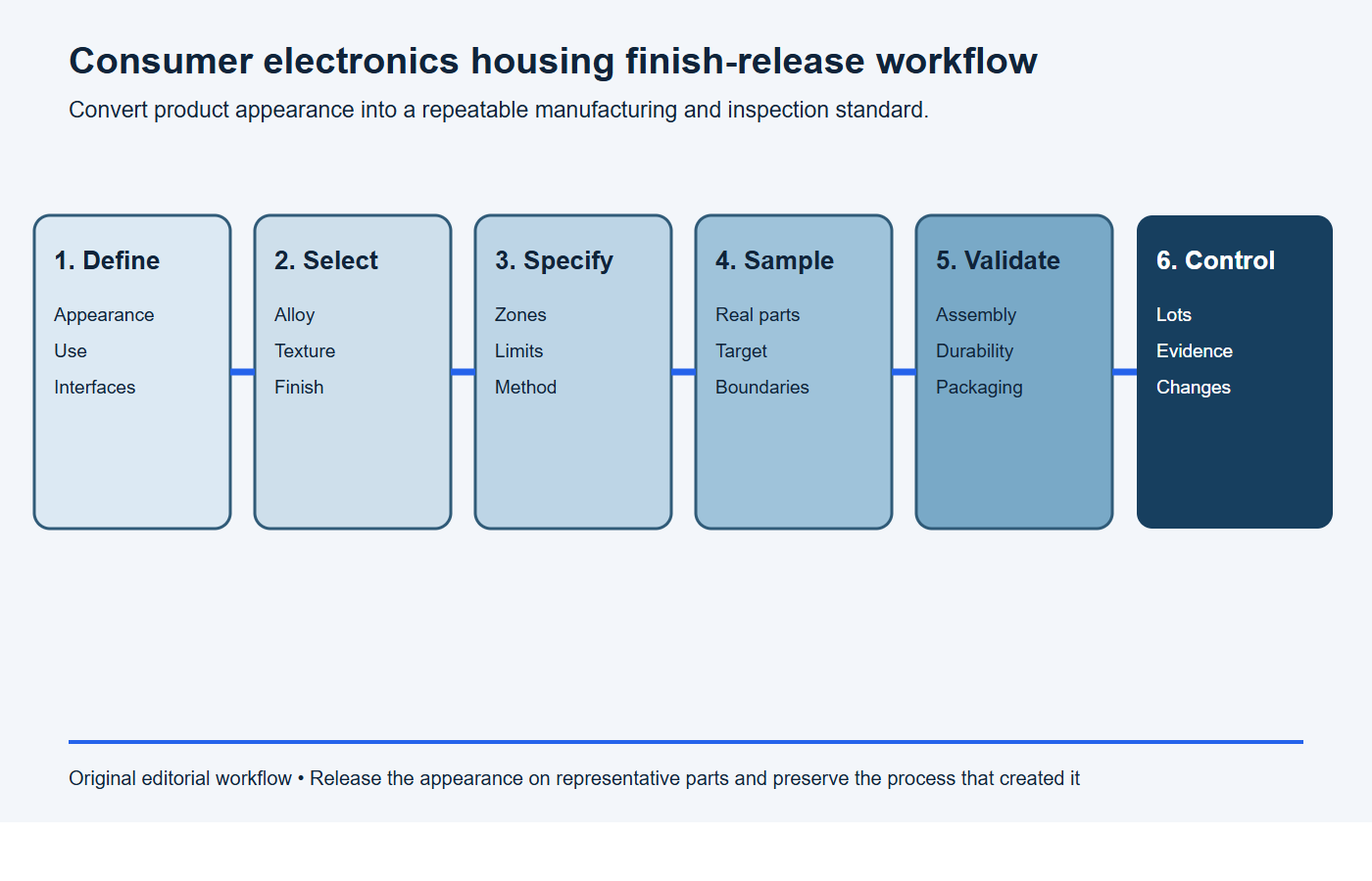
- Define the product experience. Record visible zones, touch points, adjacent parts, environment and functional interfaces.
- Select the material and route. Align alloy, product form, machining, texture, pretreatment and final coating.
- Create the specification. Add color, gloss, defects, masks, contact points, dimensions, tests and inspection conditions.
- Develop representative samples. Use production-like geometry and compare candidate finishes under the intended viewing method.
- Validate the complete product. Inspect assembled appearance, durability, interfaces and packaged transport condition.
- Release and control. Preserve references, lot traceability, work instructions, first article evidence and change approval.
Stop conditions: the housing finish is not ready
- The requirement is only “premium matte,” “black anodize” or a digital rendering without a controlled finish stack.
- Matching housings, bezels, buttons and covers use different alloy lots or surface routes without an assembly-level approval plan.
- Grounding, thermal, adhesive, sealing, thread or display interfaces conflict with coating and masking.
- Color, gloss and defects have no physical limit samples, viewing conditions or suitable instrumental method.
- The production-like sample has not passed handling, cleaning, durability, assembly and packaging validation.
Copy-ready consumer electronics finish request
Please develop the finish for housing [part/revision] and matching group [parts]. Use alloy/product form [requirement] and the intended machining or forming route. Define mechanical texture, grain direction, pretreatment, coating/anodizing, color, gloss, cosmetic zones, allowed defects, masks, rack contacts and post-finish dimensions. Produce representative assembled samples and propose visual and instrumental acceptance under [lighting, distance, angle and orientation]. Include durability, interface, cleaning, handling and packaging validation plus lot and process-change controls.
Surface-finish specification checklist
- housing drawing, 3D model and installed orientation;
- primary, secondary, hidden and excluded surface map;
- alloy, temper, product form and approved source-change rule;
- machining, deburring, blasting, brushing or polishing sequence;
- finish specification, color method, sealing and performance requirements;
- grain direction and adjacent-part matching groups;
- rack, clamp, mask, grounding, thermal and adhesive locations;
- dimensions and interfaces inspected in final condition;
- defect vocabulary, zone limits and cluster rules;
- lighting, distance, angle, orientation and inspection time;
- approved target and boundary samples with revision control;
- instrument geometry, settings, measurement map and calculation method;
- durability, assembly and packaging validation;
- lot traceability, first article and process-change approval.
Frequently asked questions
Is anodizing the best finish for every consumer electronics aluminum housing?
No. Anodizing can provide a durable metallic appearance, but the right choice depends on color range, texture, wear, corrosion, electrical interfaces, geometry and matching requirements. Compare it with coating and unfinished mechanical options against a written requirement matrix.
Can a drawing specify only “black anodize, cosmetic”?
That callout is incomplete for a controlled appearance. Add the governing finish specification, alloy and pretreatment, target reference, acceptable range, significant surfaces, mask and rack locations, inspection conditions and required performance tests.
Does a low Ra guarantee a premium-looking housing?
No. Ra describes one aspect of measured surface texture. Visible appearance also depends on waviness, lay, machining pattern, mechanical preparation, coating, color, gloss, isolated defects, part orientation and lighting.
Should color acceptance use visual inspection or a colorimeter?
Many projects benefit from both. Instrumental data improve repeatability when geometry and surface allow reliable measurement; controlled visual appraisal captures directional appearance and assembly context. Define how the two methods resolve disagreement.
How should matching parts be controlled?
Identify the matching group, installed orientation and master reference. Coordinate material and finishing lots where practical, measure defined locations, and approve the parts as an assembly under controlled lighting.
When should the finish specification be frozen?
Freeze it after production-representative samples demonstrate appearance, interfaces, durability, assembly and packaging. An ideal flat coupon alone is insufficient for a housing with corners, ports, recesses and mixed orientations.
Request a consumer electronics housing finish review
BAOSONG can review the housing drawing, cosmetic map, machining route, finish callout, matching groups, inspection method and packaging inputs as one controlled requirement. Send the 2D drawing, 3D model, target samples and application conditions through contact us for project-specific feedback.
Recommended Downloads for Aluminum Surface Finish Control
Use these BAOSONG references to select a finish, define cosmetic acceptance and prepare a production-ready requirement.
- Aluminum Surface Finish Selection Guide (PDF)
- Anodizing Guide: Color, Masking & Cosmetic Standards (PDF)
- Powder Coating, Brushing & Polishing Guide (PDF)
- Surface Finish Comparison Chart (editable Excel)
- Cosmetic Surface Requirement Template (editable Excel)
- Appearance Requirement Template (editable Excel)
Need help matching color, masking, gloss or cosmetic zones to your drawing? Contact BAOSONG engineering support.
