
Quick answer: what should an aluminum surface-finish callout include?
An aluminum surface-finish callout should identify the applicable surfaces, the required surface texture or preparation, the final treatment or coating, and the acceptance method. State the governing standard and revision, measurement units, critical parameters, grain or lay direction, color or appearance reference, coating thickness where relevant, and any masking or contact locations.
Separate functional texture from cosmetic appearance. A roughness value such as Ra can control a seal face or bearing surface, but it does not define anodized color, gloss, directional brushing, isolated tool marks or visual uniformity. Cosmetic requirements need classified surfaces, approved physical samples and controlled viewing conditions.
Also state whether dimensions apply before or after finishing and which features must remain conductive, uncoated or free of buildup. The best drawing communicates the performance outcome and inspection evidence while allowing the manufacturer to choose a capable process unless a specific manufacturing method is essential.

Use this five-step drawing review
- Classify every surface: separate functional, primary cosmetic, secondary cosmetic, hidden and masked areas.
- Choose the control: assign texture, mechanical preparation, chemical preparation and final coating only where needed.
- Write the finished state: state standards, editions, units, lay, color, gloss, thickness and post-finish dimensions.
- Define acceptance: specify measurement conditions, physical samples, viewing conditions and inspection records.
- Check manufacturability: review access, sequencing, alloy response, masking, racking and packaging before release.
“Surface finish” can mean four different requirements
Many drawing disputes begin because the phrase “surface finish” is used for several different characteristics. The designer may mean machining texture, visual appearance, a chemical pretreatment or a protective coating. The supplier may interpret the same note in only one of those ways.
- Surface texture: roughness, waviness, lay and related profile characteristics.
- Mechanical appearance: as-machined, brushed, polished, tumbled or blasted preparation.
- Chemical preparation: cleaning, etching, brightening or conversion treatment.
- Final coating: anodizing, powder coating, wet paint or another specified finish system.
Write requirements for each layer that matters. “Black finish” does not define whether the part is anodized or painted. “Satin” does not define direction, gloss or acceptable variation. “Ra 1.6” does not state units, maximum versus range, applicable surface or measurement method.
Use a drawing hierarchy that keeps requirements traceable
A clear product definition normally uses three levels. The drawing points to the relevant faces and lists short controlling notes. A referenced finish specification contains process and inspection detail. Approved samples or color standards provide appearance evidence that cannot be captured completely in text.
Keep each requirement in one controlling location. If the title block says one general roughness, a surface symbol says another and a finish note implies a third, the supplier must ask which one governs. Establish precedence in the drawing or company drafting standard and use revision-controlled references that are supplied with the RFQ.
For model-based definition, the same principle applies. Product manufacturing information must remain associated with the correct model surface and be available in a human-reviewable output. Do not assume that a color applied in CAD is a controlled finish specification.
Classify functional and cosmetic surfaces first
Start by dividing the part according to function and visibility. A sealing land, sliding bore, electrical ground and customer-facing bezel need different controls. Applying the tightest texture or cosmetic requirement to every surface increases processing and inspection without improving the product.
| Surface class | Typical purpose | Drawing information | Acceptance evidence |
|---|---|---|---|
| Functional texture | Seal, bearing, sliding, bonding or optical interface | Texture parameter, limit, units, lay and measurement conditions | Calibrated measurement at defined locations |
| Primary cosmetic | Customer-facing or adjacent visible surface | Finish route, appearance class, grain direction and color reference | Approved limit samples under controlled viewing |
| Secondary cosmetic | Visible during installation or service | Allowed defect class and finish continuity | Defined visual inspection |
| Non-cosmetic | Hidden surface without special appearance duty | General manufacturing and coating requirement | Normal workmanship criteria |
| Mask or contact | Thread, fit, ground, rack contact or adhesive area | Boundary, allowable transition and residue requirement | Coverage and location check |
Use lettered or numbered surface zones with leaders, section views or a finish map. Define whether edges belong to an adjacent cosmetic face. On assemblies, identify which faces must match one another and the orientation in which they are viewed.
Choose one surface-texture standard and state its edition
For ASME-based drawings, ASME Y14.36 establishes methods for indicating surface-texture controls with symbols. The standard expressly addresses the indication method and does not prescribe how the texture must be produced or measured. ASME B46.1 defines surface texture, its constituents and parameters used for specification and measurement.
For ISO-based technical product documentation, ISO 21920-1:2021 specifies rules for indicating profile surface texture with graphical symbols and replaced the withdrawn ISO 1302:2002. Existing drawings may still contractually invoke an older edition, so do not silently reinterpret them; resolve the governing requirement through drawing control.
Do not mix symbol syntax or default rules from different systems on the same drawing without an explicit company convention. State the units and standard edition, and make sure manufacturing and inspection teams have access to the referenced documents.
Specify the parameter, limit and measurement conditions
Ra is widely used, but it is only one arithmetic average parameter. Rz and other parameters describe different aspects of a profile. One cannot be converted reliably into another with a universal ratio. Select the parameter because it relates to function or an established process-control need, not because it is the organization’s default.
A usable texture requirement identifies:
- parameter name and whether the value is a maximum, minimum or bounded range;
- units, normally stated consistently across the drawing;
- applicable surfaces and sampling locations;
- filter, cutoff or nesting-index conditions required by the governing standard;
- evaluation length and number of measurements when project-specific control is needed;
- measurement direction relative to lay;
- special treatment of short surfaces, curvature, edges or interrupted profiles.
Instrument access matters. A stylus cannot obtain a representative trace on every narrow groove, small radius or deep pocket. If a critical area is inaccessible, agree a representative witness coupon, replica method or alternative measurement approach before production. A coupon is useful only when its material and process exposure represent the part.
State lay direction where function or appearance depends on it
Lay is the predominant direction of the surface pattern. On a sealing interface, orientation may affect leakage or wear. On brushed aluminum, it controls reflected light and whether adjacent panels appear matched. A roughness value without lay can permit surfaces that measure similarly but behave or look different.
Use the graphical convention defined by the chosen drawing standard and add a datum-related grain arrow for cosmetic brushed faces when that makes the assembly intent clearer. Relate direction to the part, not to a sheet orientation that may be rotated. For symmetric components, add an orientation feature or packaging control so the visible direction is preserved during assembly.
For a brushed aluminum finish, include the relevant direction and sample requirements directly in the RFQ package. Do not rely on an unpublished reference to carry a controlling production requirement.
Write as-machined requirements around function
An as-machined note should define the allowable texture and workmanship on the surfaces it covers. It should not require cosmetic uniformity implicitly. Milling passes, turning feed marks and tool entry or exit can be acceptable while still producing directional differences visible under raking light.
For aluminum CNC machining, mark seal faces, bearing seats and sliding interfaces individually. Keep general texture requirements realistic for the manufacturing route. If all visible tool paths must run in one direction or circular witness marks are prohibited, state that as appearance information and agree how it will be judged. The broader CNC machining plan should carry the same revision and surface identifiers.
Do not ask a secondary coating to hide deep tool marks, dents or rework. Anodizing is conformal and powder coating has limited leveling. The incoming surface condition remains part of the finished result.
Specify mechanical preparation as a controlled layer
Brushing, polishing, tumbling and blasting are preparation processes, not complete protection systems. A drawing should define where the preparation applies, directional requirements, protected details, transition zones and the approved appearance. If the method itself is mandatory, name it and reference the controlled process specification.
The Aluminum Association Designation System for Aluminum Finishes organizes mechanical finishes, chemical finishes and coatings so a complete sequence can be communicated. The Aluminum Anodizers Council summary also notes that customer and finisher should determine the exact process through sampling or discussion for appearance categories.
Abrasive grit alone is not an appearance standard. Abrasive type, manufacturer, wear, pressure, speed, passes and substrate all influence the result. Approve the finished production route on representative parts and then control the process window.
Make an anodizing callout complete
An anodizing note should identify the governing standard and edition, anodizing category or type, color class, required coating characteristic such as thickness where applicable, sealing requirement, significant surfaces, electrical-contact locations and post-treatment inspection. State any restrictions driven by electrical conductivity, fatigue, wear, bonding or dimensions.
ASTM B580-25 covers porous anodic oxide coatings where appearance, abrasion resistance, electrical properties and corrosion protection are important. Its scope and coating categories do not replace every other anodizing specification, so select the controlling document and requirements that match the actual application.
The Aluminum Anodizers Council’s specification bulletin explains that alloy, temper, mechanical finish and chemical preparation affect the anodized appearance. A color name alone is therefore insufficient. Link the requirement to material, pretreatment, approved sample and inspection conditions. BAOSONG’s anodized aluminum page provides service context for design review.
Define conversion coating, paint or powder as a system
For conversion coating, state the governing specification, class or type, required performance and whether the surface must remain electrically conductive or support later bonding or painting. Mark excluded areas and define cleaning or handling restrictions. Avoid substituting one chemistry for another when the qualification basis is material to the project.
For powder coating or wet paint, specify the coating system rather than color alone. Include substrate preparation, primer if required, resin or product qualification, color reference, gloss range, thickness range, cure or performance requirement, significant surfaces, masking and allowed rack marks. A color code does not define texture, gloss or batch-to-batch tolerance by itself.
Coordinate these notes with surface finishing and metal fabrication. Welds, sharp edges, crevices and mixed substrates can require different preparation or show-through controls.
State whether dimensions apply before or after finishing
Coatings and conversion processes interact with dimensions in different ways. A deposited organic coating adds material; anodizing converts aluminum at the surface and also produces outward growth. Stripping and reprocessing can remove more substrate. The effect depends on the specification, process and geometry, so do not use a generic allowance.
The drawing should identify the final dimensional condition and the surfaces included in any coating-thickness requirement. For fits, threads, bearing bores, seal grooves and grounding areas, decide whether to mask, compensate the manufacturing dimension, or machine after finishing. State the chosen route rather than leaving the supplier to infer it.
Keep texture, size and geometric tolerances coordinated. A finish operation that rounds an edge or changes flatness can affect a functional feature even if its average roughness passes. BAOSONG’s engineering support review can evaluate these interactions before release.
Show masking, rack marks and contact points explicitly
Finishing requires handling and, for many processes, electrical contact or physical support. These locations may have missing coating, witness marks or a transition boundary. Put them on non-critical surfaces where practical and define the permitted zone on the drawing.
Mark threads, precision bores, electrical grounds, adhesive areas, thermal interfaces and sealing faces that require masking or special control. Define whether overspray, edge feathering, plugged holes, masking residue or coating bridges are acceptable. When a mask boundary is visually exposed, add a location tolerance or approved appearance sample.
Do not write “mask all holes” unless every hole truly has the same function. Unnecessary masking adds manual work and creates extra finish boundaries. Label only the features whose function requires it.
Use physical samples for cosmetic requirements
Color, gloss, metallic direction, texture density and isolated defects cannot always be reduced to one instrument value. Define primary and secondary cosmetic zones, viewing distance, lighting, orientation, background and viewing time. Use signed, dated physical limit samples that represent acceptable high and low boundaries.
A digital image is useful for communication but not as the controlling color or texture reference. Camera exposure, white balance, compression and displays change appearance. Small flat coupons may also fail to represent a long extrusion, curved housing, welded assembly or machined pocket.
Reference samples by controlled identifier and revision. Store a protected master and working inspection samples, and define replacement intervals or comparison methods. For adjacent components, approve them in the assembled orientation under the intended lighting and connect the acceptance record to the project’s quality controls.
Example drawing-note structures
The following structures show which fields belong in a callout. Bracketed items are project decisions, not universal values.
| Requirement | Example structure | Supporting definition |
|---|---|---|
| Functional texture | SURFACE [ID]: [PARAMETER] [MAX/RANGE] [UNITS] PER [STANDARD + EDITION]; MEASURE [DIRECTION/LOCATIONS/CONDITIONS] | Function, lay, sampling and instrument access |
| General machined texture | UNLESS OTHERWISE SPECIFIED, MACHINED SURFACES [PARAMETER/LIMIT/UNITS] PER [STANDARD] | Explicit exceptions on critical faces |
| Brushed cosmetic face | SURFACES [A]: [MECHANICAL FINISH]; GRAIN PARALLEL TO DATUM [X]; APPEARANCE PER LIMIT SAMPLE [ID/REV] | Finish boundary and viewing conditions |
| Anodizing | ANODIZE PER [SPEC/EDITION], [TYPE/CLASS], [COLOR], [COATING REQUIREMENT]; SEAL [IF APPLICABLE]; MASK SURFACES [B] | Alloy, pretreatment, contact zone and inspection |
| Powder coating | PRETREAT AND POWDER COAT PER [SPEC]; [PRODUCT/RESIN], COLOR [REF], GLOSS [RANGE], THICKNESS [RANGE]; MASK [C] | Performance tests, rack area and appearance class |
| Cosmetic inspection | SURFACES [A] PER LIMIT SAMPLES [IDs]; INSPECT AT [DISTANCE], [LIGHTING], [ORIENTATION], [TIME] | Defect classes and assembled matching |
Common drawing mistakes that create finish disputes
- writing “anodize,” “black,” “satin” or “smooth” without a controlling specification;
- leaving units, parameter type or maximum-versus-range interpretation unstated;
- applying one tight roughness requirement to every machined surface;
- using Ra as the sole control for a visual brushed or blasted appearance;
- omitting grain direction, cosmetic zones or adjacent-part matching;
- specifying color without gloss, texture and a physical reference;
- failing to state the dimensional condition after coating;
- omitting mask, rack-contact and coating-transition zones;
- referencing an unavailable, conflicting or obsolete specification;
- approving a flat coupon that does not represent production material and geometry.
A drawing-to-production finish workflow
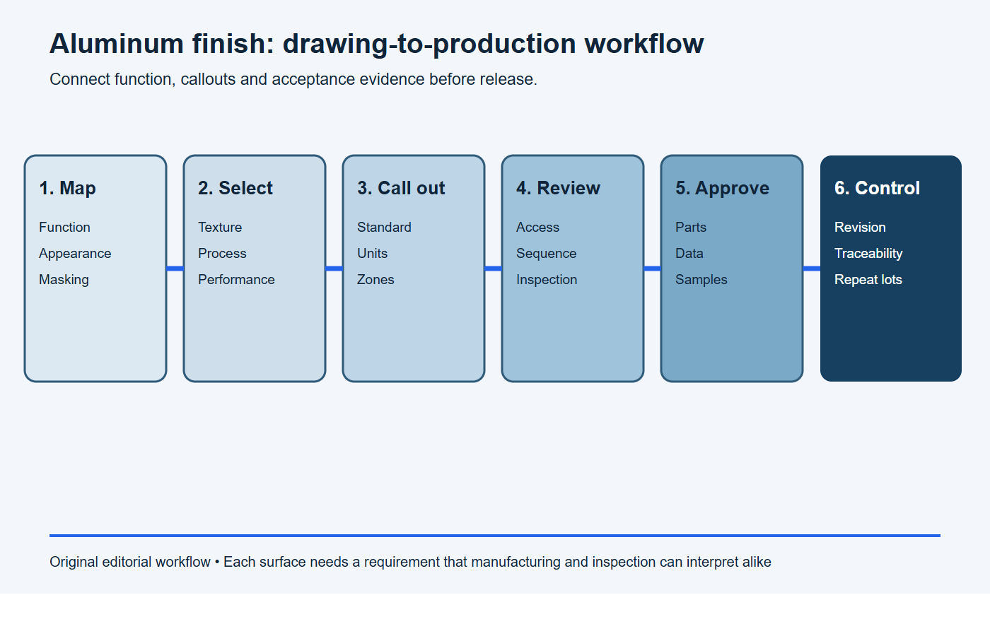
- Map surfaces: separate functional, cosmetic, hidden and masked areas.
- Select controls: choose texture parameters, finish route and performance requirements.
- Write callouts: state standards, editions, units, zones, dimensions and contact areas.
- Review feasibility: confirm process access, alloy response, inspection access and sequence.
- Approve evidence: validate representative parts, measurements and physical limit samples.
- Release and control: freeze revisions, trace lots and preserve approved samples.
Stop conditions: the finish drawing is not ready
- The note uses “standard finish,” “satin,” “black” or a roughness value without a governing definition.
- Functional texture, cosmetic appearance, preparation and final coating are mixed into one ambiguous callout.
- Units, parameter limits, lay direction, applicable surfaces or measurement conditions are missing.
- Post-finish dimensions, masking, electrical contacts, rack marks or transition zones remain undefined.
- A photograph is the only appearance reference and no controlled physical sample or viewing condition exists.
Copy-ready surface-finish drawing note review
Please review the finish callouts on part [number/revision]. For every controlled surface, identify its class and functional or cosmetic purpose. Confirm the governing texture and coating standards, editions, units, parameters, lay, preparation, coating system, color, gloss, thickness, masking and post-finish dimensions. State the inspection method, measurement locations, physical reference samples and visual conditions. List every conflict or missing requirement before quotation and production release.
Finish-specification checklist for an RFQ
- controlled 3D model and 2D drawing revision;
- aluminum alloy, temper and product form;
- governing surface-texture and coating standards with editions;
- functional surfaces, parameter limits, units, lay and measurement conditions;
- primary and secondary cosmetic surfaces;
- mechanical and chemical preparation sequence;
- final coating type, color, gloss, thickness and performance requirements;
- dimensions that apply after finishing;
- masking, rack-contact, overspray and transition zones;
- approved samples and visual inspection conditions;
- prototype and production quantity, assembly matching and packaging needs.
Send the complete package through the BAOSONG project review form. The drawing should let manufacturing and inspection reach the same interpretation before a quotation is accepted.
Frequently asked questions
Is Ra the same as surface finish?
No. Ra is one roughness parameter. Surface finish can also involve waviness, lay, visual texture, pretreatment, coating, color, gloss and defects.
Should I specify Ra for anodized aluminum?
Specify a texture parameter when function requires it, and state whether it applies before or after anodizing. For cosmetic anodizing, add the complete anodizing callout and appearance-acceptance method.
Can I put one general finish note in the title block?
Yes, for a sensible baseline that truly applies to most surfaces. Add individual callouts for critical functional, cosmetic or masked areas and define which note takes precedence.
Should dimensions apply before or after anodizing?
The drawing should state the required final condition. Review coating growth, masking and any machining after finishing for each critical fit instead of relying on an assumed allowance.
Is a RAL or color code enough for powder coating?
No. Add coating system, substrate preparation, gloss, texture, thickness or performance requirements, appearance zones, masking and an approved physical reference where matching matters.
Can a photograph define cosmetic acceptance?
A photograph can illustrate location or defect type, but it should not be the sole color or texture standard. Use controlled physical samples and written viewing conditions.
Request an aluminum drawing and finish review
BAOSONG can review surface texture, machining access, cosmetic zones, finishing sequence, dimensional effects and inspection evidence as one production definition. Share the drawing, finish specification and samples through contact us for project-specific feedback.
Recommended Downloads for Aluminum Surface Finish Control
Use these BAOSONG references to select a finish, define cosmetic acceptance and prepare a production-ready requirement.
- Aluminum Surface Finish Selection Guide (PDF)
- Anodizing Guide: Color, Masking & Cosmetic Standards (PDF)
- Powder Coating, Brushing & Polishing Guide (PDF)
- Surface Finish Comparison Chart (editable Excel)
- Cosmetic Surface Requirement Template (editable Excel)
- Appearance Requirement Template (editable Excel)
Need help matching color, masking, gloss or cosmetic zones to your drawing? Contact BAOSONG engineering support.
