
Quick answer: why do anodized aluminum parts need masking and rack-contact zones?
Anodizing is an electrolytic conversion process, so every part must make reliable electrical contact with a conductive rack or fixture. The contact area cannot develop the same continuous anodic coating as the surrounding surface and leaves a rack or contact mark. The drawing should place that mark on an approved non-cosmetic, non-sealing and non-critical area.
Masking keeps selected surfaces from receiving all or part of the anodizing process. Typical reasons include preserving electrical conductivity, protecting precision fits or threads, maintaining a bonding surface, or controlling appearance. Define the functional result and exact boundary on the drawing; let the anodizer validate a masking material and fixture compatible with the complete process.
Contact size and quantity depend on part area, alloy, anodizing type, required current, geometry and fixture stability. Do not demand an arbitrarily tiny mark that risks poor electrical contact, movement or burning. Review masking, racking, drainage, coating thickness, final dimensions and inspection together before production tooling is committed.
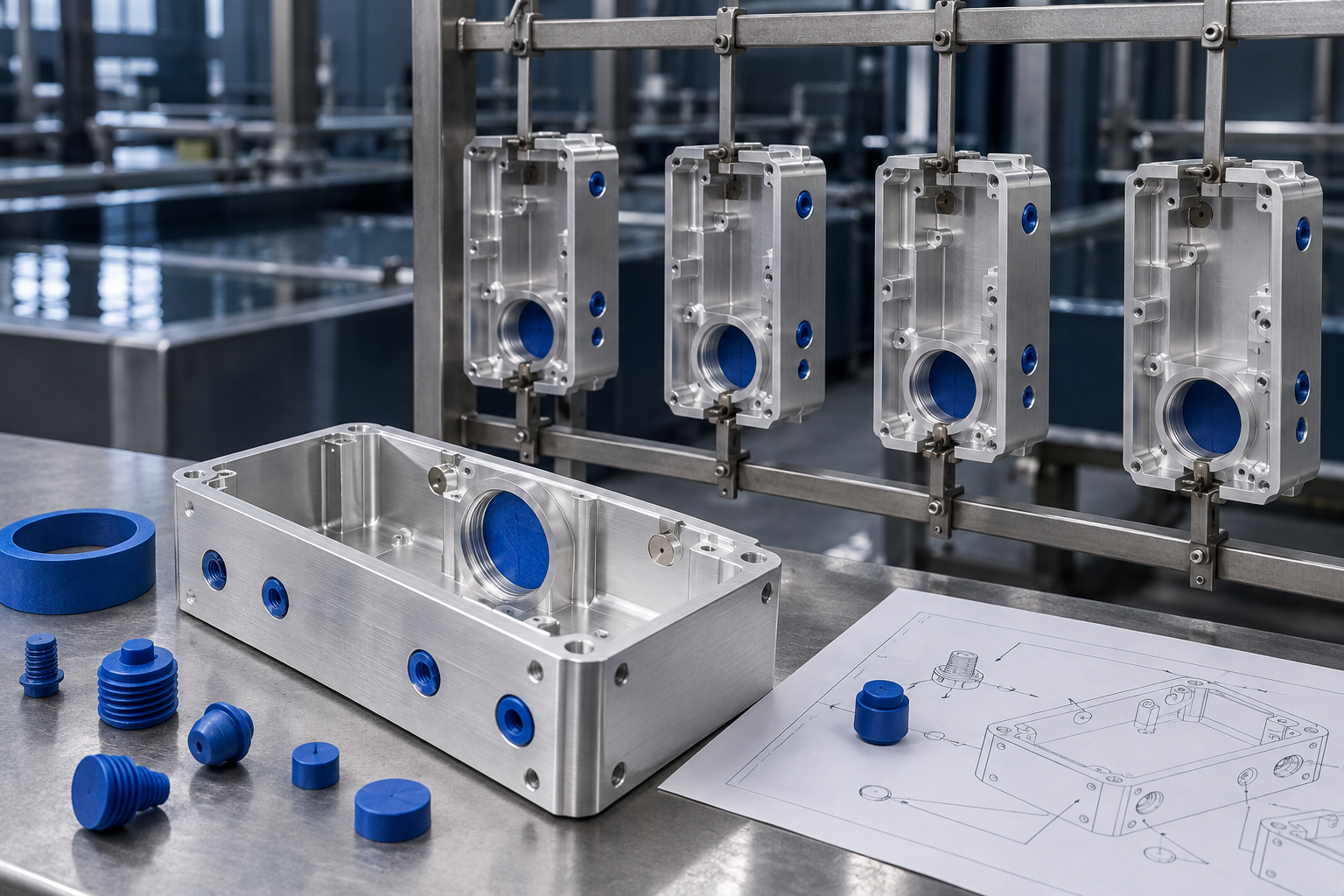
Use this five-step masking and contact review
- Map the surfaces: mark cosmetic faces, fits, threads, seals, grounds, thermal contacts and allowed witness zones.
- Define the required state: state whether each feature must be coated, bare, conductive, masked or dimensionally controlled after finish.
- Review the rack: let the anodizer confirm contact area, quantity, holding stability, current path, orientation and drainage.
- Run a representative trial: use production material, preparation, coating type, color and sealing.
- Approve and trace: record contact envelopes, mask boundaries, samples, functional tests and rack/lot identification.
Rack marks are a necessary result of electrical contact
During anodizing, the aluminum part acts as the anode in an electrical circuit. Current enters through the rack contact. Where the fixture physically touches the aluminum, the coating is interrupted or absent. A finished part with no visible contact point may simply have the point hidden, trimmed away or located inside an approved feature.
NASA’s PRC-5006 anodizing process specification states that parts must make electrical contact with the rack and that the point can leave a small void in the coating. It advises coordinating important contact locations with the responsible materials organization and vendor, or defining surfaces where contact is prohibited.
The Aluminum Anodizers Council’s guide to specifying anodized finishes compares common anodizing designation systems and shows why process type, class, coating thickness and purchaser requirements must be stated. Contact locations that matter to appearance or function belong in the controlled drawing or purchase specification.
Separate rack marks, mask boundaries and process defects
These conditions have different causes and acceptance rules:
| Condition | What it is | Normal control | Potential concern |
|---|---|---|---|
| Rack or contact mark | Local uncoated or differently coated area at the electrical fixture contact | Approved location, size envelope and count | Placed on a visible, sealing or functional surface |
| Mask boundary | Transition between processed and protected surface | Defined zone, edge quality and residue criterion | Leakage, ragged edge, excessive feathering or wrong location |
| Fixture witness | Mechanical indentation, clip line or thread contact caused by holding | Stable fixture and permitted contact zone | Distortion, burr, crack or damage outside the zone |
| Contact burn | Discolored or damaged area associated with excessive local heating or unstable contact | Sound contact, suitable area and process control | Loss of material, unacceptable appearance or reduced serviceability |
| Skip or bare patch | Unintended incomplete coating away from approved contacts or masks | Cleaning, contact, current distribution and process review | Protection or appearance does not meet the drawing |
Do not accept every bare spot as a rack mark. The production traveler or rack map should show where contact was intended. A mark elsewhere needs investigation before disposition.
Choose the contact location before finalizing the geometry
Place contact zones where they do not interfere with sealing, bearing, bonding, electrical performance or customer-visible appearance. Useful candidates may include a hidden internal boss, a non-critical hole, an extra process tab, an end allowance that will be trimmed, or a purpose-designed feature agreed with the anodizer.
Each option has trade-offs. A threaded contact can grip well but may affect the thread. An edge clip can be fast to load but leaves a visible witness. A small pointed contact may reduce the mark but can permit movement or concentrate current. A sacrificial tab needs material and a removal operation. The anodizer should select the actual rack method after reviewing part area, weight, orientation and bath sequence.
For aluminum CNC machining, add a datum-related contact zone rather than the ambiguous note “rack in hidden area.” Dimension the allowable region and show whether a dent, thread witness or bare patch is permitted within it. Coordinate the feature with workholding so the same surface is not already needed for a precision setup.
Contact area must carry current and hold the part
A good contact performs two jobs: it conducts the required current and mechanically holds the part through cleaning, etching, anodizing, rinsing, coloring and sealing. Solution flow, buoyancy, thermal expansion and rack movement can disturb a marginal grip. If contact is lost or becomes intermittent, coating nonuniformity or local damage can result.
The Aluminum Anodizers Council FAQ explains that the more current a process requires, the larger the electrical contact generally must be, and that size depends on the process and part. This is why a drawing should define a maximum acceptable zone only after feasibility review rather than forcing the smallest imaginable point.
Large or complex parts may need more than one contact to distribute current and stabilize orientation. Multiple contacts create multiple marks, so the design must balance visual placement, electrical performance and fixture security. A representative rack trial is appropriate when the location is highly constrained.
Use masking only where the function requires it
Masking is a manual and process-sensitive operation. It adds boundaries that can leak, feather or retain residue. Mask only the features that need a different final condition, and state why they need it. “Mask all holes and threads” may add work without improving the product.
Common functional reasons include:
- electrical grounding or bonding areas that must not be insulated by anodic oxide;
- precision bearing seats, dowel bores or fits affected by the final dimensional condition;
- threads whose engagement or locking method is incompatible with coating in the selected process;
- adhesive, thermal-interface or seal areas with a validated substrate requirement;
- areas reserved for welding, later machining or another surface treatment;
- cosmetic boundaries or graphics produced through selective processing.
Flat open areas can be harder to mask consistently than holes or bores because the boundary must resist the full process without a natural locating feature. Build locating grooves, shoulders or replaceable masking fixtures only after discussing repeatability and whether the added geometry affects the finished product.
Define the required condition under the mask
“No anodize” does not fully define the protected surface. Depending on when masking is applied, the area may also avoid cleaning, etching, deoxidizing, dye or sealing, or it may receive some steps and not others. State the final functional requirement rather than assuming every anodizer uses the same masking sequence.
An electrical contact may need bare aluminum, a specified chemical conversion coating, controlled resistance or another qualified treatment. A bonding area may require a particular preparation and cleanliness window. A precision fit may need only dimensional control. These outcomes require different instructions.
NASA’s MSFC-HDBK-3697 gives examples of drawing notes that mask electrical-contact areas before anodizing or painting and then apply a specified conversion coating. Use the project’s approved material and process standards rather than copying those aerospace examples into unrelated work.
Threads need a function-based decision
Whether to anodize, mask or chase a thread depends on anodizing type and thickness, thread size and class, engagement, wear, electrical needs, corrosion protection and the mating hardware. There is no universal rule that every thread should be masked.
If the thread is anodized, define the final acceptance condition and verify assembly with the actual mating component or gauge strategy. If it is masked, define how far the mask may extend beyond the thread entrance and whether incomplete first threads are acceptable. If the thread is cut or chased afterward, review the exposed aluminum, debris, corrosion protection and dimensional consequences.
Blind threaded holes also need drainage and trapped-air review. A plug can change how solution reaches the feature, while an unmasked blind cavity can retain liquid. Coordinate hole depth, venting, orientation and mask choice with the anodizer.
Protect precision bores, fits and sealing faces
Anodizing converts aluminum and produces outward growth; chemical pretreatment and any later stripping also affect the substrate. The net dimensional change depends on alloy, process and local geometry. Do not apply a universal allowance to every bore.
For a precision bore, choose among masking, machining compensation, post-anodize machining or accepting the qualified coating on the final surface. Consider wear, corrosion, fatigue, seal compatibility and whether an interrupted mask boundary is acceptable. State whether dimensions apply before or after finishing.
A seal face may require both continuous protection and controlled texture. Masking it to preserve size could leave bare aluminum that does not meet corrosion needs. Treat dimension, coating and sealing performance as one requirement. BAOSONG’s engineering support review can help expose these conflicts before release.
Grounding and bonding areas need more than a mask note
An anodized surface is electrically insulating. If the assembly needs a conductive path, show the exact contact face, boundary and final treatment. Define resistance or bonding performance where the system specification requires it, along with the measurement method and accepted hardware stack.
Consider corrosion at the exposed area. Bare aluminum under a fastener may not be an acceptable long-term solution in the service environment. A specified conversion coating, conductive washer design, sealant or protected joint may be required by the project’s electrical and corrosion-control plan.
Keep the mask boundary away from sealing edges and visible faces where practical. If the ground area is also used as a rack contact, confirm that the fixture witness remains within the allowed connection footprint and does not compromise flatness or assembly.
Racking orientation affects drainage and appearance
Part orientation influences air release, solution drainage, current distribution, color consistency and where rinse or sealing solution can collect. Deep pockets, blind cavities, narrow channels and upward-facing cups require special review. A strong electrical contact does not solve poor drainage.
Orient parts so air can escape during immersion and liquid can drain during transfer. Add holes or modify geometry only when they are functionally acceptable and validated for the process. If a surface must remain free of drain streaks or trapped-solution marks, identify it as a significant cosmetic face and discuss rack orientation before production.
Long aluminum extrusions may use end contacts or sacrificial length that is trimmed after anodizing. CNC housings may be contacted inside a bore or hidden pocket. Each route must still provide secure contact, drainage and an inspectable final boundary.
Cosmetic parts need an approved rack-mark envelope
For visible products, define both prohibited contact surfaces and one or more allowed zones. Include the maximum zone, count, mark type and any appearance limit within that zone. A physical sample is valuable because “small rack mark” does not describe contrast, indentation, exposed metal or edge shape.
Keep rack contacts away from primary cosmetic faces and adjacent-part match areas. If there is no hidden location, consider a removable tab, trim allowance, assembly cover or design feature that intentionally contains the mark. These changes should be evaluated before production tooling and cosmetic samples.
Place all controlling surface zones and acceptance criteria in the RFQ package itself. A contact location cannot be left to an unpublished reference or an informal email that is disconnected from the drawing revision.
Prevent masking leakage and residue
Masking materials must tolerate the actual cleaning, etching, anodizing, coloring, sealing and rinse sequence. Tapes, plugs, caps, liquid stop-off and custom fixtures each suit different geometries. Material compatibility, temperature, chemical resistance, adhesion and removal must be validated by the processor.
Inspection should distinguish minor transition effects allowed by the drawing from leakage that enters a protected area. Define whether the boundary may feather, how far a mask may overlap, whether adhesive or stop-off residue is permitted, and how the part may be cleaned after removal.
A masked hole can trap liquid around a poor seal. A plug installed too aggressively can deform a thin wall or damage a thread. A tape edge across a cosmetic face may leave a visible line. Use pilot parts to confirm installation, survival through the line and clean removal.
Coordinate anodizing with mechanical preparation
Blasting, brushing or polishing normally occurs before anodizing and may need to stop at a mask or contact boundary. If a rack zone is hidden only after assembly, make sure pre-anodize preparation does not create an obvious patch that extends beyond the hidden region.
NASA PRC-5006 states that required bead or grit blasting should be included in the drawing note. The broader principle is to specify the complete route. “Black anodize” alone does not define the pre-anodize texture, significant surfaces, contact zones or mask condition.
Coordinate the sequence with surface finishing and anodized aluminum requirements. Approve representative samples after masking removal and the final seal, not immediately after machining.
Write clear drawing and RFQ callouts
The following structures show what to include. Bracketed fields are project decisions and must not be treated as universal specifications. ASTM B580-25 covers porous anodic oxide coatings used where appearance, abrasion resistance, electrical properties and corrosion protection matter; it does not cover every anodizing category, so confirm applicability before using it.
| Requirement | Example structure | Complete with |
|---|---|---|
| Anodizing | ANODIZE PER [SPECIFICATION + REVISION], [TYPE/CLASS], [COLOR], [COATING REQUIREMENT] | Seal, significant surfaces, tests and final dimensions |
| Allowed contact | RACK CONTACT PERMITTED ONLY WITHIN ZONE [R]; CONTACT WITNESS SHALL REMAIN WITHIN [DEFINED ENVELOPE] | Count, indentation, exposed area and visual sample |
| Prohibited contact | NO RACK OR FIXTURE CONTACT ON SURFACES [A] | Provide a feasible allowed alternative |
| Masked feature | MASK SURFACES [B] FROM [DEFINED PROCESS STEPS] | Required final condition, boundary and residue |
| Conductive area | SURFACE [C] TO REMAIN [BARE OR SPECIFIED TREATMENT]; VERIFY [PERFORMANCE/METHOD] | Corrosion protection and assembly stack |
| Thread or bore | FEATURE [D] [MASKED/COATED/POST-MACHINED]; FINAL ACCEPTANCE [GAUGE OR DIMENSION] | Mask extension, cleanliness and coating boundary |
Inspect contacts and masks at the final condition
Inspection should confirm contact location, number and boundary against the drawing. Check for unintended bare areas, leakage, burned contacts, cracks, distortion, residue and damage outside the allowed zone. Verify functional features after masking is removed and after any final cleaning.
Coating-thickness readings should be taken only at locations suitable for the method and specification. Do not use a contact mark or mask transition as a representative coating-thickness location. For cosmetic work, inspect under the defined light, distance, orientation and physical limit sample.
Connect the rack map, masking traveler, anodize lot and inspection report to the project’s quality records. This evidence helps separate a design-location issue from a fixture, process or handling problem on repeat orders.
Common problems and first checks
| Observed condition | Investigate first | Useful evidence | Do not assume |
|---|---|---|---|
| Rack mark on a cosmetic face | Drawing zones, rack plan and fixture loading | Approved contact map and setup photo | The anodizer knew which face would be visible |
| Large or burned contact | Contact area, cleanliness, stability and current path | Rack maintenance and process record | A smaller point will solve the issue |
| Anodize inside a masked bore | Mask fit, material, installation and process survival | Mask traveler and pilot-part section | Every plug seals every chemistry |
| Ragged mask edge | Boundary geometry, adhesion and removal | Limit sample and edge inspection | Only coating thickness matters |
| Thread will not assemble | Final dimensions, coating route and mask extension | Before/after data and mating test | All threads need the same solution |
| Ground path has high resistance | Final treatment, residue, flatness and joint stack | Specified resistance test | A visually bare patch is electrically sufficient |
| Stain or rundown near a cavity | Orientation, drainage, rinsing and sealing | Rack orientation and transfer review | The rack contact caused every nearby mark |
A practical masking and racking workflow
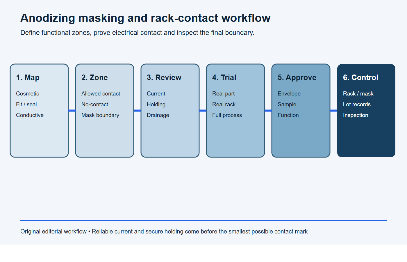
- Map: identify cosmetic, dimensional, sealing, bonding and conductive surfaces.
- Zone: define allowed and prohibited contact and masking boundaries.
- Review: confirm electrical load, fixture stability, orientation and drainage with the anodizer.
- Trial: process representative parts using the intended material and complete finish route.
- Approve: agree contact envelopes, mask boundaries, samples and functional tests.
- Control: trace racks, masks, lots, inspection and packaging through production.
Stop conditions: the masking and contact plan is not ready
- The drawing says “rack in hidden area” without a dimensioned allowed zone and prohibited surfaces.
- The required condition under each mask—bare, conductive, corrosion protected or dimensionally controlled—is unclear.
- The requested contact is too small to support current and fixture stability for the selected anodizing process.
- Threads, precision fits, seals, grounds or bonding areas have no finished-state functional test.
- Orientation, drainage, trapped air, mask leakage, residue and final packaging have not been reviewed on representative parts.
Copy-ready anodizing masking and rack request
Please review masking and rack contacts for part [number/revision], alloy/temper [requirement] and anodizing [specification/type/class/color]. Use the drawing to confirm allowed and prohibited contact zones, maximum witness envelope, count, mask boundaries and the required condition beneath each mask. Verify current path, holding stability, orientation, drainage, post-finish dimensions and functional tests for threads, fits, seals, grounds and bonding areas. Process representative samples and provide a rack map, masking record and final inspection evidence before approval.
RFQ checklist for anodizing masks and contacts
- controlled 3D model and 2D drawing revision;
- alloy, temper, product form and lot-matching needs;
- anodizing specification, revision, type, class, color and coating requirement;
- significant functional and cosmetic surfaces;
- allowed and prohibited rack-contact zones;
- maximum contact envelope, count and appearance criteria;
- features to mask and the required condition beneath each mask;
- threads, bores, fits, seals, grounds and bonding areas;
- dimensions and gauges that apply after finishing;
- pre-anodize blasting, brushing or polishing;
- part orientation, drainage and trapped-air concerns;
- pilot quantity, limit samples, inspection records and packaging.
Send the complete package through the BAOSONG project review form. A contact plan developed before production is easier to control than a cosmetic repair after anodizing.
Frequently asked questions
Can aluminum be anodized without a rack mark?
The part needs electrical contact, so some contact witness is inherent. It can often be hidden, placed in an approved feature or removed with a planned trim operation.
Should every threaded hole be masked before anodizing?
No. Decide from coating type and thickness, thread class, engagement, corrosion, wear and electrical requirements. State the final functional acceptance for each important thread.
Can rack contacts be placed inside a hole?
Sometimes, if the hole geometry, functional requirement and rack method permit reliable contact. The resulting thread, bore or surface witness must be within an approved zone.
Does masking preserve the original dimension exactly?
Not automatically. Pretreatment exposure, mask sequence, leakage, later cleaning and the boundary can affect the result. Define the final dimension and validate the route.
Why is the rack mark larger on hard anodizing?
Contact requirements depend on current demand, process, part area, geometry and fixture stability. Do not set an expected size without the anodizer’s review of the actual job.
Can a rack mark be touched up?
Touch-up may be allowed by a controlling specification for limited purposes, but it does not recreate the original anodic coating. Use only an approved method and verify appearance and function.
Request an anodizing contact and masking review
BAOSONG can review CNC geometry, contact zones, masking, dimensional effects, cosmetic requirements, anodizing and inspection as one production system. Share the drawing and finish specification through contact us for project-specific feedback.
Recommended Downloads for Aluminum Surface Finish Control
Use these BAOSONG references to select a finish, define cosmetic acceptance and prepare a production-ready requirement.
- Aluminum Surface Finish Selection Guide (PDF)
- Anodizing Guide: Color, Masking & Cosmetic Standards (PDF)
- Powder Coating, Brushing & Polishing Guide (PDF)
- Surface Finish Comparison Chart (editable Excel)
- Cosmetic Surface Requirement Template (editable Excel)
- Appearance Requirement Template (editable Excel)
Need help matching color, masking, gloss or cosmetic zones to your drawing? Contact BAOSONG engineering support.
