
Quick answer: how do internal corners, deep pockets and thin walls affect CNC machining?
These features make a CNC-milled part more sensitive to cutter diameter, tool reach, cutting force, workholding and inspection condition. Internal corners limit the cutter size that can enter a pocket. Deep pockets need longer, less rigid tools and make chip evacuation harder. Thin walls can bend during cutting or clamping, then spring toward a different shape after release.
The features also interact. A small internal radius at the bottom of a deep pocket may force a small long-reach end mill into a high-engagement corner. If that corner sits beside a thin wall, tool deflection and wall deflection can occur at the same time. A feature that is possible on one prototype may therefore need a slower and more controlled route to remain stable across production.
Good design does not mean removing every difficult feature. It means protecting the function while giving the manufacturing team enough radius, access, wall support and datum clarity to select a stable process. Treat each value in this guide as a design question rather than a universal BAOSONG capability limit.
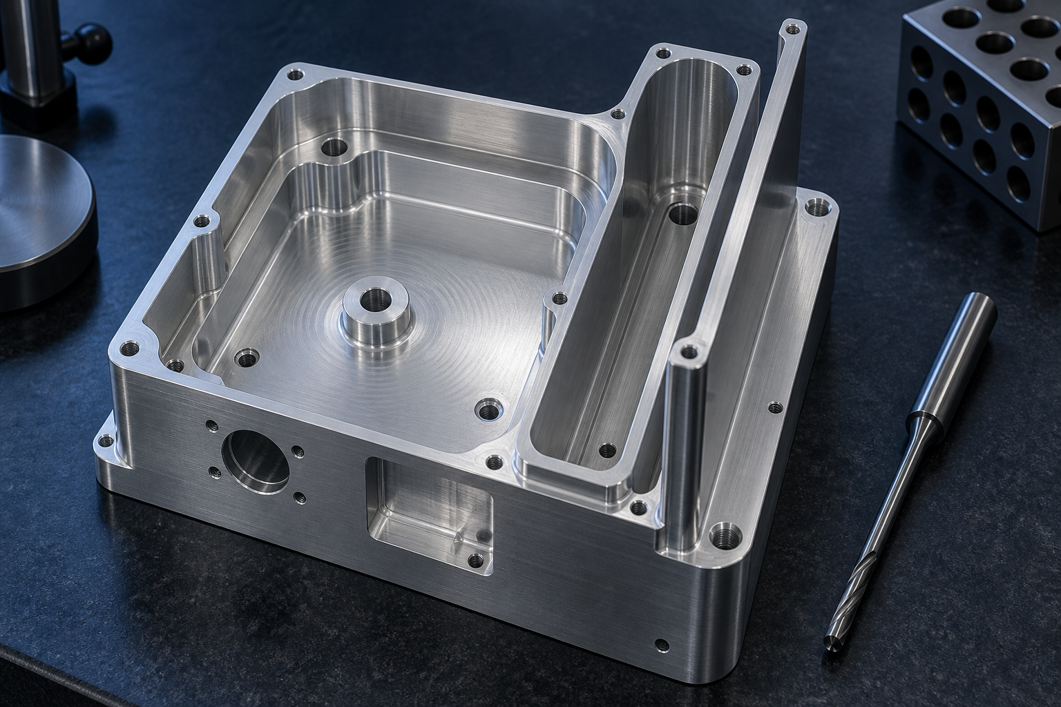
Seven-step DFM review for difficult CNC geometry
| Step | Review | Required output |
|---|---|---|
| 1 | Mark every small radius, deep region and flexible wall | Risk map tied to function |
| 2 | Replace nonfunctional sharp corners | Largest usable radius or approved relief |
| 3 | Prove tool and chip access to deep pockets | Reach, holder and rough/finish strategy |
| 4 | Evaluate wall support and released-state movement | Thickness, rib and workholding plan |
| 5 | Review compound interactions | Prioritized geometry changes |
| 6 | Assign each requirement to a process and datum | Feature-control plan |
| 7 | Define inspection and production release | First-article evidence and change controls |
Step 1: compare the three design risks
| Feature | Primary constraint | Likely production effect | First design response |
|---|---|---|---|
| Internal corner | A rotating end mill leaves a radius related to its cutting diameter and path. | A small radius can require a smaller cutter, more corner engagement and extra finishing time. | Increase the radius, add corner relief or change how the mating component locates. |
| Deep pocket | The tool, holder, spindle and coolant path must reach the cutting zone without collision. | Long reach reduces stiffness and can increase chatter, taper, recutting and cycle time. | Reduce depth, open access, use a larger corner radius or split the geometry into another part. |
| Thin wall | The workpiece may be less rigid than the cutter and fixture system. | Cutting and clamping forces can cause deflection, vibration, dimensional change or damage. | Increase thickness, reduce unsupported height, add support or plan balanced staged machining. |
The right response depends on function. A square insert may need local clearance at four corners but not four completely sharp walls. A fluid cavity may need depth but allow a generous floor radius. A lightweight enclosure may require thin walls over a broad area but permit ribs around mounting interfaces. Resolve the functional need before choosing the manufacturing workaround.
Step 2: design internal corners around function
A standard end mill rotates around a circular envelope. When it follows two perpendicular pocket walls, the tool cannot leave a zero-radius vertical inside corner. The corner radius must accommodate the cutter path. A smaller specified radius generally means a smaller end mill, while cutter length and pocket depth determine whether that tool can reach the feature with adequate rigidity.
This is different from an outside corner, which can often be profiled sharp in the horizontal plane because the cutter approaches from outside the material. It is also different from the radius between a pocket wall and floor. That floor transition depends on the tool’s end geometry and toolpath, so the drawing should distinguish a vertical corner radius from a floor radius.
Autodesk’s Fundamentals of CNC Machining explains radius milling and the use of ball-end or corner-round tools for suitable radius features. Protolabs’ machining-cost design guidance also illustrates why corner relief can preserve functional clearance while allowing a larger cutter. Supplier-specific limits in that guide should not be treated as universal limits or BAOSONG capability statements.
Choose the internal-corner solution from the assembly function
Allow the largest useful radius
If nothing square must fit into the pocket, increase the internal radius as far as the product allows. This may permit a larger and stiffer cutter, reduce the amount of material remaining for a small finishing tool and smooth the change in cutter engagement at the corner.
Add corner relief for a square mating part
A dog-bone, T-bone or another localized relief moves clearance outside the nominal square envelope. The mating component can then seat without requiring the complete vertical corner to be sharp. Select the relief orientation so it does not break a seal, reduce a load-bearing area or create an unacceptable cosmetic feature.
Change the mating part
Chamfering or rounding the mating component may be cleaner than adding four reliefs to the pocket. This is especially useful when both parts are under design control. State the assembly clearance and datum strategy so accumulated tolerances do not consume the intended fit.
Use another process only when function requires it
EDM, broaching, slotting, additive manufacture or a built-up assembly can create geometry that ordinary end milling cannot produce efficiently. Each route changes material, surface, access, cost and inspection considerations. Do not specify another process merely to preserve a CAD corner that has no functional role.
Step 3: prove access to deep pockets
A pocket is not difficult because of depth alone. The important combination includes depth, opening width, corner radius, wall taper, floor geometry, chip path, tool-holder clearance and available approach direction. A wide open cavity with a large radius can be easier than a shallower slot that only accepts a small long-reach tool.
As tool overhang increases, the cutting system becomes more compliant. Cutting forces can bend the tool, leaving wall taper or excess stock. Vibration can mark the surface and reduce tool life. Chips trapped in the cavity can be cut again, while coolant and air may not reach the active edge consistently. Extra roughing levels, rest machining, reduced engagement and separate finishing passes can control these effects, but they add programming and machine time.
Corner engagement is another issue. Research on toolpath transitions in pocket corners reports that increased engagement at sharp corners raises milling force and can reduce machining precision. Seco’s optimized-roughing guidance likewise identifies challenging corners and tall walls as cases where toolpath strategy matters. The exact cutting data remains tool-, machine-, material- and setup-specific.
Design responses for deep pockets
- Open the pocket where possible. A side opening or removable cover can improve tool access, chip evacuation and inspection.
- Increase the corner radius. A larger radius may allow a larger-diameter tool and reduce the remaining corner material.
- Separate roughing and finishing access. Leave suitable stock for a controlled finish pass instead of asking one long tool to remove all material and achieve the final wall.
- Use access from another side. Opposed machining can shorten tool reach, but the design must provide stable datums and account for the relationship between setups.
- Split the component. A base and cover or two aligned halves may be more controllable than an inaccessible monolithic cavity, provided joints, seals and assembly variation are acceptable.
- Review multi-axis access. Tilting the part or tool can avoid a collision or shorten effective reach for some surfaces. Multi-axis aluminum machining improves access in suitable cases; it does not remove cutter-radius or stiffness limits.
Step 4: control thin-wall movement
A thin wall behaves like a flexible structural member. Its response depends on thickness, unsupported height and length, material stiffness, local ribs, remaining stock, fixture contact and where the cutter applies force. Two walls with the same thickness can behave very differently if one is short and supported on three sides while the other is tall with a free edge.
During cutting, the wall may bend away from the tool. It can spring back after the cutting edge passes, leaving extra material or a wavy surface. A finishing pass can improve the result, but repeating the same force on the same flexible wall does not automatically remove the error. Clamps can also bend the part into compliance; a dimension accepted while clamped may change after release.
Autodesk Fusion’s thin-wall machining reference shows why completing one side before the other can overload a thin wall and describes machining by depth as one strategy. A 2026 open-access experimental and finite-element study of an aluminum thin wall found the greatest deflection near the free edge in its specific test geometry. That experimental value is not transferable to a different part, but the force-and-support relationship is relevant to process planning.
Design and process controls for thin-wall aluminum parts
Begin with the design. Increase wall thickness where mass and envelope permit, shorten free height, connect walls to a floor, and add ribs or local bosses around functional interfaces. Use gradual transitions so the stiff region does not create a sudden weak boundary. If cosmetic faces matter, identify them before adding a rib or relief that will remain visible.
The machining sequence should preserve support for as long as practical. A planner may rough opposing sides progressively, leave temporary stock, machine walls in depth levels, use low-force finishing passes or add sacrificial support. Soft jaws, conforming fixtures, vacuum fixtures or temporary fill can be appropriate for particular geometries, but every support method must avoid distorting the released part or blocking inspection access.
Starting material also matters. Alloy, temper and product form affect cutting behavior and residual-stress risk. Stress-relieved plate can reduce one source of movement for heavily pocketed parts, but it cannot eliminate deflection from weak geometry or poor clamping. Review T5, T6 and T651 temper conditions and aluminum alloy selection for CNC machining as separate inputs to the design.
Step 5: review how the three features compound one another
The most expensive geometry often combines constraints rather than presenting one in isolation. The schematic below follows the chain from design choice to production consequence.
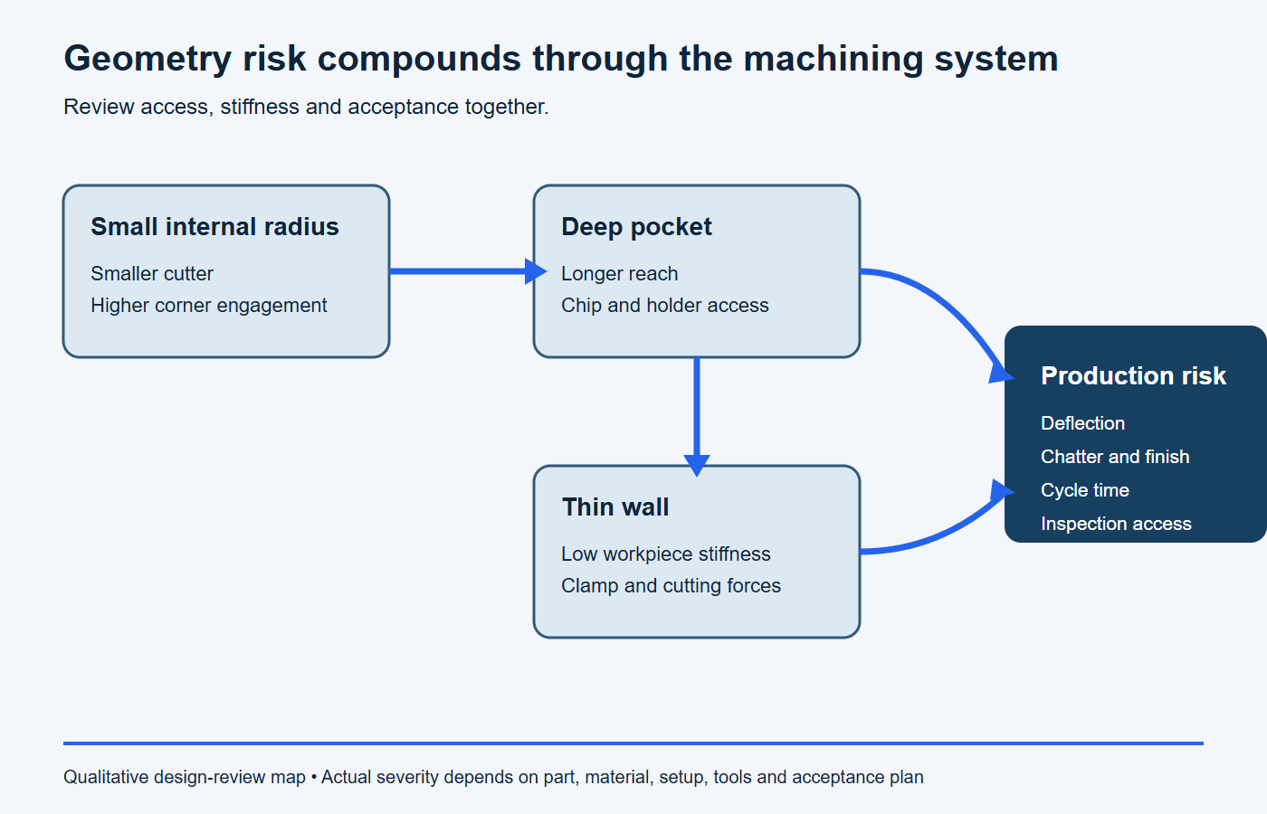
For example, reducing an internal radius can force a smaller cutter. Keeping the same pocket depth then increases reach relative to cutter size. If the cutter finishes beside a tall thin wall, both tool and workpiece can move. Specifying a tight wall profile after anodizing adds another variable because finishing and masking conditions must also be defined. Solving only the radius may therefore miss the actual production risk.
Step 6: convert the CAD model into a feature-control plan
| Drawing requirement | Questions before quotation | Possible design or process response | Acceptance question |
|---|---|---|---|
| Small vertical corner radius | What must clear or contact the corner? How deep is it and which direction is open? | Increase radius, relieve locally, modify the mating part or approve another process. | Is the radius itself inspected, or is functional clearance the actual requirement? |
| Deep cavity | Can the tool and holder reach every wall without collision? Where do chips and coolant exit? | Open a side, enlarge radii, machine from two directions or split the assembly. | Which datums control depth, wall position and relationships across setups? |
| Tall thin wall | What is the unsupported span? Can a fixture support it without changing the free state? | Thicken, shorten, rib, retain temporary support or use balanced staged passes. | Is acceptance in a free or restrained condition, and after what stabilization time? |
| Finished precision interface | Does anodizing or another finish cover the corner, wall or floor? | Define masking and separate pre-finish controls from final functional dimensions. | Which dimensions apply after surface finishing? |
This plan should connect to the drawing’s datum system and tolerance scheme. ASME’s official Y14.5-2018 (R2024) overview describes the common symbols, rules and definitions for dimensioning and tolerancing. Use the standard and edition required by the project, and avoid mixing conventions.
Step 7: inspect the released condition
Deep pockets can restrict probe access and line of sight. Small corner radii may be difficult to evaluate with the same device used for broad faces. Thin walls can move under probe force or fixture restraint. Define the characteristic, datum simulation, measuring equipment, environmental condition and sampling plan before production.
Measurement uncertainty also matters near a specification limit. NIST’s publication on uncertainty and dimensional calibrations explains that a reported result is an estimate with a range associated with measurement uncertainty. The quality and inspection plan should therefore match the feature risk rather than using one instrument and one sampling rule for every dimension.
For further tolerance planning, see Aluminum CNC Machining Tolerances: What Is Practical? It explains why machine positioning, part tolerance and verified conformance are different claims.
Production release checklist
- Every tight corner, deep pocket and thin wall has a stated functional reason.
- The supplier has reviewed cutter diameter, reach, holder clearance, chip evacuation and deburring access.
- Machining allowance, roughing, finishing and temporary support are defined for flexible regions.
- Workholding does not force the part into an acceptable shape that changes after release.
- Datums and measurement methods cover inaccessible or probe-sensitive features.
- The first article is inspected after unclamping and after the specified finish.
- Geometry, stock, fixture or sequence changes trigger documented review.
Stop conditions: the geometry is not ready for release
- A sharp internal corner remains only because it was easy to draw in CAD.
- No available cutter and holder can reach the pocket without collision or excessive overhang.
- A deep pocket has no chip, coolant, roughing or finishing plan.
- Wall thickness is specified without unsupported height, length, ribs or clamping context.
- The same region combines a small radius, long reach and flexible wall without a trial strategy.
- Acceptance is defined only while the part is clamped.
- Post-finish dimensions, masking and cosmetic faces are not identified.
Copy-ready DFM review checklist
- A revision-controlled 3D model and 2D drawing.
- The function of each tight corner, deep pocket and thin wall.
- Mating-part geometry, assembly clearance and sealing requirements.
- Alloy, temper, starting product form and permitted substitutions.
- Critical datums, geometric controls and the required drawing standard.
- Finished-state requirements, masking zones and cosmetic surfaces.
- Prototype and production quantities plus expected repeat demand.
- First-article, inspection-report and sampling expectations.
Use BAOSONG’s engineering-support resources to organize the review, or send the drawing and application requirements for a manufacturability discussion. Identify the function first; that allows the review to protect the high-value interface while relaxing geometry that does not improve performance.
Frequently asked questions
Can CNC milling make a perfectly sharp internal corner?
A rotating end mill normally leaves an internal radius. If a function requires a square fit, consider corner relief, changing the mating part, another machining process or a built-up design. The best option depends on depth, access, material and assembly requirements.
Is there a universal maximum depth-to-diameter ratio for a pocket?
No. Tool construction, diameter, holder clearance, material, engagement, coolant delivery, machine dynamics and required accuracy all affect practical reach. Review the complete pocket geometry and available approach directions instead of applying one ratio to every job.
What wall thickness is safe for aluminum CNC machining?
There is no universal safe thickness. Unsupported height and length, alloy and temper, adjacent geometry, cutting direction, workholding and tolerance matter alongside thickness. A short supported wall can behave differently from a tall free wall of the same thickness.
Does five-axis machining solve deep-pocket problems?
It can improve access and reduce effective tool reach for some faces, but it does not remove cutter-radius, collision, chip-evacuation, workpiece-stiffness or inspection constraints. Evaluate the tool direction and functional datums for the specific part.
Recommended Downloads for CNC Machining Design
Use these BAOSONG references to improve tool access, feature geometry, practical tolerances and CNC process planning before release.
- Aluminum CNC Machining Design Guide (PDF)
- CNC Milling Guide: Pockets, Walls, Corners & Tool Access (PDF)
- CNC Turning Guide: Diameters, Threads & Concentric Features (PDF)
- CNC Machining Tolerance Guide (reference sheet)
- Aluminum Part Design Checklist (editable Excel)
Need help reviewing a machined part or feature stack? Contact BAOSONG Precision.
