
Quick answer: which CNC machining design mistakes delay production?
The most common delays begin when the product definition leaves manufacturing with an unresolved decision. Typical examples include inaccessible features, impossible sharp internal corners, weak or unstable geometry, conflicting CAD and drawing revisions, incomplete material or finish specifications, ambiguous datums, blanket tight tolerances and inspection requirements that were never checked against feature access.
These issues may not make the part completely unmachinable. They create questions that stop quotation, programming, fixturing, finishing or acceptance until the buyer and supplier agree on a correction. A fast machine cannot recover time lost waiting for a revised model, a clarified datum or approval to modify a critical feature.
The best prevention is a controlled DFM release: one revision, clear functional requirements, a feasible manufacturing route and an agreed verification plan. The supplier still needs to review the actual alloy, temper, geometry, quantity and finished condition; this guide does not define universal BAOSONG capability limits.
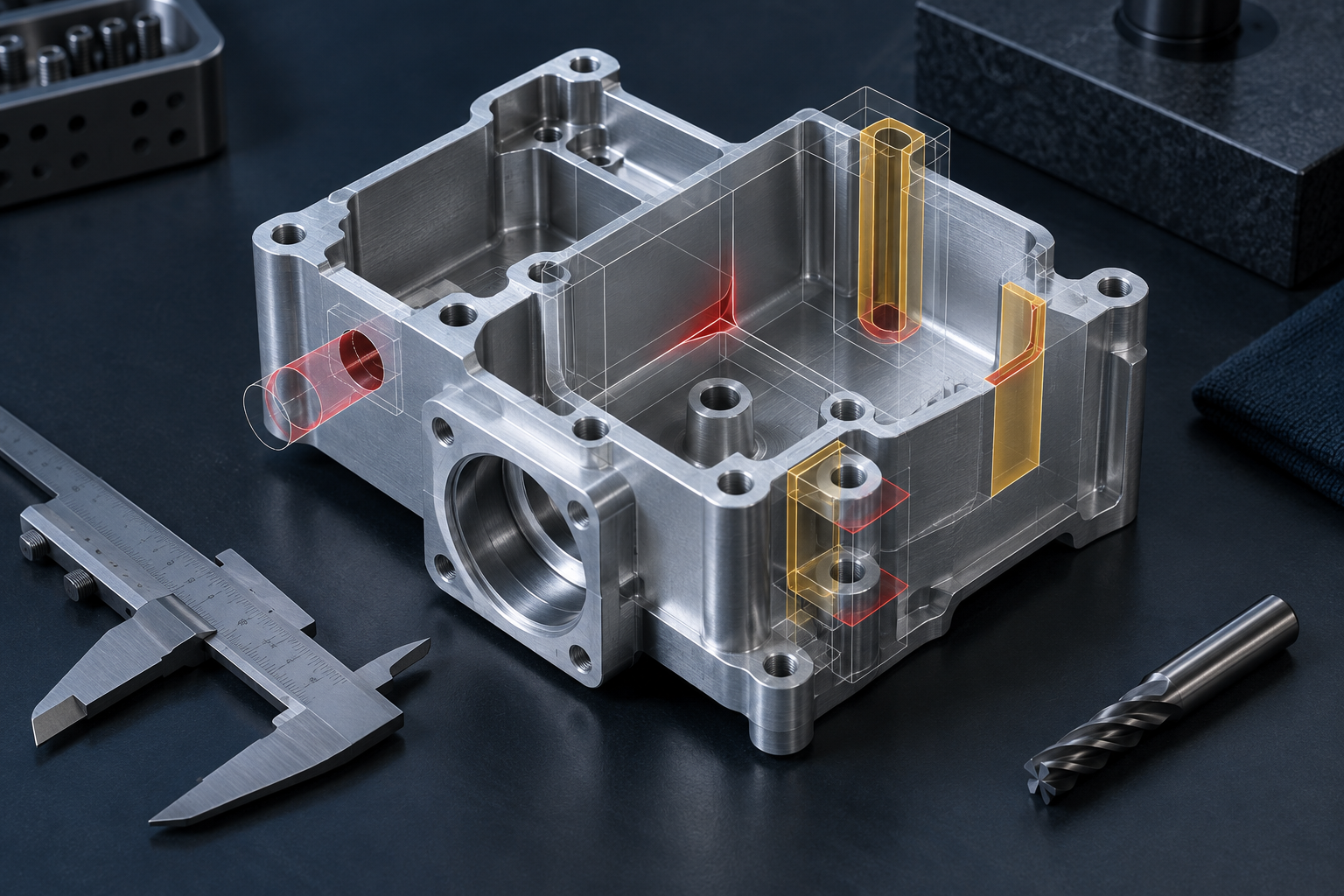
How to use this guide before design release
- Find the risky feature or missing input. Use the map and 12 mistakes below to identify where work may stop.
- State the controlling function. Record the fit, seal, load, appearance or inspection result that must be protected.
- Review one concrete correction. Confirm tool access, material, datums, finishing and verification with the supplier.
- Update the controlled definition. Revise the model, drawing and acceptance plan together before programming or production continues.
Mistake, delay point and corrective action map
| Design mistake | Where work stops | Likely clarification | Preventive deliverable |
|---|---|---|---|
| Model and drawing disagree | Quotation, CAM programming or final inspection. | Which file and dimension controls? | One released revision and a documented authority rule. |
| Feature is inaccessible | Process planning and fixture design. | Can direction, geometry or process change? | Tool-access review with section views. |
| Datum scheme is unclear | Setup, CMM programming and acceptance. | How is the part located in its assembly? | Functional datum reference frame. |
| Finish is underspecified | Purchasing, masking and final inspection. | Which type, class, color, zones and final dimensions? | Complete finish and cosmetic specification. |
| Inspection request is undefined | Quality planning and shipment release. | Which characteristics, method and sampling? | Agreed inspection and reporting plan. |
Mistake 1: releasing conflicting CAD and drawing data
A 3D model may show one hole diameter while the 2D drawing shows another. A note may call for a radius that the solid model does not contain. A supplier cannot safely decide which file represents design intent. Even when the machining program is built from the model, inspection and purchase acceptance may still rely on the drawing.
Release the model and drawing together under the same revision. State whether the model is basic, which dimensions override it and which annotations control features not fully represented. Remove obsolete files from the RFQ package instead of relying on filenames such as “final-v2-new.” When a requirement changes, update the controlled definition rather than approving a permanent deviation in an email thread.
Protolabs’ broader machinability design guide also emphasizes simplifying process-dependent geometry and coordinating with the manufacturing supplier. Its service limits remain supplier-specific.
Mistake 2: designing features the tool cannot reach
Side holes behind a wall, closed undercuts, internal channels and deep features near tall obstructions can block the cutter, holder, spindle or probe. A CAD model confirms geometry, but it does not prove a physical tool can approach without collision.
Review each feature by approach direction. Open a wall, relocate the feature, add assembly access, split the component or approve another process when function allows. Multi-axis equipment can improve access, but it does not eliminate holder clearance, cutter radius or inspection constraints. See multi-axis aluminum machining for the process questions that remain.
Mistake 3: specifying perfectly sharp internal corners
A rotating end mill normally leaves a radius in a vertical internal corner. A smaller radius can force a smaller cutter and, in a deep pocket, a less rigid reach. This can add tools, passes, tool wear and programming while increasing chatter or corner-engagement risk.
Allow the largest useful radius. If a square mating part must fit, add a local dog-bone or T-bone relief, or round the mating part. Protolabs’ machined-part design mistakes guide and Xometry’s CNC CAD design guidance describe this common cutter-geometry constraint. Their specific service limits are not universal standards.
Mistake 4: combining deep pockets with thin walls
Deep removal releases material stress and requires longer tool reach. Thin remaining walls deflect under cutting and clamping forces. When both features occur together, the cutter and workpiece can move at the same time. A first-off part may appear acceptable while a longer production run reveals drift, chatter or released-state movement.
Reduce pocket depth, open access, increase radii, preserve support, add ribs or split the design where possible. Select alloy, temper and stock form with the geometry in mind. Review these conditions during aluminum CNC milling planning and use the aluminum temper guide to understand why a stress-relieved designation cannot compensate for weak geometry.
Mistake 5: ignoring workholding and the released condition
A designer may use every external surface for functional geometry, leaving no robust clamp area. Thin covers and open frames can be pulled flat in a fixture, machined, then spring away after release. Cosmetic requirements can also prevent clamps from touching the easiest surfaces.
Provide stable locating features and practical clamp zones. Define whether a flexible part is accepted free-state or restrained, and how that condition relates to assembly. A sacrificial tab, temporary boss, soft-jaw nest or distributed support may be useful, but removal and final inspection must be included in the process.
Mistake 6: using an ambiguous datum scheme
Coordinate dimensions from arbitrary model origins do not necessarily express how a part fits. If machining uses one reference, inspection another and assembly a third, feature relationships can be correct in each local system yet fail at integration.
Select datums from functional contact and degrees of freedom. Ensure the features are stable, accessible and repeatable in fixtures and inspection. ASME describes Y14.5-2018 (R2024) as establishing symbols, rules and definitions for dimensioning and tolerancing. Use the standard and edition required by the project rather than mixing conventions.
Mistake 7: applying tight tolerances to every dimension
A blanket tight tolerance can turn clearance, cosmetic and stock dimensions into high-control features. It expands programming, finishing and inspection work and creates nonconformances that may not affect the product. Conversely, leaving a critical sealing or locating relationship under a broad title-block tolerance can cause assembly failure.
Assign individual controls to fits, seals, bearings, alignment and load paths. Use a suitable general tolerance for the remainder, with clear scope. The guide Aluminum CNC Machining Tolerances: What Is Practical? explains the difference between machine performance, feature tolerance and verified conformance.
Mistake 8: omitting alloy, temper or product form
“Aluminum” is not enough. Alloy affects strength, corrosion and machinability; temper and product form affect specified properties and material history. Plate, bar, extrusion and cast stock can require different allowances, fixtures and inspection logic.
State the recognized alloy and temper, governing material specification, product form, thickness or section where relevant, and permitted substitutions. Use the aluminum alloy selection guide before releasing the RFQ.
Mistake 9: treating threads as simple cosmetic holes
A threaded feature needs thread system, nominal size, class or fit, depth, entry condition and any insert requirement. Blind threads need enough room for drill point, tap lead and chip control. Threads near thin edges or intersecting holes may weaken the feature or complicate deburring.
Use standard thread sizes where the assembly permits. Distinguish full thread depth from drilled depth, and show whether a coil, key-locking or solid insert is required. Identify torque, repeat-service or galvanic concerns when they control the solution.
Mistake 10: adding vague deburring and edge notes
“No burrs” or “break all edges” may sound clear but can conflict with sealing edges, sharp datum intersections or tiny internal passages. Some edges are readily accessible; others require hand work, special tooling or a different sequence.
Identify handling edges, sealing interfaces, electrical contacts and cosmetic boundaries. Define measurable chamfers or radii only where function needs them, and specify cleanliness for enclosed channels. Avoid requiring the same treatment on every intersection by default.
Mistake 11: specifying finishing too late
Anodizing, coating, blasting and polishing affect masking, racking, appearance, handling and final dimensional acceptance. A late finish change can invalidate tolerances, fixtures, lead time and cost.
State the finish specification, type or class, color/appearance reference, cosmetic zones, protected threads and electrical or precision interfaces. Clarify which dimensions apply after processing. Coordinate the drawing with the surface-finishing plan and requirements for anodized aluminum parts.
Mistake 12: requesting inspection reports without a plan
“Full inspection report” can mean first article, every drawing dimension, critical features only, every part or a lot sample. If the scope is unresolved, the supplier cannot plan equipment, fixtures, time or shipment release.
Define characteristics, report format, sampling, traceability, acceptance stage and any customer-specific forms. NIST’s work on uncertainty and dimensional calibrations explains why a reported measurement is an estimate with associated uncertainty. Match the method and decision rule to the tolerance and risk through the quality and inspection plan.
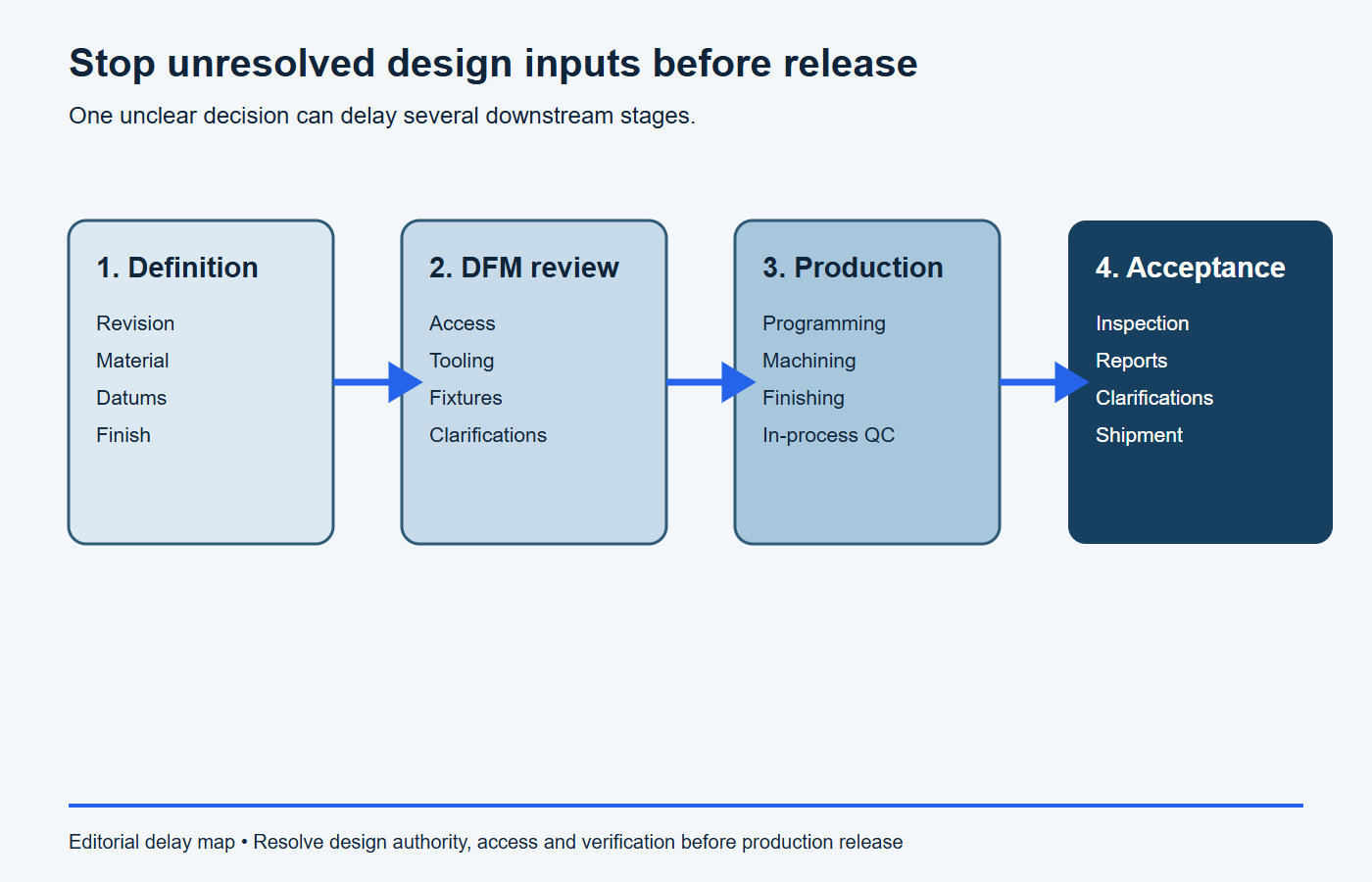
How design errors compound into schedule delay
The diagram shows why a small ambiguity can propagate through quotation, programming, tooling, production and inspection. Catching it before release avoids repeated work across several departments.
Use a pre-release design checklist
| Review area | Release question | Evidence | Owner |
|---|---|---|---|
| Product definition | Do model, drawing, notes and revision agree? | Controlled release package and change record. | Design authority. |
| Manufacturing access | Can tools, holders, fixtures and probes reach required features? | DFM markup and agreed process route. | Design and supplier. |
| Functional controls | Do datums and tolerances protect assembly without controlling irrelevant geometry? | Tolerance review and mating-part context. | Design/quality. |
| Material and finish | Are alloy, temper, stock form, finish and final condition complete? | Specifications and approved substitutions. | Design/purchasing. |
| Verification | Are inspection method, sampling, reports and traceability agreed? | Quality plan and acceptance criteria. | Quality/supplier. |
Stop conditions: do not release the design yet
- The model, drawing, notes or revision identifiers conflict.
- A tool, holder, clamp, deburring tool or inspection probe cannot reach a required feature.
- Datums do not reproduce how the part locates in its assembly.
- Blanket tolerances control nonfunctional geometry without a measurement plan.
- Alloy, temper, product form, finish or final acceptance state is incomplete.
- Threads, inaccessible burrs, sealing edges or cleanliness requirements are ambiguous.
- Supplier clarifications exist only in email and have not been added to the controlled files.
Copy-ready production DFM checklist
- Matching 3D model and 2D drawing revisions.
- Alloy, temper, product form and material specification.
- Functional datums, critical fits, seals and mating-part context.
- Tool-access-critical sections and allowed geometry changes.
- Finish, masking, cosmetic zones and final acceptance condition.
- Prototype, production and repeat quantities.
- Inspection reports, sampling and traceability requirements.
- Required approval route for supplier questions and deviations.
Use BAOSONG’s engineering-support resources to organize the package, or send the controlled drawing and application requirements for a manufacturability review. Resolve questions before programming begins so manufacturing can work from one approved definition.
Frequently asked questions
Can a machinist simply correct a poor CNC design?
A supplier can propose changes, but should not alter fit, safety, material or acceptance requirements without design approval. Record approved changes in the controlled model and drawing.
Does five-axis machining remove the need for DFM?
No. Five-axis access can reduce setups for suitable geometry, but cutter reach, holder collision, workholding, thin-wall stiffness, finishing and inspection still require review.
When should DFM happen?
Before the production drawing is frozen and again when quantity, material, finish or manufacturing route changes. Early review preserves more design options and avoids reprogramming.
What is the fastest way to answer a supplier clarification?
Identify the controlling function, approve a specific revised requirement, update the controlled files and return one traceable decision. Avoid parallel email answers that create competing interpretations.
Recommended Downloads for CNC Machining Design
Use these BAOSONG references to improve tool access, feature geometry, practical tolerances and CNC process planning before release.
- Aluminum CNC Machining Design Guide (PDF)
- CNC Milling Guide: Pockets, Walls, Corners & Tool Access (PDF)
- CNC Turning Guide: Diameters, Threads & Concentric Features (PDF)
- CNC Machining Tolerance Guide (reference sheet)
- Aluminum Part Design Checklist (editable Excel)
Need help reviewing a machined part or feature stack? Contact BAOSONG Precision.
