
Quick answer: what aluminum extrusion tolerances do designers need to specify?
Designers should specify only the aluminum extrusion tolerances that protect fit, sealing, alignment, appearance or downstream machining. Treat cross-sectional dimensions, wall thickness, straightness, twist, flatness, angularity and cut length as separate characteristics because each describes different variation and requires a suitable inspection method.
Start with the standard tolerance framework that applies to the ordered product, alloy and temper, then identify the few critical-to-function features that need project-specific control. In North American practice, ANSI H35.2 and Aluminum Standards and Data are common references; other projects may use EN or another contractually agreed system. State the standard and edition instead of writing “standard tolerance” without a definition.
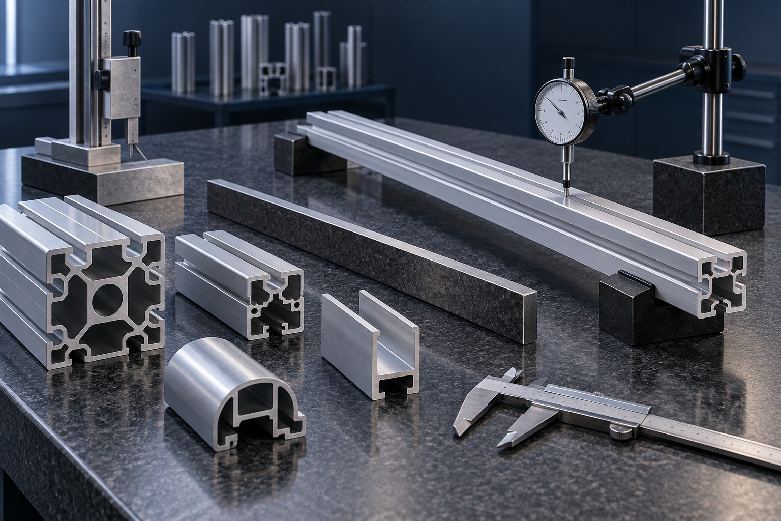
Do not apply CNC-style tolerances to an entire as-extruded profile. Where a local hole, bearing seat, sealing land or end relationship needs greater control, design enough machining stock and establish that feature later from functional datums. Agree with the supplier on the inspection setup before releasing the die.
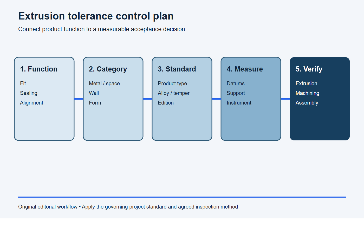
Use this tolerance workflow before drawing release
- Identify the functional interface: mark the fit, seal, alignment, load, appearance or machining stock that the requirement protects.
- Classify the characteristic: separate metal and space dimensions, wall thickness, straightness, twist, flatness, angle and cut-end requirements.
- Select the control route: apply the governing extrusion standard where suitable and reserve CNC machining for justified local precision.
- Define verification: agree on datum, support, measurement span, part condition, equipment, sampling and reporting before tooling release.
Why extrusion tolerances differ from machined-part tolerances
Hot aluminum moves through a die, then cools, is stretched or straightened as required, and is cut to length. Metal flow, die condition, alloy, temper, section size, wall distribution, cooling and handling all influence the resulting geometry. The process creates a continuous near-net section, but it does not establish every surface from a rigid datum system in the same way that a CNC setup can.
This distinction changes the drawing strategy. Use the extrusion to create continuous walls, rails, fins, channels and material near the final shape. Reserve secondary machining for localized relationships that need a more controlled datum chain. BAOSONG’s comparison of extrusion and machining from solid billet explains where this combined route is useful.
| Requirement | As-extruded control | Possible finished-part control |
|---|---|---|
| Continuous channel opening | Space dimension over the profile cross-section | Functional gauge or localized machining if a precise interface requires it |
| Long mounting surface | Flatness across the face plus straightness and twist along length | Machined pads, adjustable assembly or a separate precision rail |
| Wall or rib thickness | Metal or wall-thickness tolerance under the product standard | Machine only where local stock or interface thickness matters |
| Cross-hole position | Not created by the extrusion cross-section | CNC machine from the finished-part datum system |
Use the correct standard and product category
The Aluminum Association lists ANSI H35.2-2024 as the American National Standard for dimensional tolerances for aluminum mill products. The applicable table depends on product form and may also distinguish bar, solid profiles, semi-hollow profiles, hollow profiles or tube. A value copied from the wrong product category or edition can create a false requirement.
Place the governing material and dimensional standards, editions and units in the controlled drawing or purchase specification. Confirm the alloy and temper covered by the selected table. If a customer drawing uses another national or company standard, agree on one controlling requirement for each characteristic rather than mixing whichever value appears tightest.
The Aluminum Association’s extrusion tolerance video series explains the structure and measurement of common categories. Use it as guidance, then obtain and apply the current controlling standard rather than reproducing an old online table without its notes.
The Aluminum Extruders Council’s extrusion design guidance describes tolerance, fabrication and finishing as connected design considerations and recommends discussing complex profiles with a qualified extruder. That review is especially important when the profile combines demanding geometry, a precision requirement and a specific inspection setup.
Understand metal dimensions and space dimensions
A metal dimension measures material, such as the thickness of a solid section or a distance substantially occupied by metal. A space dimension controls an opening, channel or other distance substantially occupied by space. The distinction matters because the applicable tolerance can depend on how the dimension crosses the profile and on whether the section is solid or hollow.
Dimension the interface that performs the function. If a sliding component enters a channel, the functional opening and the internal envelope may matter more than several chained wall locations. If a screw port needs minimum material for engagement, wall and port geometry may control the design. Avoid redundant dimensions that over-constrain the nominal CAD profile or produce conflicting acceptance decisions.
Treat wall thickness and eccentricity as process-dependent
Wall thickness is affected by metal distribution, die support and the geometry surrounding the wall. A wall that completely encloses a space can involve eccentricity or wall variation around the void, so a single nominal thickness does not fully describe the possible condition. The relevant standard notes and profile classification must be considered.
Do not assign one universal wall-thickness tolerance to every rib, web and hollow. Mark the walls that protect strength, heat transfer, thread engagement, machining stock or cosmetic behavior. Let noncritical thicknesses follow the agreed standard where possible, and review unusually thin, long or unbalanced sections with the extruder before tooling.
Distinguish straightness, twist and flatness
These characteristics are often confused, especially on long profiles:
- Straightness limits longitudinal bow or curvature along the extrusion.
- Twist describes rotation of the cross-section about the profile’s length axis.
- Flatness controls curvature across the width of an individual surface.
A profile can meet one requirement and fail another. A broad face may be locally flat across its width while the whole rail bows along its length. A straight centerline does not guarantee that mounting faces maintain the same rotational orientation from one end to the other. The Aluminum Association identifies different tables and measurement procedures for these categories, including separate flatness treatment for solid and hollow profiles.
| Characteristic | Functional question | Inspection definition needed |
|---|---|---|
| Straightness | Will bow prevent insertion, alignment or mounting over the engaged length? | Evaluation length, profile orientation, support condition and reference line |
| Twist | How much relative rotation can mating faces accept from end to end? | Controlled face, length, support condition and angular or equivalent linear method |
| Flatness | Does a face need uniform contact for mounting, sealing or appearance? | Surface, transverse span, solid or hollow classification and measurement method |
Specify length, end squareness and angularity separately
Cut length does not automatically control the squareness of each cut face. A saw-cut blank may satisfy a length range yet still be unsuitable as a precise assembly datum. If the end locates another component, state whether the final face is saw-cut, faced by CNC machining or controlled by a separate squareness requirement.
Angularity within the cross-section is also distinct from cut-end squareness. A nominal 90-degree corner between profile walls, the angular position of a sloped feature and the relationship of a cut face to the length direction are different inspection tasks. Dimension the relationship that affects the product.
Define contour, corner radii and profile-of-surface requirements carefully
Curved extrusion surfaces and complex contours may not be adequately controlled by a chain of simple linear dimensions. The product standard may contain contour, angularity, corner or fillet-radius categories. When geometric tolerancing is needed for a functional surface, use the drawing standard correctly and avoid duplicating controls.
ASME Y14.5-2018 (R2024) provides rules for dimensions, datum reference frames and geometric tolerances. It does not replace the extrusion mill-product standard. A drawing can use GD&T to express finished-product function while using the agreed extrusion standard for stock dimensions and form, provided the scope and inspection condition are clear.
Choose datums from stable functional surfaces
A datum feature should represent how the profile locates in the finished product or in secondary machining. Broad accessible pads or rails are usually easier to fixture and inspect than flexible lips, thin fins or narrow cosmetic edges. If a mounting face will be machined, define the relationship of the final datum to the available extrusion stock.
Long flexible profiles can change shape under their own weight or under clamping. The inspection plan should state orientation, support points and permitted restraint. A result measured with the part forced against a surface is not automatically equivalent to its free-state condition. Use the condition that represents the governing drawing and assembly function.
Account for measurement method and uncertainty
A tolerance is incomplete in practice if supplier and customer measure it differently. Define the measurement span, datum setup, instrument, fixture, part condition and sampling plan for critical characteristics. A caliper may be suitable for an accessible cross-sectional dimension, while a functional gauge, surface plate setup, optical method or coordinate measurement may be better for another feature.
Measurement equipment should be calibrated and capable of resolving the acceptance decision. NIST’s measurement and calibration resources cover dimensional services and traceability. Project inspection still needs a suitable uncertainty relative to the specified tolerance, plus control of temperature and handling where they materially affect the result.
Allow for anodizing, coating and downstream processing
Surface treatment can affect the dimension and acceptance condition of mating features. State whether a dimension applies before or after anodizing or coating, and identify masking, electrical-contact, threaded, cosmetic and sealing areas. Do not assume that a nominal CAD clearance remains unchanged through the complete finish route.
Appearance requirements also need their own acceptance criteria. Die lines, handling marks, gloss and color variation are not fully defined by dimensional tolerances. Establish cosmetic zones, surface preparation, reference samples and viewing conditions. BAOSONG’s pages on anodized aluminum and surface finishing outline the downstream questions to review.
Decide when secondary CNC machining is justified
Machining is appropriate when a local feature needs a tight relationship to a functional datum, a precise end face, controlled bore, pocket, thread or sealing land. It should not be used automatically to correct a poorly defined tolerance scheme. First determine the assembly requirement, then choose the least complex process route that can verify it.
Provide enough stock around machined features to cover expected profile variation, and avoid locating from an unstable as-extruded surface. BAOSONG’s aluminum CNC tolerance guide and aluminum CNC milling service explain the separate controls used after extrusion.
Common tolerance mistakes on extrusion drawings
- Writing “standard tolerance” without a standard and edition: the supplier cannot know which table or product category governs.
- Using equal plus/minus limits on every CAD dimension: the drawing may over-constrain nonfunctional geometry.
- Confusing flatness with straightness: transverse surface form and longitudinal bow require different controls.
- Ignoring twist: two ends may be rotationally misaligned even when local dimensions pass.
- Chaining across many walls and spaces: accumulated variation can make the functional interface unpredictable.
- Using a saw-cut end as a precision datum without defining it: length and end squareness are separate requirements.
- Leaving measurement setup undefined: support and clamping can change the apparent result on a flexible profile.
- Ignoring the post-finish condition: mating, cosmetic and electrical surfaces may change after treatment.
Stop conditions: the tolerance requirement is not ready
- The drawing says “standard tolerance” but omits the standard, edition, units or applicable product category.
- A single control is being used interchangeably for straightness, twist and surface flatness.
- A critical feature has no functional datum, inspection span, support condition or finished-state definition.
- Machining stock has not been checked against expected extrusion variation and fixture location.
- Supplier and customer use different measurement methods or acceptance conditions for the same characteristic.
Copy-ready extrusion tolerance review request
Please review extrusion [part number/revision] to the proposed standard [document, edition and units]. For each marked critical characteristic, confirm the product category, tolerance table or project-specific limit, datum, part condition, support method, measurement span, equipment and reporting method. Identify any requirement that should be CNC machined rather than controlled as extruded. Confirm allowance for finish and machining stock, then list all drawing changes required before die release.
A designer’s extrusion tolerance checklist
- Identify the few dimensions and forms that directly control product function.
- Confirm profile classification, alloy, temper and governing tolerance standard.
- Separate metal dimensions, space dimensions and wall-thickness requirements.
- Assess straightness, twist and flatness independently over relevant lengths.
- Define cut length, end condition and angular relationships separately.
- Select accessible functional datums and avoid flexible references.
- State the inspection method, orientation, support condition and sampling for critical features.
- Define whether acceptance is before or after finishing and secondary machining.
- Use CNC machining only where the functional relationship justifies it.
- Review the controlled drawing with the extrusion supplier before tooling release.
Frequently asked questions
What is a standard aluminum extrusion tolerance?
It is a permitted variation defined by an identified product standard and table for the relevant product form, alloy, temper, size and characteristic. “Standard” alone is ambiguous; specify the document and edition in the purchase requirements.
Can an aluminum extrusion have tighter than standard tolerances?
Some characteristics may be capable of tighter control after supplier review, while difficult geometry may require a different approach. Confirm the profile, quantity, inspection method and process route instead of assuming that a precision-table value is guaranteed.
How are straightness and twist different?
Straightness limits longitudinal curvature. Twist limits rotation of the cross-section along the length. Both may affect a long assembly, so they should be evaluated separately using an agreed support and measurement method.
Should a designer specify every extrusion dimension as critical?
No. Mark the characteristics that control fit, sealing, load, motion, appearance or machining stock. Let noncritical geometry follow the agreed standard where possible to reduce conflicting requirements and unnecessary inspection.
Request an extrusion tolerance review
BAOSONG supports profiles that combine aluminum extrusion services, machining and finishing. Review BAOSONG’s quality approach and engineering support, then send the controlled drawing, model, alloy and temper, critical characteristics, finish, inspection documents and order quantity through the contact page for engineering review and quotation.
Recommended Downloads for Aluminum Extrusion Design
Use these BAOSONG references to set profile geometry, wall thickness, tolerances and downstream CNC features before releasing an extrusion design.
- Custom Aluminum Extrusion Design Guide (PDF)
- Wall Thickness and Tolerance Guide (PDF)
- CNC Machining Guide for Aluminum Extrusions (PDF)
- Aluminum Alloy Comparison Chart (editable Excel)
Need help checking an extrusion profile or manufacturability risk? Contact BAOSONG Precision.
