
Quick answer: how can custom aluminum extrusions reduce assembly parts?
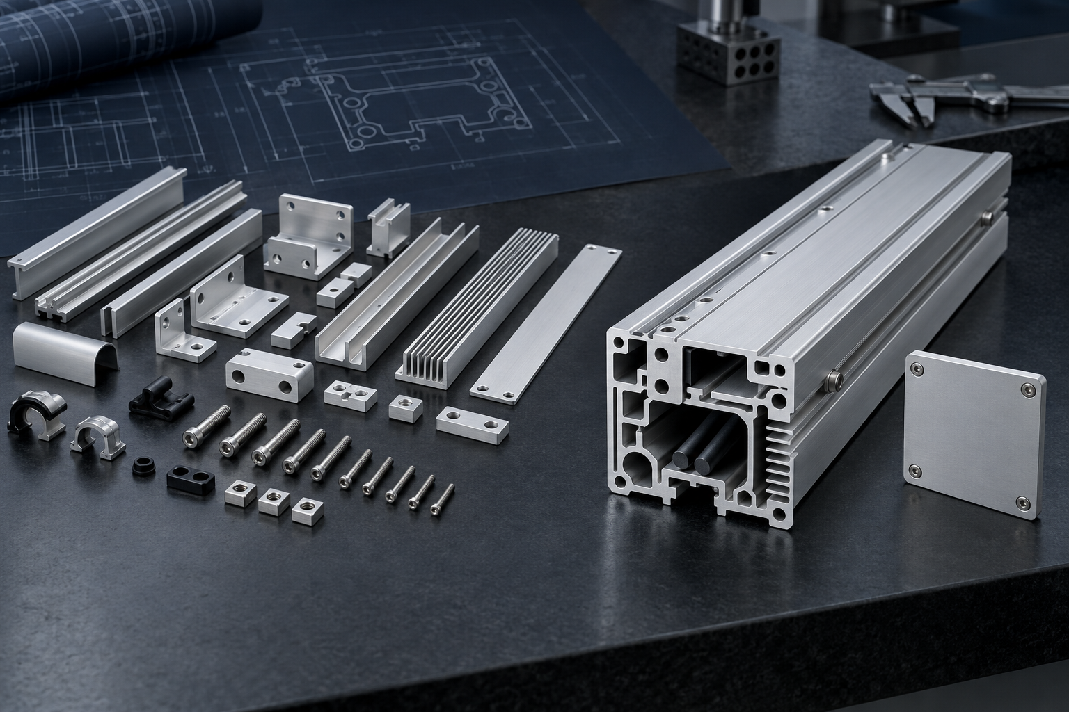
Custom aluminum extrusion part consolidation works by turning functions that repeat along a product’s length into one continuous cross-section. Separate rails, brackets, cable guides, heat-sink fins, screw ports, panel grooves, alignment features and mounting pads may become integrated geometry when they use the same material, do not need relative movement and can share one practical tolerance and finishing route.
Begin with the existing bill of materials and assembly sequence. For every part, ask whether it must move, use a different material, remain replaceable, be installed before another component, or require an incompatible process. Preserve parts that satisfy those needs. Combine the remaining continuous functions only when the new profile can be extruded, cut, machined, finished, inspected, assembled and serviced reliably.
A lower part count does not guarantee a lower finished-product cost. Integration can reduce purchasing, handling, fixtures, fasteners and assembly steps, but it can also increase profile weight, die complexity, machining time or change risk. Compare total recurring and one-time cost at the expected volume before releasing tooling.
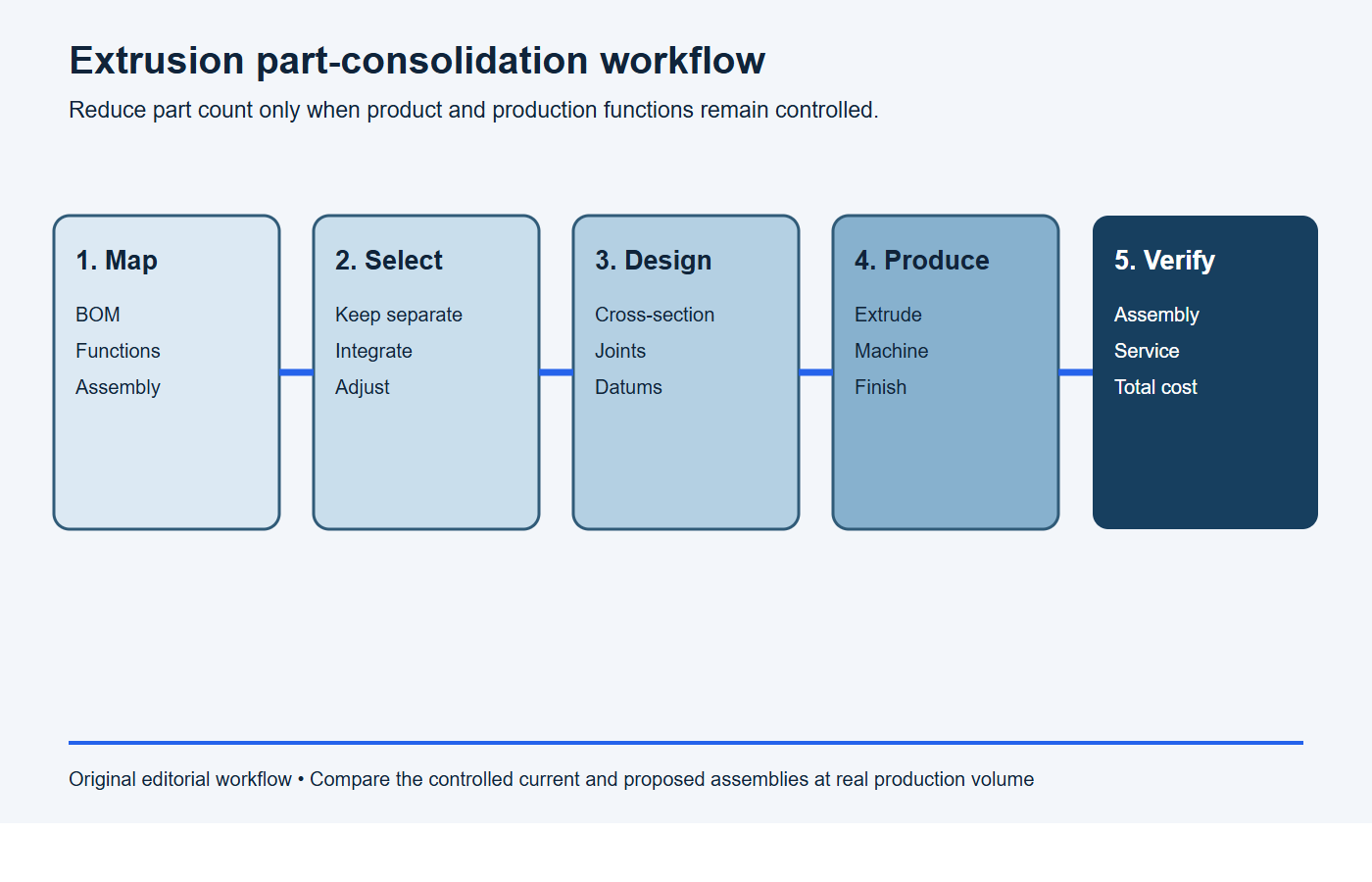
Use this part-consolidation process before redesigning the assembly
- Map the current route: list parts, suppliers, fasteners, fixtures, handling and every assembly operation.
- Separate functions from parts: identify continuous load, location, enclosure, thermal, routing and fastening needs.
- Build a candidate profile: integrate compatible continuous functions while preserving motion, service and installation access.
- Compare complete routes: include tooling, material, machining, finishing, inspection, inventory and change risk.
- Validate before release: test representative assemblies for fit, loads, heat, finish, service and repeatability.
Start with function, not the current part boundaries
Existing assemblies often reflect earlier manufacturing decisions rather than the minimum number of functional components. A bent bracket may exist because the original design used sheet metal. A separate rail may have been selected because only stock rectangular tube was available. A spacer may compensate for a datum relationship that could be built into a custom profile.
Map the functions independently of the current parts:
- carry bending, torsion, impact or clamp loads;
- locate, guide or retain another component;
- enclose, shield, ventilate or drain;
- transfer or reject heat;
- route cables, seals, air or other non-pressure services;
- provide fastening, adjustment or service access;
- create cosmetic exterior surfaces.
The Aluminum Extruders Council notes that extrusion geometry can aid assembly and reduce or eliminate forming and welding operations in its design guidance. That opportunity should be evaluated against product function and manufacturability rather than treated as a universal result.
| Current component | Potential integrated feature | Reason to keep it separate |
|---|---|---|
| Continuous mounting rail | Extruded T-slot, dovetail, groove or datum pad | Rail needs different wear material, replacement or precision class |
| Repeated spacer | Extruded rib, web or step | Spacing varies by model or needs field adjustment |
| Cable guide | Open channel or enclosed routing space | Cable must be installed later and cannot enter the continuous channel |
| Heat sink | Fins and thermal base integrated into enclosure | Thermal interface, alloy, orientation or service strategy favors a separate sink |
| Corner bracket | Continuous boss, joint rail or end-fastening port | Bracket supplies adjustability, disassembly or load distribution the profile cannot replace |
Use minimum-part-count questions before combining parts
A part is a strong consolidation candidate when it has no required motion relative to its neighbors, does not need a different material or isolation, and does not have to remain separate for assembly or service. It becomes a weak candidate when combining it blocks access, removes adjustment, makes repair uneconomical or couples conflicting requirements.
Review each part with four questions:
- Must it move independently during normal operation?
- Must it use a different material, finish, hardness, electrical behavior or thermal condition?
- Must it remain separate so the product can be assembled, adjusted, inspected or serviced?
- Would integrating it create an extrusion, machining or quality requirement that is harder than the removed operation?
Keep a separate component when any answer establishes a real product need. The goal is a simpler complete assembly, not the smallest possible BOM at any cost.
Integrate continuous locating and mounting features
Rails, grooves, datum pads, stops and captive-hardware channels can replace added brackets or welded attachments. Continuous geometry can also provide repeatable locations along multiple cut lengths, which is useful across a product family. The feature should transfer load into stable walls and webs rather than flexible lips.
Model the actual mating hardware and assembly path. A T-nut needs an insertion route. A sliding panel needs clearance across length, straightness and twist variation. A cover groove needs space for finish buildup and gasket compression. An integrated feature that cannot be loaded or serviced may add more assembly work than it removes.
Combine enclosure, thermal and structural functions carefully
An extrusion can serve as an enclosure wall, structural beam and heat sink at the same time. This can remove a separate housing, frame and thermal component, plus their brackets and fasteners. It may also reduce thermal interfaces by placing fins and mounting base in one continuous aluminum section.
These functions can conflict. A structural wall may need stiffness in a direction that adds material to the thermal path. Fins need air exposure and spacing. An enclosure needs sealing, access and cosmetic surfaces. Electronics may require electrical isolation or controlled grounding. Treat the combined profile as a system and validate structural, thermal, environmental and assembly requirements together.
Do not claim that an enclosed extrusion is leak-tight. Hollow-die metal-flow routes, open cut ends, ports, fasteners, gaskets and finishing all affect sealing. If the component carries a fluid or must exclude moisture, define the full joint and a suitable test method.
Replace brackets and weldments only when the load path remains clear
A separate bracket can distribute load, create a gusset, allow adjustment or join members at an angle. An integrated rib or boss may replace it when the profile and end connection provide the same verified function. Calculate load transfer through the profile walls, fastener bearing, local bending and joint slip rather than comparing part outlines.
Removing a weld can avoid heat-affected distortion and a separate welding operation, but the replacement joint still needs strength, stiffness, fatigue and corrosion review. End screws, inserts, T-nuts, adhesive joints or mechanical interlocks each introduce their own requirements. Prototype the joint under representative assembly and service conditions.
Use screw ports and channels to remove hardware selectively
Continuous screw ports can support end plates or repeated attachment positions, while captive-nut channels can make brackets adjustable without drilling multiple holes. Panel grooves and snap features can reduce clips or separate retainers. Cable channels can replace stand-alone trays.
Each feature needs a defined use. A screw port must be designed with the selected fastener, engagement method, assembly torque and load. A narrow channel must remain extrudable and allow hardware insertion. A snap feature must tolerate assembly strain and required service cycles. Avoid adding every possible feature to one “universal” profile if most products carry the unused material.
Preserve assembly sequence and service access
Part consolidation can create a geometric trap. A component that was previously placed before two brackets were joined may no longer enter a closed integrated channel. A fastener may become inaccessible behind a rib. A cable may need an end-loading path that conflicts with an installed connector.
Create a step-by-step digital assembly and service sequence. Check hand and tool access, component orientation, insertion distance, cable bend radius, fastener approach, torque-tool clearance, gasket placement and removal of failed components. Include realistic manufacturing variation rather than testing only nominal CAD geometry.
Decide whether adjustability belongs in the profile or the joint
Separate brackets often absorb dimensional variation through slots, shims or loose assembly before final tightening. Removing them can make the integrated profile responsible for alignment that the previous system adjusted during assembly. Preserve adjustability where the product or installation needs it.
An extruded slot can provide continuous adjustment. A machined hole can provide fixed location. A separate insert can supply wear resistance or replaceable threads. Choose deliberately and define which datum controls the final assembly.
Design the consolidated cross-section for manufacturability
Combining parts increases the number of functions in one profile, which can enlarge the circumscribing circle, add hollows, deepen channels and create uneven walls. The AEC’s key design considerations emphasize balanced walls, practical symmetry, reduced deep tongues and reasonable section complexity. A profile that integrates many parts still has to flow through a die and remain stable during cooling and straightening.
Use gradual wall transitions and practical radii. Split difficult geometry into an extrusion plus cover when that preserves most of the consolidation benefit. The AEC’s broader design resources also connect extrusion design with machining, welding, bending, bonding and finishing—useful when one integrated profile still needs downstream operations.
Manage tolerance stacks after part consolidation
Removing joints can remove some accumulated variation, but it also ties multiple interfaces to one cross-section. A die correction or profile shift may affect several functions at once. Identify which dimensions control mating, sealing, motion, appearance and machining stock, then establish a datum and inspection plan.
The Aluminum Association’s extrusion tolerance guidance separates metal and space dimensions, flatness, straightness and twist. These controls matter differently in an integrated profile. A channel opening can pass while a long rail still twists; a mounting face can be locally flat while the part bows over its installed length.
Use ASME Y14.5-2018 (R2024) or the project’s specified drawing standard to communicate final datum relationships and geometric tolerances. Keep the extrusion-product tolerance framework and finished-part GD&T roles clear.
| Integrated function | Critical variation | Verification approach |
|---|---|---|
| Panel capture | Channel opening, internal space, finish and profile form | Functional gauge or representative panel across engagement length |
| Mounting rail | Flatness, straightness, twist and relation to final holes | Defined support condition plus machined-datum inspection |
| End plate joint | Cut face, boss geometry, hole preparation and gasket compression | Dimensional inspection plus torque or sealing test as required |
| Thermal enclosure | Base contact, wall and fin geometry, interface assembly | Dimensional checks plus representative system thermal test |
Use CNC machining where local precision creates value
Part consolidation does not require every feature to be as-extruded. Drilling, tapping, end facing, connector pockets, sealing lands and localized mounting pads can convert a continuous profile into an assembly-ready component. The profile should include sufficient stock and accessible datums for these operations.
Do not machine long surfaces only to compensate for an undefined extrusion requirement. Separate the as-extruded tolerance from the finished local relationship. BAOSONG’s aluminum CNC milling service and CNC tolerance guide explain how local features can be controlled after extrusion.
Plan finishing and cosmetic integration
A consolidated profile may place structural, thermal and cosmetic faces in one finishing lot. Define appearance zones, die-line expectations, masking, electrical contacts, threads, sliding surfaces and gasket lands. State whether critical dimensions apply before or after anodizing or coating.
Dense fins, deep channels and enclosed voids can complicate drainage, cleaning, racking or inspection. Discuss the full geometry with the finishing supplier. BAOSONG’s anodized aluminum and surface-finishing pages provide a starting point.
Compare the complete cost before and after consolidation
Build a cost model for the current and proposed designs. Include purchased parts, fasteners, supplier management, incoming inspection, inventory, fixtures, assembly labor, alignment, welding or bonding, scrap, rework, service and packaging. For the extrusion route, include die and development, profile weight, cut-off, machining, finish, inspection and program-change risk.
Separate one-time investment from recurring cost. A custom die may be justified by sustained demand but difficult to recover for a short prototype. A consolidated profile may reduce assembly time yet increase material in every unit. Use actual quantities and process estimates; do not apply a generic savings percentage.
Control product-family and supply-chain risk
A single integrated profile can replace multiple suppliers and drawings, but it also becomes a high-consequence item. A die change, extrusion delay or design revision can affect several functions at once. Plan qualification, tooling ownership, revision control, approved samples, safety stock and replacement-die strategy according to the program’s risk.
For product families, identify a stable common cross-section and create variants by cut length, machining or attached modules. Avoid integrating a short-lived option into every unit unless the recurring benefit exceeds the added material and change exposure.
Stop conditions: do not consolidate these parts yet
- A component needs relative motion, a different material, field replacement or an assembly step that the integrated profile would block.
- The new extrusion hides fasteners, seals, burrs, chips or inspection features required during production or service.
- Removing a bracket or joint changes the load path, thermal expansion or adjustment without analysis and representative testing.
- The cost case counts fewer parts but omits increased profile weight, die complexity, machining, finish protection or change exposure.
- The consolidated profile combines several critical functions without a tooling, qualification and supply-continuity plan.
Copy-ready part-consolidation review request
Please review assembly [number/revision] for part consolidation with a custom aluminum extrusion. The current BOM, assembly sequence, suppliers and annual quantity are attached. For each proposed integrated feature, identify the part and operation removed, the function retained, the extrusion or machining risk and the validation method. Compare current and proposed tooling, material, machining, finishing, inspection, fasteners, labor, inventory and change-control cost. Preserve service access, adjustment, replaceability and required material separation.
Part-consolidation review checklist
- Map the current BOM, suppliers, fasteners, fixtures and assembly sequence.
- Separate product functions from existing part boundaries.
- Keep parts that require motion, different materials, service or assembly separation.
- Convert suitable continuous functions into candidate extrusion features.
- Check load paths, thermal behavior, sealing, grounding and cosmetic requirements.
- Simulate assembly, adjustment, tool access and service removal.
- Review the cross-section, alloy, temper, die and tolerances with the extruder.
- Plan cutting, CNC machining, deburring, finishing and inspection.
- Compare current and proposed total cost at realistic quantities.
- Validate representative parts and assemblies before production release.
Frequently asked questions
Which parts are easiest to combine into an extrusion?
Continuous rails, ribs, channels, screw ports, enclosure walls, fins and mounting pads are common candidates. They should share compatible material, finish and tolerance requirements and should not block assembly or service.
Does reducing fasteners always improve reliability?
No. Fewer joints remove some failure opportunities, but retained joints may carry more load or lose adjustment and serviceability. Validate the new load path, assembly method and maintenance plan.
Can one extrusion replace a welded frame?
It can replace some longitudinal members, brackets or welds when the geometry and joining strategy meet structural requirements. The complete frame, corner joints, spans, fatigue and installation conditions still require analysis and testing.
When is part consolidation a poor choice?
It is less attractive when volumes cannot support tooling, options change often, parts need different materials or replacement, assembly access is lost, or the integrated profile becomes much harder to extrude and inspect.
Request a part-consolidation engineering review
BAOSONG supports projects combining custom aluminum extrusion, machining and finishing. Review BAOSONG’s engineering support and quality approach, then send the current assembly drawings, BOM, annual quantity, load and interface requirements, finish and inspection needs through the contact page for engineering review and quotation.
Recommended Downloads for Aluminum Extrusion Design
Use these BAOSONG references to set profile geometry, wall thickness, tolerances and downstream CNC features before releasing an extrusion design.
- Custom Aluminum Extrusion Design Guide (PDF)
- Wall Thickness and Tolerance Guide (PDF)
- CNC Machining Guide for Aluminum Extrusions (PDF)
- Aluminum Alloy Comparison Chart (editable Excel)
Need help checking an extrusion profile or manufacturability risk? Contact BAOSONG Precision.
