
Quick answer: should you choose an open or closed aluminum extrusion profile?
Choose an open profile when access, drainage, easy finishing, simple attachment or lower tooling complexity matters most. Choose a closed profile when the design needs an enclosed passage, protected internal space or efficient torsional and bending stiffness from a box-like section. Compare actual section properties, joints and load direction rather than assuming one geometry is always stronger.
“Open” and “closed” are useful design descriptions, but the quoting classification should be confirmed as solid, semi-hollow, hollow or tube under the applicable extrusion standard. A channel that appears open may be classified as semi-hollow depending on the partially enclosed void and opening geometry. Classification affects die design, tolerance tables and quotation.
The best geometry must also survive extrusion, cooling, straightening, cutting, finishing, CNC machining and assembly. Review wall balance, deep channels, die tongues, internal access, weld-seam considerations, finish buildup, inspection method and production quantity before releasing the die.
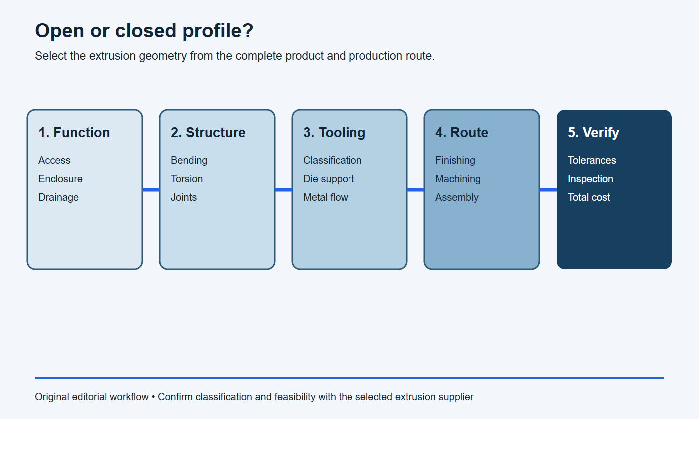
Use this five-step geometry selection process
- Define the load case: record bending directions, torsion, span, joints, allowable deflection and local attachment loads.
- Define the environment: mark access, drainage, ventilation, cleaning, shielding and any real sealing requirement.
- Compare candidate sections: calculate mass and section properties, then review wall balance, tongues, voids and die classification.
- Map downstream work: test machining, deburring, finishing, inspection and assembly access for each candidate.
- Select on total route: compare tooling, recurring processing, joints and validation at the expected production quantity.
Define open, closed, solid, semi-hollow and hollow correctly
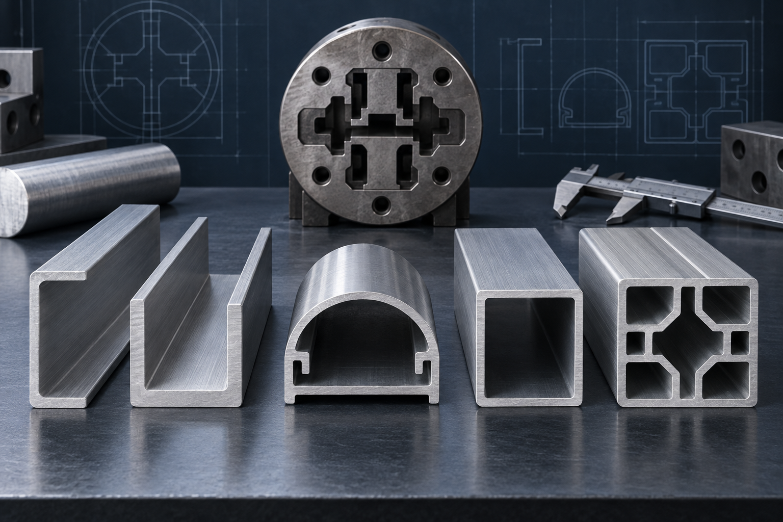
An open profile exposes its internal channel or functional surfaces through a clear opening. Common examples include angles, U-channels, C-channels and open rails. A closed profile completely surrounds at least one void, as in rectangular tube or a multi-void enclosure section.
Industry product categories require more precision. The Aluminum Extruders Council’s extrusion design guidance describes three general categories:
- Hollow shape: the cross-section completely encloses a void.
- Solid shape: the shape is neither hollow nor semi-hollow.
- Semi-hollow shape: the shape partially encloses a void, although some visually similar sections may still qualify as solid.
Do not assign semi-hollow classification from appearance alone. The gap, enclosed area, alloy and applicable definition can affect the result. Ask the extruder to identify the product class used for the die concept, quotation and dimensional tolerance tables.
| Decision area | Open profile | Closed profile |
|---|---|---|
| Access | Direct access for fasteners, cleaning, machining, coating and inspection | Internal surfaces may be difficult to reach after extrusion |
| Structure | Efficient when material is placed for the governing bending direction and joints provide stability | Often effective for torsion and multi-directional stiffness, subject to actual section properties |
| Environment | Can drain and ventilate readily but leaves components exposed | Can shield or route components but is not automatically sealed |
| Tooling | May use a simpler die route, unless a narrow opening creates a difficult tongue | Requires a hollow-die metal-flow and joining route |
| Secondary work | Easier internal access for machining and assembly | May consolidate parts but require access holes, end work or special cleaning |
Compare stiffness using the actual load case
Geometry governs how efficiently material resists bending and torsion. A closed box-like section can provide an effective continuous path around the perimeter, which is often useful under torsion or loads that change direction. An open channel can place material far from the neutral axis and perform efficiently in a primary bending direction, but its response may be more sensitive to orientation, warping and joint restraint.
Do not compare profiles only by outer width and height. Calculate or obtain cross-sectional area, second moments of area, torsional properties, mass per length and the location of the neutral and shear centers as appropriate. Then include span, boundary conditions, connections, local buckling, fastener behavior and allowable deflection. Strength and stiffness are different checks.
A closed profile is not automatically the lightest or least expensive solution. An open profile with well-placed ribs or a system with a separate cover may meet the load case using less difficult tooling. Validate the full assembly, not a free profile in isolation.
Choose an open profile for access, drainage and adaptable assembly
Open geometry is useful when operators, tools, fasteners or mating components must reach the inside. T-slots, nut channels, snap grooves and rail features can remain accessible along the length. Internal surfaces can be inspected visually, cleaned more easily and reached by cutters or finishing processes.
Open sections can also allow liquid or condensation to drain rather than become trapped. This is valuable in outdoor equipment, washdown-adjacent assemblies or structures that must dry, although corrosion performance still depends on alloy, finish, joints, crevices and the complete environment.
The trade-off is exposure and potentially lower torsional restraint. An open channel may need a cover, brace, gusset or panel to complete the load path or protect internal components. The joint between those parts becomes part of the structural and environmental design.
Choose a closed profile for enclosure, routing and torsional efficiency
Closed geometry can enclose cables, guide air, protect internal mechanisms and create a clean exterior. Multiple voids can place webs where they support loads or divide functional passages. A box section may provide efficient stiffness around more than one axis and under torsion.
However, a closed void is not automatically watertight, airtight or clean enough for a fluid circuit. Hollow extrusion tooling commonly directs metal around supports before streams rejoin. The resulting longitudinal seam region, cut ends, ports, joining method and finishing route must be evaluated for the specific sealing, pressure, cleanliness, fatigue or corrosion requirement. If a leak-tight passage is needed, define a test method and acceptance level rather than relying on geometry alone.
Understand how geometry changes the die
A conventional open solid profile may be produced with a solid or flat die. A hollow profile requires tooling that supports an internal mandrel while allowing aluminum to flow around support features and rejoin. This makes die design, metal balance and process control different. More voids and difficult internal geometry can add tooling and development complexity.
An open profile is not necessarily simple. A deep narrow channel leaves a slender tongue-like region in the die. If the opening becomes small relative to the enclosed area, the profile may be semi-hollow and the die support becomes more demanding. The AEC’s key design considerations advise reducing deep narrow tongues, balancing walls and using symmetry where practical.
Small geometry changes can alter the tool concept. Widening an opening, shortening a channel, rounding a transition or splitting a profile into an extrusion plus cover may improve die support. The chosen supplier should review these alternatives against the actual alloy, profile size, order volume and tolerance requirements.
Consider wall balance, cooling and dimensional stability
Both open and closed profiles benefit from balanced wall distribution and gradual thickness transitions. An open section may have free legs or wide panels that respond differently during cooling and straightening. A closed multi-void section may contain thick junctions where several webs meet thin outer walls. Either can twist, bow or show local flatness variation if mass and flow are difficult to balance.
Use ribs and webs only where they support structural, thermal, fastening or process functions. Avoid isolated heavy regions. Select wall thickness from function and confirm the full section with the extruder instead of applying a universal minimum or making every wall identical.
Apply the correct tolerance category
Open and closed sections may use different product classifications and tolerance provisions. The Aluminum Association’s extrusion tolerance guidance distinguishes metal and space dimensions for solid versus hollow profiles and notes that flatness treatment also differs by category. Straightness and twist remain separate characteristics along the length.
The Association identifies ANSI H35.2-2024 as the dimensional-tolerance standard for aluminum mill products. Use the current standard, correct table, notes, alloy and temper. Do not copy a hollow-profile tolerance onto an open channel or assume a tight external dimension also controls the internal fit.
| Interface | Open-profile question | Closed-profile question |
|---|---|---|
| Mating component | Which opening, leg or rail controls entry and retention? | Which internal space and wall locations control clearance? |
| Mounting surface | Will free legs spread, close or twist over the installed length? | Does the broad wall need local flatness or machined pads? |
| Cut end | Does the open section distort during clamping or sawing? | Must end squareness, burrs and internal chips be controlled? |
| Assembly datum | Is the selected leg stable and accessible? | Can the external datum locate internal or machined features reliably? |
Plan sealing, drainage and contamination control
An open profile offers a visible drainage route, but pockets, horizontal ledges and capillary joints can still retain liquid. Add drain paths and orient the profile in the installed assembly. If a cover is added, define gasket compression, fastener spacing, surface condition and service access.
A closed profile hides internal surfaces and can trap process fluids, chips or moisture if the ends are open during manufacturing. Define cleaning, drying, end caps, vents and packaging. A closed section intended only for structure should not be described as sealed without a verified sealing system and test.
Review finishing and cosmetic surfaces
Open sections provide better access to internal faces for brushing, polishing, coating and visual inspection, but exposed internal surfaces may also become cosmetic. Closed voids may receive less uniform access during some finishing and cleaning steps. The selected finisher must review racking, contact areas, drainage and solution entrapment.
For anodizing, define dimensions before or after treatment, mating clearances, electrical-contact or masking areas and approved appearance zones. BAOSONG’s anodized aluminum and surface-finishing pages outline these downstream considerations.
Compare CNC machining and assembly access
Open geometry lets tools reach internal channels and gives fixtures more options. Cross-holes, pockets and end features may be easier to deburr and inspect. Closed profiles can be stable workpieces and reduce separate components, but internal chips, inaccessible burrs and tool reach may require special planning.
Design locating pads on stable external surfaces and leave enough stock for final machining across expected extrusion variation. Use ASME Y14.5-2018 (R2024) or the project’s specified drawing standard to communicate final datums and geometric relationships. BAOSONG’s aluminum CNC milling and CNC tolerance guide cover the secondary-machining side of the route.
Compare total cost rather than die price alone
An open profile may have simpler tooling and less internal process complexity, yet require a cover, brackets, more fasteners or assembly labor. A closed profile may consolidate parts and improve structural efficiency, yet require a hollow die, internal cleaning, access machining or controlled end treatment. Material weight, die development, extrusion rate, yield, finishing, machining, inspection, assembly and packaging all belong in the comparison.
Production volume changes the decision. A tooling investment that removes recurring assembly may be attractive at sustained volume, while an open stock-like profile plus fabricated cover may suit early prototypes. No credible savings percentage can be given without the controlled section, quantities and complete process route.
Stop conditions: do not select the profile geometry yet
- The choice is based on a belief that closed is always stronger or open is always cheaper, without a defined load case.
- The selected extruder has not confirmed whether the section is solid, semi-hollow, hollow or tube.
- A closed passage is being treated as sealed without an end, joint, port and leak-test plan.
- Internal machining, chip removal, finishing, cleaning or inspection access has not been demonstrated.
- The comparison covers die price but omits material mass, secondary operations, assembly hardware and recurring quality controls.
Copy-ready open-versus-closed design review request
Please compare the open and closed profile concepts for [part number/revision and application]. Use the same load cases, material, length, finish and production quantity. Report mass, relevant section properties, product classification, die assumptions, tolerance approach, access for machining/finishing/inspection, drainage or sealing provisions, joining method and total finished-assembly route. Identify the recommended geometry, its unresolved risks and the prototype or sample tests required before tooling release.
Open-versus-closed selection checklist
- Define loads, directions, spans, joints and allowable deflection.
- Identify required enclosure, access, ventilation, drainage and cleaning.
- Calculate section properties and mass for realistic candidate profiles.
- Classify each section as solid, semi-hollow, hollow or tube with the extruder.
- Review wall balance, tongues, voids, die support and cooling behavior.
- Apply the correct dimensional and form tolerance categories.
- Check finish access, appearance zones, masking and liquid drainage.
- Plan cut-off, CNC access, deburring, internal chip removal and inspection.
- Model mating parts, joints, gaskets, end caps and tolerance stacks.
- Compare tooling and recurring finished-assembly cost at the expected volume.
Frequently asked questions
Is a closed aluminum extrusion always stronger than an open profile?
No. Structural performance depends on section properties, load direction, material, span, restraint, local stability and joints. Closed sections are often efficient under torsion, while an open section can be efficient for a defined bending direction.
Is every profile with a narrow opening semi-hollow?
No. Formal classification depends on the applicable geometric definition, including the partially enclosed area and opening. Ask the extruder to confirm the category used for tooling and tolerance selection.
Does a closed profile create a sealed passage?
No. Enclosed geometry does not by itself guarantee pressure integrity, cleanliness or corrosion performance. Define joining, ports, ends, finish and a suitable leak or functional test when sealing matters.
Which geometry is easier to machine?
Open profiles generally provide better internal tool and deburring access. Closed profiles may fixture well externally but require careful planning for internal chips, inaccessible burrs and features referenced to internal spaces.
Request an extrusion geometry review
BAOSONG supports projects combining custom aluminum extrusion, machining and finishing. Review BAOSONG’s engineering support and quality approach, then send the controlled drawing, model, load case, alloy and temper, critical interfaces, finish, quantities and inspection requirements through the contact page for engineering review and quotation.
Recommended Downloads for Aluminum Extrusion Design
Use these BAOSONG references to set profile geometry, wall thickness, tolerances and downstream CNC features before releasing an extrusion design.
- Custom Aluminum Extrusion Design Guide (PDF)
- Wall Thickness and Tolerance Guide (PDF)
- CNC Machining Guide for Aluminum Extrusions (PDF)
- Aluminum Alloy Comparison Chart (editable Excel)
Need help checking an extrusion profile or manufacturability risk? Contact BAOSONG Precision.
