
Quick answer: how should engineers design screw bosses, channels, fins and mounting features into aluminum extrusions?
Integrate a feature into the extrusion only when it performs a useful function continuously along the part: carrying a fastener load, guiding a component, routing a cable, transferring heat or providing a stable mounting reference. Design the feature as part of the whole cross-section so its wall thickness, root support and position do not create unbalanced metal flow or an unnecessarily fragile die feature.
For aluminum extrusion screw bosses, define the fastener, engagement method, assembly torque, service load and required number of assembly cycles before setting the port geometry. For channels and fins, review opening width, depth, root transitions, wall balance and tool support. For mounting features, separate as-extruded locating surfaces from holes, threads and faces that will be created later by CNC machining.
Do not use universal boss diameters, pilot holes, fin ratios or minimum walls without checking their conditions. Alloy, temper, profile size, die concept, tolerance, finish and production quantity all affect feasibility. Validate threaded or self-tapping joints, thermal performance and structural loads with representative components and an agreed inspection plan.
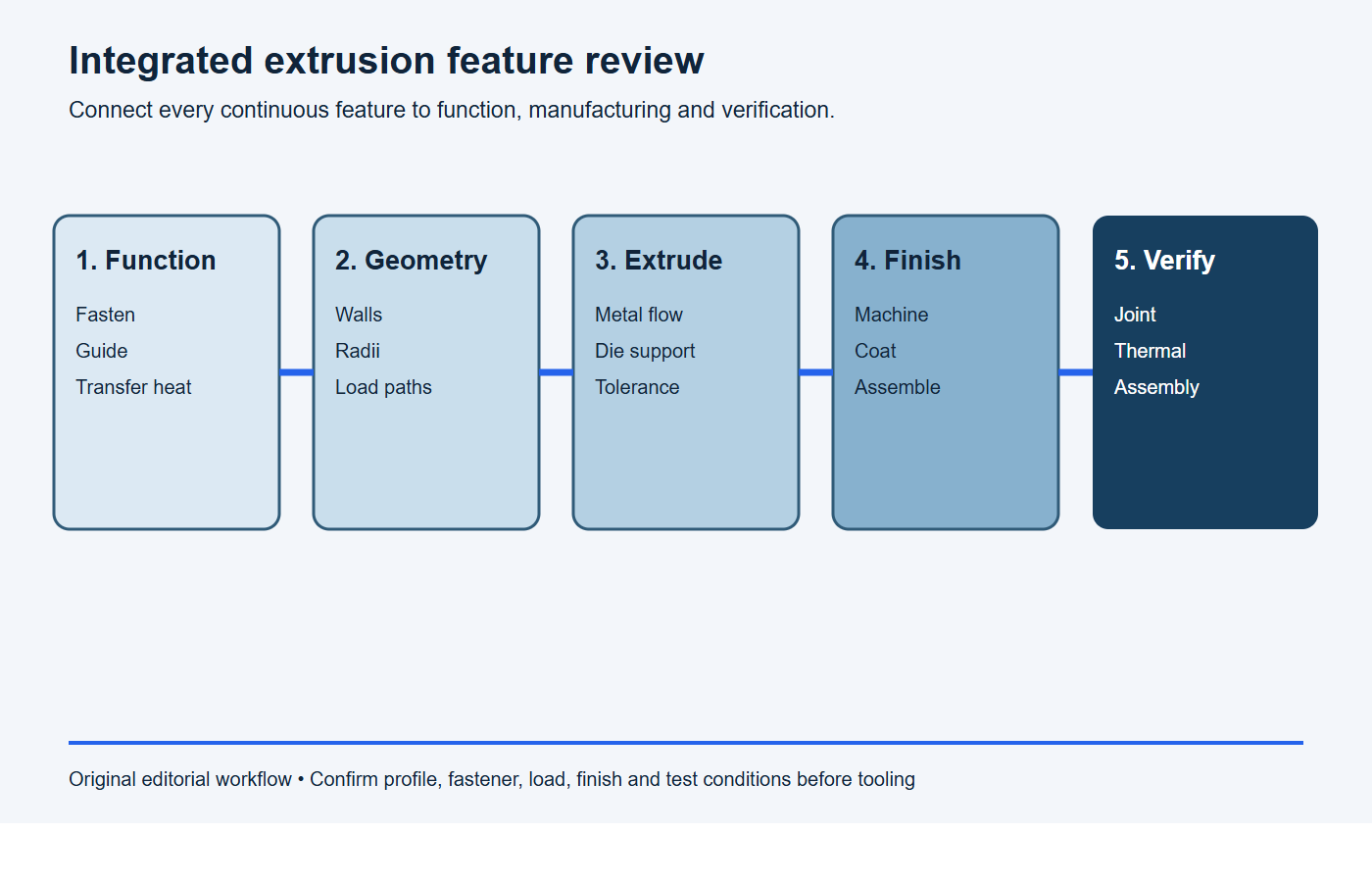
Use this feature-integration review before tooling
- Name the continuous function: state the fastener load, guided component, thermal duty or mounting relationship.
- Check the cross-section: review roots, wall balance, openings, depth, die support and finish access with the extruder.
- Separate local precision: assign holes, threads, end faces and critical relationships to controlled secondary machining where needed.
- Validate the system: test the real fastener, mating component, load, airflow and inspection method on representative parts.
Decide which features should be continuous
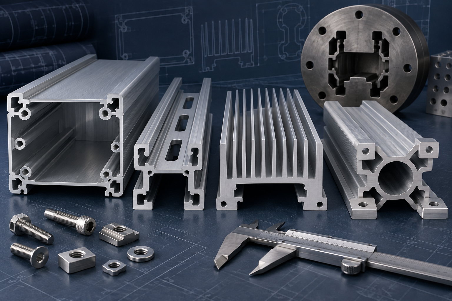
Extrusion is most valuable when a feature repeats along the length. A continuous screw port can accept end-fastening at any cut position. A rail or channel can locate panels and hardware over the full product. Fins can create heat-transfer area along an enclosure. Mounting pads can provide recurring fixture or assembly references.
A cross-hole, connector pocket, local thread, spot face or end seal does not repeat along the extrusion direction. Forcing such a local feature into the cross-section can add material or tooling complexity without removing the secondary operation. Map each feature by length and function before developing the die geometry.
| Feature | Good reason to extrude it | Consider secondary work when |
|---|---|---|
| Screw boss or port | End-fastening or attachment position repeats along the length | Thread position, axis or depth must relate precisely to a local finished datum |
| Channel or groove | Guidance, cable routing, panel capture or hardware retention is continuous | The slot is local, extremely deep or needs a precise closed end |
| Cooling fin | Heat-transfer area is required along the full thermal zone | Fin pattern is local or another heat-sink process better fits the volume and geometry |
| Mounting feature | A rail, pad or locating face supports repeated assembly positions | Holes, bores, sealing faces or bearing seats need finished-part precision |
Design screw bosses from the fastening system
An extruded screw boss is a continuous mass of material shaped to receive an end screw, a tapping operation or another fastening method after cut-off. The boss is not a complete joint by itself. Joint performance depends on the selected screw, pilot or tapped geometry, engagement length, edge distance, material condition, installation torque, service load and assembly history.
Start with the fastener supplier’s technical data and the product load case. Decide whether the screw forms its own thread, enters a machined thread, uses an insert or passes through to a nut. Determine whether assembly occurs once, during periodic service, or repeatedly over product life. A geometry suitable for one assembly may not provide the durability needed for repeated removal.
Do not infer allowable torque or pull-out strength from the nominal boss diameter. Test the actual alloy, temper, extrusion condition, screw and engagement. Acceptance can include installation torque, stripping torque, pull-out, shear, vibration or cyclic tests as the application requires.
Connect bosses to stable walls and load paths
Place the boss so the fastener load flows into the surrounding structure. An isolated heavy boss connected by a thin neck can create unbalanced metal flow and a weak load path. Blend the boss into walls or ribs with gradual transitions while avoiding unnecessary mass that can affect cooling and surface appearance.
For enclosure corners, a boss can join end plates or covers, but the fastener axis, driver access, head clearance and mating-face compression must be modeled together. Leave room for anodizing, coatings, washers, gaskets and any counterbore or spot face. If the cut end is the seating surface, specify its end condition and whether CNC facing is required.
The Aluminum Extruders Council’s introduction to extrusion dies notes that screw-lug and wall locations can affect metal flow and surface properties. Review boss position before cosmetic faces and mating components are frozen.
Design channels around the component they guide or retain
A channel can guide a panel, capture a T-nut, route wiring, hold a gasket or locate a sliding component. Dimension the functional opening and internal envelope from the mating part, including its tolerances, finish and installation angle. Avoid defining the same space through multiple chained dimensions that can conflict.
Open channels provide access for assembly and cleaning. Narrow openings and deep internal spaces increase the challenge of supporting a tongue-like feature in the die. The AEC’s key design considerations advise reducing deep, narrow tongues and keeping walls balanced. If a channel is difficult, widen the opening, shorten the depth, round the root, change the mating hardware or create part of the feature by machining.
A channel intended to retain hardware must account for insertion and removal. Define how nuts, sliders, seals or cables enter the profile and whether they can pass through bends, end caps or machined interruptions. A perfectly shaped continuous channel is not useful if the assembled component cannot be installed or serviced.
Use radii and gradual transitions at channel roots
Sharp channel roots and knife-edge lips are difficult flow transitions and can be vulnerable during handling. Use practical internal radii, lip thickness and tapers where the functional fit allows them. The exact values depend on the profile, die and mating hardware; confirm them with the extruder instead of copying a generic rule.
When the product needs a sharp-looking external edge, distinguish visual intent from the true mating envelope. A small radius, corner relief or cosmetic groove may preserve appearance without forcing an impractical metal edge.
Design fins as part of a thermal system
Fins add surface area, but useful heat rejection depends on heat flow from the source through the base and fins into moving or natural-convection air. Fin height, thickness, spacing, orientation, base thickness, airflow bypass, interface material and surface condition all interact. More fins or thinner fins do not automatically improve the complete system.
From an extrusion perspective, tall thin fins and narrow gaps create slender die features and high flow resistance. A fin field also changes the mass balance of the cross-section. Review fin aspect, root radius, base thickness and the relationship between the finned side and the rest of the profile. If necessary, reduce fin height, increase spacing, taper the fins, rebalance the opposite wall or select another manufacturing route.
Use thermal analysis as a screening tool and validate with representative hardware under defined power, interface, airflow, orientation and ambient conditions. An AI illustration or nominal alloy conductivity is not proof of assembly-level thermal performance.
Control fin straightness, spacing and handling risk
Thin fins can be damaged during cutting, deburring, racking, packaging or assembly. Define the functional zone and whether a bent fin affects airflow, fit or appearance. Protective packaging and handling fixtures may be as important as the extrusion tolerance.
Do not apply a tight flatness or position tolerance to every fin without a measurement plan. Determine whether the critical characteristic is minimum gap, total envelope, base flatness, fin height, or interference with a fan or cover. Use a functional gauge when it represents the product better than checking every individual dimension.
Build mounting features around datums and load transfer
Mounting rails, pads, dovetails, T-slots and grooves can reduce brackets and speed assembly. Their geometry should connect the applied load into webs and walls rather than into a flexible lip. Model bolt preload, joint slip, bearing, local wall deformation and the stiffness of the mating component where they affect function.
Select datum surfaces that are broad, stable and accessible to fixtures and gauges. An outer rail or pad can locate the profile for CNC machining; a thin fin or burr-prone saw-cut edge usually creates a less stable reference. If a mounting face needs finished flatness or a hole pattern needs accurate position, leave machining stock and create those features from the final datum system.
ASME Y14.5-2018 (R2024) provides rules for communicating datums and geometric tolerances. Apply it to the finished product definition while using the relevant extrusion-product standard for as-extruded dimensions and form.
Understand extrusion tolerances for integrated features
Boss centers, channel openings, fin spaces and mounting pads are affected by how dimensions cross metal and space in the profile. The Aluminum Association’s extrusion tolerance guidance distinguishes metal and space dimensions for solid and hollow profiles, as well as flatness, straightness and twist.
The Association identifies ANSI H35.2-2024 as the dimensional-tolerance standard for aluminum mill products. Apply the correct product category, table notes, alloy and temper instead of transferring one tolerance to every boss, channel or fin geometry.
A channel can meet its opening dimension while a long profile still bows or twists. A mounting pad can be locally flat across its width while changing orientation along the length. A screw port can have an acceptable cross-section but still require end preparation or tapping. Identify each functional relationship separately.
| Feature function | As-extruded control | Finished-part verification |
|---|---|---|
| End-fastening boss | Port geometry, wall condition and relation to the profile | Cut face, pilot or tapped feature, torque and joint tests |
| Sliding channel | Opening, internal space, straightness and twist | Functional gauge or mating-component travel over the required length |
| Heat-sink fins | Envelope, gaps, fin and base geometry | Handling inspection plus assembly-level thermal test |
| Mounting rail | Cross-section, flatness, straightness and twist | Machined datums, hole position and assembly alignment as applicable |
Plan CNC machining, tapping and deburring together
Extrusion creates continuous boss and channel geometry; it does not create transverse holes, local pockets or automatically finished threads. Define whether screw ports will be used as-extruded, drilled, reamed, tapped or fitted with inserts. Allow tool approach, chip evacuation and inspection access.
Channels can trap chips and make burrs hard to reach, while fins limit fixture contact and tool clearance. Establish orientation, stable clamping surfaces and protected cosmetic zones. BAOSONG’s aluminum CNC milling service and CNC tolerance guide help separate extrusion-controlled geometry from precision secondary features.
Account for finishing, masking and electrical contact
Anodizing or coating changes surface condition and can affect channel fits, screw engagement, grounding, sliding friction and cosmetic appearance. State whether critical dimensions apply before or after finishing. Mark threaded, masked, electrical-contact, gasket and bearing surfaces.
Deep channels and dense fins may be harder to drain, clean or inspect during finishing. Review racking, solution entrapment, contact marks and packaging with the finishing supplier. BAOSONG’s anodized aluminum and surface-finishing pages outline these downstream decisions.
Compare feature integration against total production cost
An integrated feature can remove brackets, machining or assembly steps, but it also adds material and may increase die difficulty. Compare tooling, profile weight, extrusion rate, yield, cut-off, machining, finishing, inspection, hardware, assembly and service cost. Volume and product variants affect the result.
A continuous boss is attractive when every cut length uses it. It becomes recurring unused material when only one product variant needs a local fastening point. A universal rail may simplify a product family, while a complex channel for one accessory may be better machined or attached separately. Use the bill of process and annual demand, not feature count, to make the decision.
Stop conditions: do not release the integrated feature yet
- The boss, channel, fin or rail repeats along the length but has no continuous product function.
- The fastener, engagement length, torque, service load or number of assembly cycles is undefined.
- A deep channel, slender fin or isolated boss creates die-support and wall-balance risk that the extruder has not reviewed.
- A critical hole, thread or mounting face relies on as-extruded position without a practical finished-part datum plan.
- Thermal, structural, finishing, cleaning or joint performance has not been tested under representative conditions.
Copy-ready integrated-feature review request
Please review the screw bosses, channels, fins and mounting features in profile [part number/revision]. For each feature, state its continuous function, mating component, load or thermal duty and required inspection. Confirm wall balance, root radii, die support, profile tolerance, finishing access and machining allowance. Identify local features that should be drilled, tapped or milled after extrusion. Propose representative tests for fastener pull-out/torque, fit, thermal performance or structural load as applicable before tooling approval.
Integrated extrusion feature checklist
- State the continuous function and load for each boss, channel, fin and mounting feature.
- Identify mating hardware, fasteners, covers, seals and thermal interfaces.
- Review wall balance, roots, radii, deep channels and die support.
- Confirm boss engagement method and required joint validation.
- Check channel installation, retention, drainage and service access.
- Validate fin geometry with thermal requirements and extrusion feasibility.
- Select stable extrusion and finished-part datums.
- Separate as-extruded tolerances from machined holes, threads and faces.
- Review finishing buildup, masking, cosmetic zones and cleaning.
- Compare the complete process cost and approve representative samples.
Frequently asked questions
Can screw threads be extruded directly into a continuous boss?
The extrusion can create a continuous port or material envelope, but the final engagement method must be defined. Threads may be formed by the fastener, tapped, machined or provided by an insert. Validate the actual joint and assembly process.
How deep can an extruded channel be?
There is no universal depth. Feasibility depends on opening width, root geometry, wall thickness, die support, alloy, profile size and tolerance. Deep narrow channels require early review with the extruder.
Are thinner heat-sink fins always better?
No. Thin fins may allow more surface area but change extrusion difficulty, spacing, airflow, efficiency and damage risk. Optimize the complete thermal system and verify it under representative operating conditions.
Should mounting holes be included in the extrusion profile?
Only holes running continuously in the extrusion direction can be represented in the cross-section. Transverse or localized mounting holes normally require drilling or milling from a defined datum system.
Request an integrated-feature design review
BAOSONG supports profiles combining custom aluminum extrusion, machining and finishing. Review BAOSONG’s engineering support and quality approach, then send the controlled drawing, model, fastener and load information, thermal requirements, finish, critical characteristics and quantity through the contact page for engineering review and quotation.
Recommended Downloads for Aluminum Extrusion Design
Use these BAOSONG references to set profile geometry, wall thickness, tolerances and downstream CNC features before releasing an extrusion design.
- Custom Aluminum Extrusion Design Guide (PDF)
- Wall Thickness and Tolerance Guide (PDF)
- CNC Machining Guide for Aluminum Extrusions (PDF)
- Aluminum Alloy Comparison Chart (editable Excel)
Need help checking an extrusion profile or manufacturability risk? Contact BAOSONG Precision.
