
Quick answer: how should an aluminum liquid cooling plate be designed for BESS?
An aluminum liquid cooling plate for battery energy storage systems must keep every supported module within its allowable temperature range while limiting module-to-module temperature difference, pressure drop, pump demand and leak risk. Design the plate, manifold, coolant loop, module interface and control logic as one thermal system.
Start with heat generation across charge, discharge and standby, the module footprint, allowable cell and interface temperatures, ambient range, coolant specification, available flow and pressure, rack plumbing and degraded operating modes. Then develop channels, plate thickness, ports, joining, mounting and inspection around those boundaries.
A good steady-state temperature result is not enough. Verify cold start, rapid load change, partial rack operation, flow imbalance, pump or fan faults, condensation risk, coolant aging and long-term cycling. A cooling plate can manage normal heat, but it is not by itself proof against thermal-runaway propagation or a substitute for system safety testing.
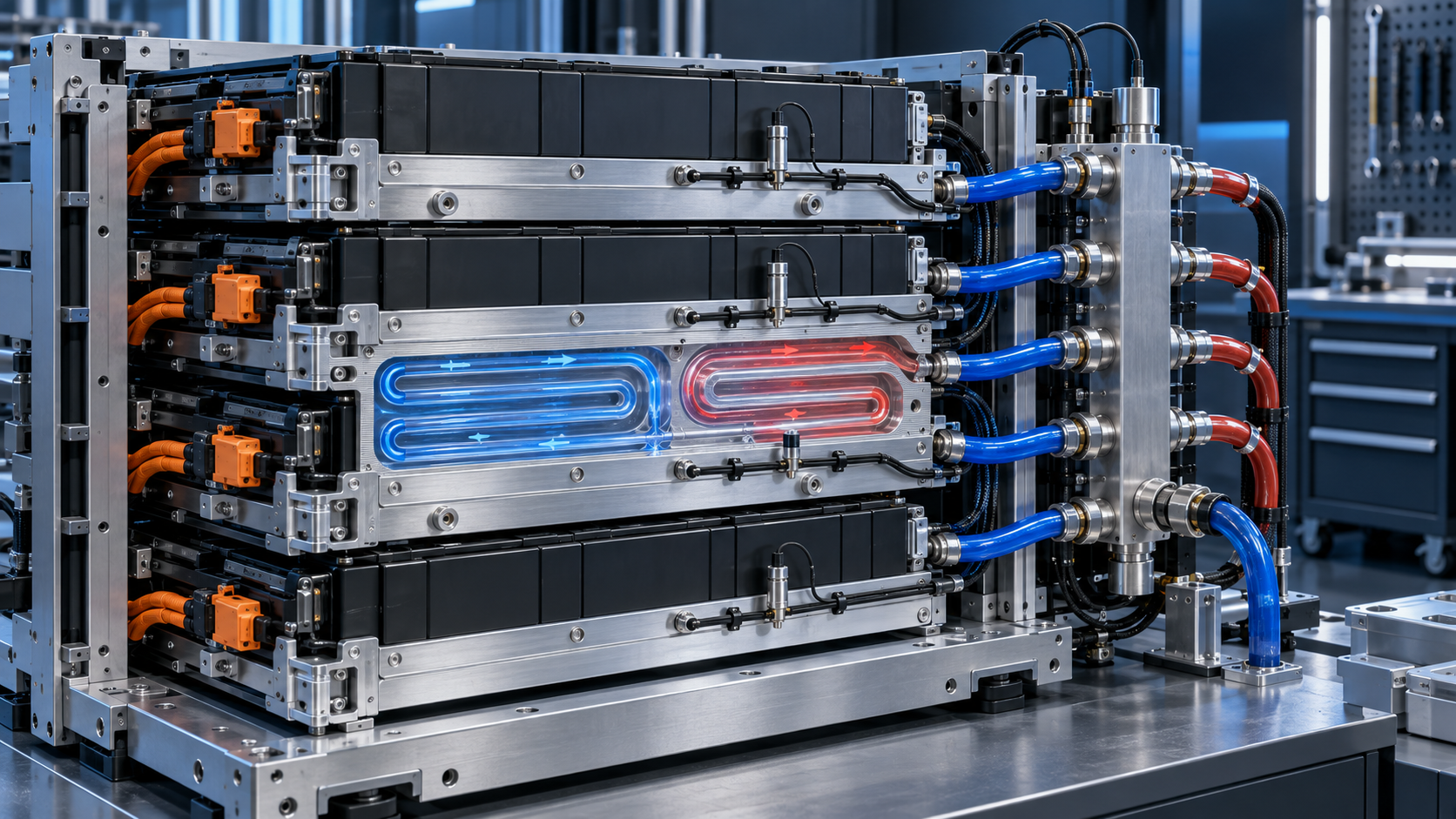
Define the thermal boundary at rack level
Use this sequence before drawing channels:
- Freeze battery and duty inputs. Record chemistry, module heat maps, charge/discharge/standby cycles, temperature limits and ambient range.
- Define the rack hydraulic boundary. State coolant properties, pump curve, available pressure, flow range, branch layout and degraded modes.
- Allocate thermal and pressure budgets. Set interface resistance, module uniformity, channel pressure drop and pump-power targets at the same operating points.
- Select plate architecture and process together. Compare machined, extruded, formed, brazed or welded paths with joints, ports, flatness and volume.
- Validate production-representative hardware. Test thermal response, flow balance, leakage, proof strength, cycling, corrosion and fault behavior.
Stationary storage usually contains many modules connected electrically and thermally through a cabinet or container. The relevant problem is therefore not one plate at one nominal power. It is the full population of modules, their load distribution, coolant supply condition and the heat rejected by pumps, power conversion and auxiliary equipment.
Build a heat map for representative charge, discharge, balancing and standby cases. Identify the maximum heat, typical operating profile and duration of transients. State where allowable temperature and temperature-difference limits apply: cell, module case, plate interface or coolant. Supplier comparisons are unreliable when they use different sensor locations.
IEC 62933-5-1:2024 frames grid-integrated energy storage safety through hazard identification, risk assessment and mitigation. The preview of IEC 62933-5-2:2020 also identifies thermal-control operation verification as part of BESS life-cycle safety information. Use the applicable standards and editions from the project specification.
Create an input matrix before channel design
| Input | What to provide | Why it matters |
|---|---|---|
| Module | Footprint, mass, heat map, flatness, mounting and allowable contact load | Controls plate area, spreading and structural support |
| Temperature | Minimum, maximum, uniformity target and measurement locations | Defines thermal acceptance and sensor plan |
| Coolant | Fluid chemistry, concentration, temperature, contamination and life | Changes heat transfer, viscosity, corrosion and seals |
| Hydraulics | Rack flow, available pressure, branch count and pump curve | Controls channel dimensions and manifold balance |
| Environment | Ambient range, humidity, altitude, outdoor exposure and storage state | Changes cold start, condensation and heat rejection |
| Safety | Leak detection, electrical isolation, vent-gas path and fault response | Controls routing, barriers, sensors and shutdown logic |
Design channels for heat transfer and pump power
Narrow channels can increase local velocity and convective heat transfer, but they also raise pressure drop and sensitivity to blockage. Wide channels reduce resistance but may distribute flow poorly or leave low-velocity regions. Optimize channel width, depth, number of passes and turns against the available pump head and full loop resistance.
A long serpentine path provides predictable routing but accumulates temperature rise and pressure loss. Parallel channels reduce path length yet require headers that divide flow evenly. Use computational analysis to compare concepts, then correlate it with pressure-drop and thermal tests. Include fittings, hoses, filters, valves, heat exchangers and elevation effects in the system model.
Report pressure drop as a curve over flow and coolant temperature rather than one point. Coolant viscosity can increase at low temperature, making cold-start demand more severe than nominal operation. Establish pump margin without assuming that extra flow is free; pumping energy, noise, erosion and component life can constrain the practical operating range.
Balance flow across modules and racks
In a BESS rack, nominally identical plates may receive different flow because branch lengths, fitting losses, elevation and manifold pressure vary. A low-resistance branch can steal flow from a remote or restrictive branch. Use symmetric routing, reverse-return layouts, calibrated restrictions or active control where justified.
Measure branch flow or infer it through validated pressure and temperature data. Check a fully populated rack, partial population and the allowed isolation states. If modules can be replaced, define how quick connections and service valves affect the hydraulic balance before and after maintenance.
The plate design should tolerate the specified production variation in channels and ports without losing rack-level uniformity. Do not solve a poor manifold by imposing extremely tight plate dimensions everywhere. Allocate pressure-drop tolerances to the features that control distribution.
Control the module-to-plate thermal interface
The heat path includes cell-to-module construction, module case, interface material and the cooling plate. Air gaps caused by flatness, bow or weak clamping can dominate local temperature. Define the contact zone, allowed gap, interface material, compression range, mounting sequence and module support.
Use compliant gap fillers only within their qualified compression and temperature range. Excessive compression can load cells or housings; insufficient compression leaves voids. If the plate also carries module weight, check deflection under the full rack load so contact remains consistent.
Apply functional datums to mounting faces and port locations. BAOSONG’s guide to practical aluminum CNC tolerances explains why flatness, position and inspection setup should follow function. Where used, ASME Y14.5-2018 (R2024) provides a GD&T framework.
Choose the plate architecture and joining process
| Architecture | Useful starting point | Main control |
|---|---|---|
| Machined channels plus cover | Prototype, complex routing and controlled local features | Machining, cover joint and distortion |
| Extruded multiport plate | Repeated straight passages and production volume | Profile tolerance, header joints and cut-end closure |
| Stamped or formed plates | Thin, broad channels at suitable scale | Form depth, joining perimeter and flatness |
| Hybrid plate and manifold | Modular racks with serviceable branch connections | Port loads, seals, flow balance and leak access |
Joining may use brazing, friction-stir welding, laser welding, adhesive sealing or mechanical gaskets depending on materials, geometry and production system. Each route creates different heat-affected zones, distortion, cleanliness and inspection needs. Qualify the process using representative coupons and completed plates.
Extruded blanks can reduce machining when channels repeat along a constant section. Review BAOSONG’s aluminum extrusion services, custom extrusion design guide and extrusion plus CNC machining guide before fixing profile walls, ports and secondary datums.
Specify aluminum, coolant and corrosion as a system
State alloy, temper and product form for every plate and fitting. Thermal conductivity matters, but weldability, braze response, strength, flatness, extrusion feasibility and corrosion can control the final choice. Do not transfer a property value from sheet to an extrusion or welded assembly without checking applicability.
Coolant chemistry, dissolved ions, oxygen, temperature and mixed metals determine corrosion behavior. Specify compatible inhibitors, concentration, water quality and maintenance limits. Electrically isolate dissimilar metals where needed and avoid crevices that trap stagnant fluid. Confirm elastomer compatibility with the fluid and life profile.
External anodizing or conversion coating may support corrosion control, but internal treatment and joint compatibility require separate evaluation. Mask thermal contact faces and bonding points as specified. BAOSONG’s surface-finishing overview and anodizing page support early process discussion; the coolant supplier and system integrator must approve the wetted-material set.
Prevent leaks from becoming electrical faults
Place ports, hose joints and manifolds away from exposed high-voltage connections where possible. Use drip paths, shields and sensors so a small leak is detected before fluid reaches energized hardware. Define whether the system drains, isolates a branch or shuts down the rack when leakage is detected.
Support hoses and manifolds independently so connection loads do not bend plate ports. Account for thermal expansion, installation tolerance and service movement. Quick disconnects need qualified sealing, cycle life, residual spill control and correct mating identification.
Pressure and leak tests must reflect the design pressure, temperature and fluid. A gross pressure hold may miss a small leak relevant to long-term operation. Define test medium, proof level, allowable leakage, stabilization, instrumentation and post-test drying or cleanliness.
Manage condensation and cold start
If coolant enters below local dew point, condensation can form on plates, fittings and nearby electrical parts. Evaluate the worst combination of ambient temperature, humidity, door opening and coolant supply. Control coolant temperature, insulate surfaces, manage drainage or seal the environment as the system architecture requires.
Low-temperature coolant raises viscosity and pressure drop. It can also change seal behavior and create differential thermal contraction across aluminum, fittings and module structures. Test startup ramps, not just stable conditions. Define sensor placement and control hysteresis so the system does not hunt around a condensation limit.
Connect normal cooling to BESS safety analysis
UL Solutions’ ESS overview describes UL 9540 as a system evaluation that includes protection, controls, communication and fluid movement. Cooling hardware therefore has to be represented accurately in the certified or evaluated configuration.
UL 9540A evaluates thermal-runaway and fire-propagation behavior at defined test levels. Normal-operation cooling results do not replace this evidence. Conversely, a thermal-runaway test does not establish lifetime cooling uniformity, pump efficiency or corrosion durability.
Define how the thermal-management system behaves during detection, isolation and emergency shutdown. Avoid routing coolant hardware through intended gas or pressure-relief paths. Any claim that cooling changes propagation must be supported by the applicable representative test rather than inferred from normal temperature control.
Validate from component to installed rack
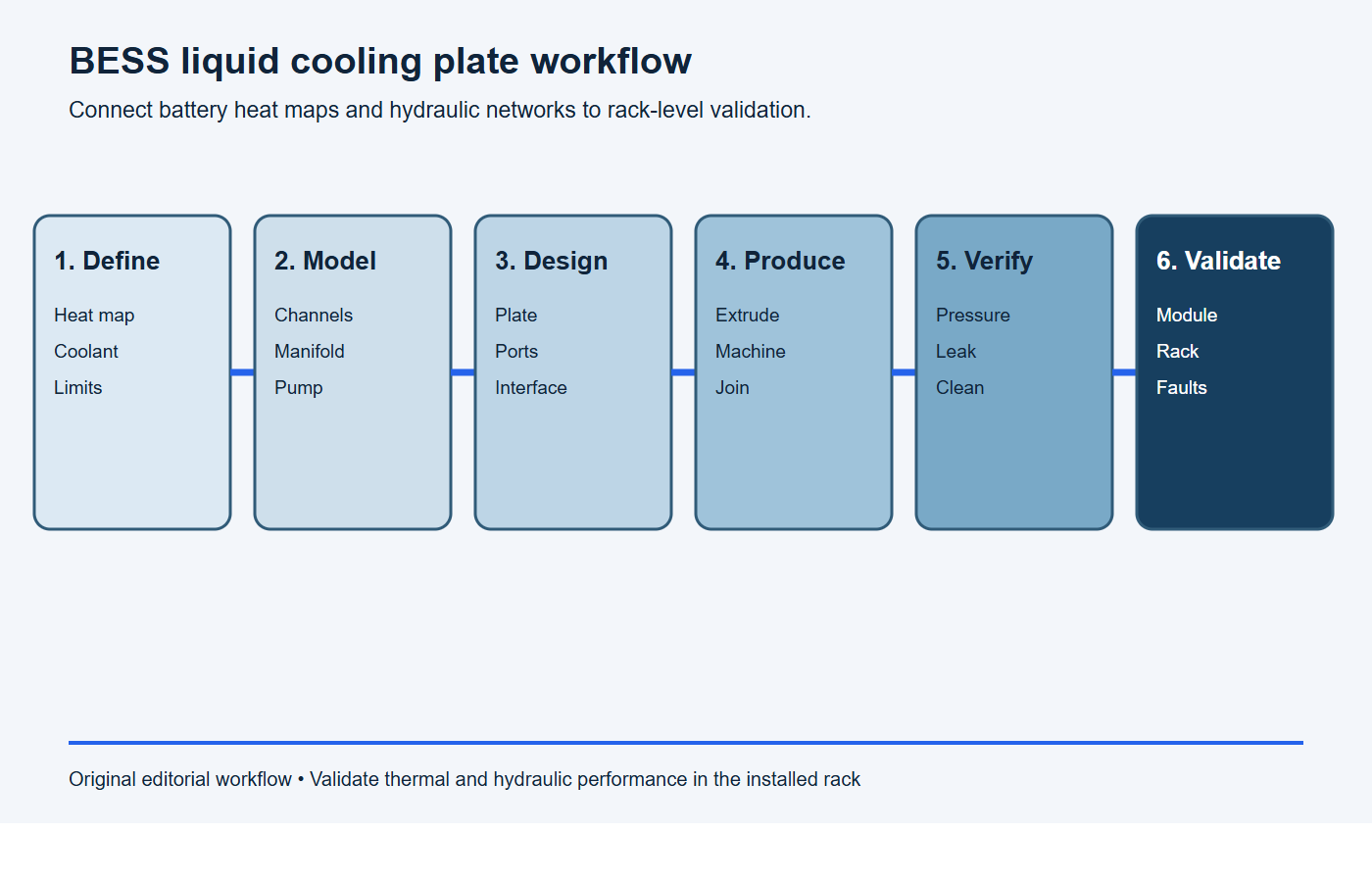
At component level, inspect datums, flatness, channel dimensions where measurable, port position, cleanliness and joint condition. Test pressure drop, proof pressure, leakage and thermal resistance using a defined fixture. Correlate sample destructive sections or nondestructive methods with process controls where internal joint quality is critical.
At module and rack level, measure inlet and outlet conditions, branch flow, cell or module temperatures, plate temperatures and pump power. Test the declared ambient range, charge and discharge profiles, partial population, degraded flow and service states. Record sensor uncertainty and locations with every result.
Thermal cycle, pressure pulse, coolant aging, corrosion, vibration and transport tests should reflect the life profile. Recheck flatness and leakage after durability testing. NIST’s discussion of measurement uncertainty is useful when creating defensible acceptance limits.
RFQ checklist for a BESS liquid cooling plate
Paste this scope into the RFQ and attach the controlled plate drawing, module heat map, rack schematic and validation matrix.
RFQ scope: Please quote [cooling-plate part number and revision] for [prototype quantity] and [annual volume]. The plate supports [battery module and heat map] over [charge/discharge/standby cycles] with target [maximum and uniformity temperatures]. Coolant, inlet range, flow, pump curve, pressure-drop limit and operating/proof pressures are [values]. Quote the proposed aluminum product form, channel architecture, joining, finish, tooling, unit price, lead time and capacity. List every assumption and deviation.
Required evidence: Provide material and wetted-process traceability, dimensional and interface-flatness inspection, flow/pressure-drop and thermal data, leak method and sensitivity, proof or cycle results, cleanliness, port protection, first-article documentation and change-control triggers. Identify rack- and ESS-level safety validation outside the supplier scope.
- Battery chemistry, module geometry, heat map, mass and mounting interface.
- Maximum, minimum and uniformity temperatures with sensor locations.
- Coolant chemistry, concentration, quality limits and operating temperature.
- Rack flow, available pressure, pump curve, branch layout and fault modes.
- Plate alloy, temper, joining process, finish and wetted-material list.
- Ports, fittings, hose loads, leak detection and electrical-clearance zones.
- Datums, flatness, interface material, clamping and inspection method.
- Proof, burst where required, leak, pressure-drop and thermal test conditions.
- Environmental, cycling, corrosion, transport and service-life requirements.
- Prototype and production quantities, traceability and validation plan.
Stop conditions: the BESS cooling plate is not ready for release
Pause tooling or production release if any condition below remains unresolved.
- module heat generation across charge, discharge and standby is missing;
- temperature limits or uniformity targets lack defined sensor locations and operating points;
- coolant, pump curve, branch layout or degraded flow modes are undefined;
- thermal performance and pressure drop have not been evaluated together at rack level;
- TIM, clamping, contact flatness or module tolerance stack is unclear;
- pressure boundary, leak rate, test medium, stabilization or sensitivity is unspecified;
- wetted-material compatibility, cleanliness, corrosion or condensation controls are unresolved;
- normal cooling evidence is being treated as proof of thermal-runaway or complete ESS safety.
Frequently asked questions
Why use aluminum for a BESS liquid cooling plate?
Aluminum combines useful thermal conductivity, low mass and several scalable manufacturing routes. The alloy and construction must also satisfy joining, corrosion, flatness, pressure and electrical-interface requirements.
Is a serpentine channel better than parallel channels?
Neither is universally better. Serpentine paths are easier to balance internally but accumulate pressure loss and coolant temperature rise. Parallel paths reduce length but need carefully designed headers. Compare them within the complete rack loop.
How should leak testing be specified?
State test medium, pressure, temperature, stabilization time, allowable leakage, instrumentation, port condition and post-test cleaning. Match the method to the service fluid, design risk and required detection threshold.
Can liquid cooling prevent thermal runaway?
Liquid cooling can control normal operating temperature and may influence a specific system response, but it does not independently prove prevention or propagation control. Use system hazard analysis and representative UL 9540A or other applicable testing.
Request a BESS cooling-plate manufacturing review
BAOSONG supports aluminum extrusion, CNC machining, joining coordination and finishing. Send the controlled plate model, module heat map, coolant and hydraulic boundaries, ports, interface, inspection requirements, validation plan and quantities through the contact page for manufacturability and quotation review.
Recommended Downloads for Aluminum Alloy Selection
Use these BAOSONG references to compare alloy families, temper conditions, machinability, strength, corrosion resistance and design implications before quotation.
- Aluminum Alloy Comparison Chart (editable Excel)
- Tolerance Reference Guide (PDF)
- Aluminum CNC Machining Design Guide (PDF)
- Aluminum Part Design Checklist (editable Excel)
Need help choosing an alloy or temper for your application? Contact BAOSONG Precision.
