
Quick answer: how does wall thickness affect aluminum extrusion quality and cost?
Aluminum extrusion wall thickness affects metal flow through the die, cooling behavior, dimensional stability, surface consistency, part weight and the production rate a supplier can use. Relatively balanced neighboring walls usually give the process a more stable starting condition. Abrupt thick-to-thin changes make flow and cooling harder to balance and can increase die correction, straightening, sorting or downstream machining.
Thinner is not automatically cheaper. Reducing metal lowers weight per length, but a thin or slender wall may require a more demanding die feature, slower processing, wider feasible tolerances or extra handling protection. A thicker wall uses more aluminum and can increase part weight, yet it may be easier to extrude than an aggressively thin section. Total cost depends on material mass and process difficulty together.
Select wall thickness from structural, thermal, fastening, finishing and machining requirements, then review the complete cross-section with the intended extruder. There is no universal minimum that applies to every alloy, temper, profile size, wall length, hollow, tolerance and surface requirement.
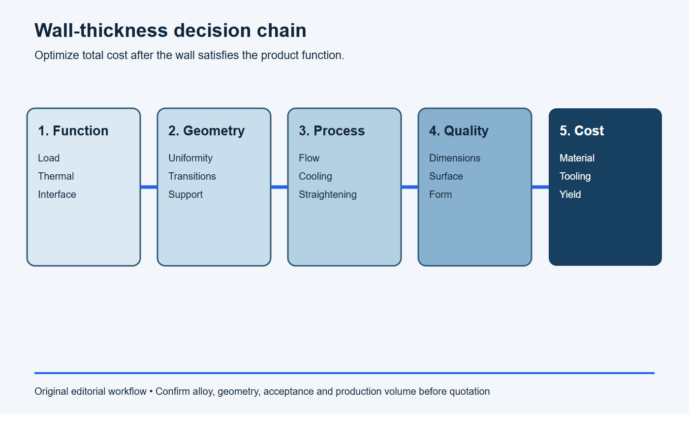
Use this wall-thickness review before changing the profile
- Mark the function: identify which walls carry load, transfer heat, hold fasteners, protect components or provide machining stock.
- Compare the neighbors: find abrupt thick-to-thin changes, long unsupported walls, heavy bases and thin features around hollows.
- Test the alternatives: compare material mass, die difficulty, process rate, tolerances, handling and later machining together.
- Verify the release: obtain supplier feedback on the controlled section and approve representative samples against measurable requirements.
Wall thickness controls resistance to metal flow
During extrusion, aluminum must fill all regions of the die opening and emerge as one continuous profile. Thick and thin regions do not present the same flow condition. When a heavy base sits beside thin webs or fins, the die designer must manage unequal resistance so the profile exits at a compatible speed across the section.
The Aluminum Extruders Council advises designers to keep wall thicknesses uniform where practical and warns that thick-thin junctions can contribute to distortion, die problems or surface defects. These are design guidelines rather than absolute acceptance limits. Modern tooling can produce complex sections, but the geometry, alloy, press and economic target must be evaluated together.
| Wall condition | Possible process effect | Design question |
|---|---|---|
| Balanced neighboring walls | More compatible flow and cooling conditions | Can the function be met without an abrupt local mass change? |
| Thin long wall or fin | Higher flow resistance, fragile die support and handling sensitivity | Is the thickness required for weight or thermal performance, and over what length? |
| Heavy base beside thin features | Unequal flow and thermal response across the section | Can mass be redistributed, transitioned gradually or separated into parts? |
| Wall around an enclosed void | Wall variation or eccentricity may need separate tolerance treatment | Which local thickness protects function, and how will it be measured? |
Uniform walls support more predictable cooling and shape
The profile continues to change after it leaves the die. Thin regions and heavy regions exchange heat differently, while asymmetric material distribution can create uneven contraction. The result may appear as bow, twist, flatness variation or contour change. Stretching and straightening can help control form, but they do not eliminate the need for a sound section design.
Uniformity should be judged locally and functionally. A profile does not need one identical thickness everywhere. A structural flange may justifiably differ from a protective cover wall. The design task is to avoid unnecessary contrast and to use smooth transitions where different thicknesses are required.
Thin walls can reduce weight but increase process difficulty
Thin walls are useful when low mass, compact size, thermal fins or material efficiency are important. Their cost effect depends on whether the geometry lets the supplier produce them at a stable rate. A short supported wall is different from a long unsupported panel. A thin wall in a compact symmetric profile is different from a thin feature at the end of a deep channel.
Potential consequences of an aggressive thin-wall design include:
- greater sensitivity to die support and bearing design;
- reduced feasible extrusion speed for the selected alloy and section;
- more sensitivity to handling, cutting, clamping or transport damage;
- wider practical form or wall-thickness variation;
- additional trials, die correction or inspection;
- insufficient stock for a later machined surface.
Do not choose a minimum wall from a generic chart before checking its conditions. Supplier-specific examples may reflect one press range, alloy family, circumscribing circle and tolerance expectation. Treat those numbers as screening information, then request confirmation against the released geometry.
Thick walls add material and may simplify production
A thicker section generally increases mass per length and therefore material cost. It can also increase finished-product weight, which may affect shipping, assembly or system performance. But a thicker wall is not necessarily harder to extrude. The AEC notes that very thin walls can be costly to produce, while thicker walls may support more efficient processing in some profiles.
Extra thickness may be justified for load capacity, fastener engagement, thread depth, impact resistance, heat spreading, machining allowance or robust handling. It becomes waste when it serves no defined function. Use structural or thermal analysis where appropriate, and separate safety or stiffness requirements from a habit of making every wall heavy.
Abrupt thickness transitions can affect surface and dimensional quality
A thick-thin junction changes the local flow path and thermal mass. If the transition is abrupt, the die and process must compensate over a short distance. This can contribute to surface variation, local contour change or difficulty maintaining adjacent dimensions. Appearance-sensitive faces can reveal flow-related or finishing differences more readily than hidden structural areas.
Use a radius, taper or blended transition when the mating envelope allows it. The exact transition is project-specific; it depends on wall sizes, die construction, surface class and product function. A visually sharp corner may be replaced by a small permitted radius, a relief in the mating part or local CNC machining if the interface truly requires it.
Wall thickness interacts with ribs, fins and deep channels
A thin wall becomes more challenging when it forms a tall fin, deep narrow channel or slender tongue in the die. The issue is not the thickness number alone. Aspect ratio, root support, channel opening, wall length and the surrounding mass determine the mechanical and flow condition.
For a heat sink, thinner fins can increase fin count within a fixed envelope, but thermal performance also depends on fin height, spacing, airflow, base spreading and interface resistance. The most extrudable fin is not automatically the best thermal system, and the thinnest fin is not automatically the most economical. Review thermal analysis and die feasibility together.
For structural channels or rails, ask whether the deep feature must be continuous. A local slot can often be machined. An enclosure may use an open extrusion plus a cover instead of a difficult enclosed or nearly enclosed space.
Hollow profiles need wall and eccentricity review
A hollow profile contains an enclosed void and uses a tooling route that brings metal around die supports before it rejoins. The wall surrounding the void may not vary in the same way as a simple open web. The applicable product standard can treat wall thickness that completely encloses a space through specific notes or eccentricity provisions.
The Aluminum Association identifies ANSI H35.2-2024 as the dimensional-tolerance standard for aluminum mill products. Its extrusion tolerance guidance distinguishes metal and space dimensions for solid and hollow profiles. Use the current standard, correct product category, alloy and temper instead of transferring a tolerance from an unrelated profile.
Wall thickness affects more than wall-thickness tolerance
A drawing may control a wall locally, yet the section also has overall width and height, channel openings, angularity, contour, flatness, straightness and twist. Tightening only the nominal wall tolerance does not necessarily improve the functional assembly. A broad panel may still need flatness control, and a long rail may still need straightness and twist limits.
Connect each requirement to a buyer or engineering decision:
- minimum structural section for load;
- minimum stock remaining after profile variation and machining;
- maximum wall that still allows a mating component to fit;
- surface form needed for sealing, mounting or appearance;
- profile weight or thermal response needed by the system.
For downstream features, see BAOSONG’s aluminum CNC machining tolerance guide. It addresses the separate dimensional controls used after the profile has been extruded and fixtured for secondary machining.
Wall thickness changes the cost model in several ways
The quotation is not a simple price per kilogram calculation. Wall thickness influences several cost drivers at the same time:
The AEC’s key design considerations identify both profile weight and shape constraints as economic factors. A useful quotation therefore needs the complete section and production requirements, not wall thickness in isolation.
| Cost driver | How wall thickness contributes | Information needed for quotation |
|---|---|---|
| Material | Changes profile area, weight per length and purchased metal | Controlled section, alloy, temper, cut length and quantity |
| Tooling | Thin walls, deep channels and abrupt transitions may require more demanding support and correction | 3D model, dimensioned cross-section and critical characteristics |
| Press productivity | Flow resistance and thermal limits may affect feasible production rate | Alloy, profile size, surface class and acceptance requirements |
| Yield and inspection | Difficult walls or form requirements can increase sampling, sorting or nonconforming risk | Tolerance standard, methods, reporting and lot requirements |
| Secondary operations | Insufficient or excessive stock changes machining time and fixture strategy | Finished datums, machining drawing and pre/post-finish condition |
A lower profile weight can reduce recurring material cost, but it should be compared with tooling effort, rate, yield, handling and later operations. Without controlled geometry, annual volume and acceptance criteria, a credible savings percentage cannot be stated.
Choose wall thickness from function before cost reduction
Start with the product rather than an extrusion rule. Structural walls need load cases, spans, joint details, permitted deflection and safety requirements. Thermal profiles need heat load, allowable temperature, airflow, orientation and interface information. Enclosures need impact, sealing, electromagnetic, fastening and cosmetic requirements. Machined profiles need minimum stock around final datums and features.
Then compare candidate sections. Moving material away from the neutral axis may improve bending stiffness more efficiently than thickening the whole profile. A rib may support a panel with less mass than a uniformly heavy face. A hollow can improve torsional behavior but changes tooling and tolerance considerations. Validate the actual result using appropriate analysis, samples and assembly tests.
Plan CNC machining allowance around expected variation
A machined pad, bore or sealing face needs enough local material after the worst acceptable profile variation and fixture setup are considered. Nominal stock alone is insufficient. Define the as-extruded datum strategy, final machined datum system and the surface from which material will be removed.
A very thick machining pad can add recurring material and cutting time. A pad that is too thin risks incomplete cleanup. Coordinate the extrusion drawing with the finished-part drawing and locate local features from functional datums. See BAOSONG’s aluminum CNC milling information when planning secondary operations.
Account for anodizing and cosmetic surfaces
Wall design can influence visible contour and surface uniformity, while surface treatment adds its own dimensional and appearance conditions. Mark cosmetic faces, contact or masking areas, threads, sliding fits and sealing regions. State whether a controlled dimension applies before or after finishing.
Do not use a tighter wall tolerance as a substitute for an appearance standard. Define acceptable die lines, handling marks, gloss and color comparison separately. BAOSONG’s anodized aluminum and surface finishing pages provide a starting point for that review.
How to review wall thickness before tooling release
- Mark the function of every wall, rib, fin, boss and machining pad.
- Identify unnecessary mass and unnecessary thin regions.
- Compare neighboring thicknesses and blend required changes gradually.
- Review symmetry, hollows, deep channels and slender die features.
- Confirm the alloy, temper, circumscribing circle, weight per length and surface class.
- Separate extrusion-controlled dimensions from CNC features.
- Define wall, flatness, straightness and twist requirements independently.
- Agree on datums, support conditions, instruments and sampling.
- Evaluate cut-off, finishing, machining, assembly and packaging.
- Compare total cost and approve representative samples against the controlled drawing.
Where geometric tolerancing is used, cite the applicable drawing standard. ASME Y14.5-2018 (R2024) defines dimensioning and GD&T rules, while the extrusion-product standard remains responsible for its own tolerance categories. Do not mix their roles without a clear inspection plan.
Stop conditions: do not release the wall change yet
- The wall was thinned only to reduce material cost without checking stiffness, heat flow, fastening or handling.
- The revision creates an abrupt mass change, deep tongue or hollow-wall condition that the intended extruder has not reviewed.
- A machining pad may not clean up across expected profile variation and fixture location.
- The cost comparison includes aluminum weight but omits die development, rate, straightening, inspection, scrap and secondary work.
- The drawing lacks an agreed wall measurement method, product standard, finished condition or sample acceptance plan.
Copy-ready wall-thickness review request
Please review profile [part number/revision] for wall-thickness optimization at [length and quantity]. The function of each marked wall is [load, heat transfer, fastening, enclosure, finish or machining stock]. Compare the current and proposed sections for weight per length, metal-flow balance, die support, expected rate, tolerance, straightening, finish, handling and secondary machining. Identify the lowest-risk change, the dimensions that need project-specific control and the representative sample evidence required before approval.
Frequently asked questions
What is the minimum wall thickness for an aluminum extrusion?
There is no universal minimum. It depends on alloy, temper, profile size, wall length, shape complexity, die support, tolerance, finish, press capability and production economics. Ask the intended supplier to assess the controlled cross-section.
Does making every wall thicker improve extrusion quality?
No. More thickness can simplify some thin features but adds mass and may worsen imbalance if applied locally. Use the thickness needed for function and aim for compatible neighboring sections with gradual transitions.
Why can a thinner extrusion cost more per kilogram?
An aggressively thin profile may need more demanding tooling, slower processing, additional development, inspection or handling even though it contains less metal. Compare finished-part cost rather than material weight alone.
Can wall thickness variation be corrected by CNC machining?
Machining can establish local surfaces and dimensions when enough stock remains, but it is usually inefficient for correcting an entire long profile. Improve the section and extrusion controls first, then machine only the features that need finished-part precision.
Request a wall-thickness and cost review
BAOSONG supports projects combining custom aluminum extrusion, machining and finishing. Review the available engineering support and quality approach, then send the controlled drawing, model, alloy and temper, critical walls, finish, machining features, inspection requirements and production quantity through the contact page for engineering review and quotation.
Recommended Downloads for Aluminum Extrusion Design
Use these BAOSONG references to set profile geometry, wall thickness, tolerances and downstream CNC features before releasing an extrusion design.
- Custom Aluminum Extrusion Design Guide (PDF)
- Wall Thickness and Tolerance Guide (PDF)
- CNC Machining Guide for Aluminum Extrusions (PDF)
- Aluminum Alloy Comparison Chart (editable Excel)
Need help checking an extrusion profile or manufacturability risk? Contact BAOSONG Precision.
