
Quick answer: should you use extrusion, CNC machining or die casting?
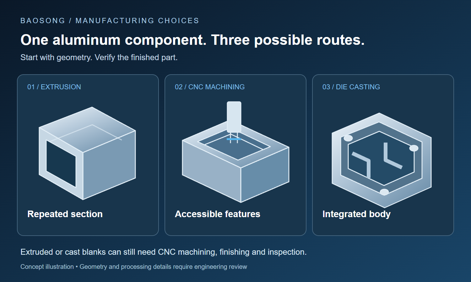
Start with extrusion when the main shape repeats along its length, CNC machining when accessible features and design flexibility drive the project, and die casting when a stable three-dimensional design can justify dedicated production tooling. Compare the complete route—including machining, finishing and inspection—to the same finished-part requirements.
These choices often work together. An extruded housing may need accurately located connector openings. A die-cast enclosure may need machined threads and mating faces. The useful decision is how to create the bulk shape economically while controlling the interfaces that make the assembly work.
This guide focuses on hot aluminum profile extrusion, CNC milling and turning, and high-pressure aluminum die casting. Other casting methods, forging and sheet-metal fabrication may be worth evaluating when these routes do not suit the design.
Seven-step process selection guide
| Step | Action | Decision output |
|---|---|---|
| 1 | Define function, loads, environment, appearance and critical interfaces | Prioritized requirements |
| 2 | Classify the geometry as repeated section, tool-accessible solid or integrated 3D body | Shortlisted processes |
| 3 | Assign each feature to forming, machining, finishing or assembly | Feature responsibility map |
| 4 | Compare material and finish options for each route | Technically feasible routes |
| 5 | Quote tooling and variable cost for the same accepted finished part | Equivalent cost comparison |
| 6 | Review design stability, forecast and change risk | Investment decision |
| 7 | Build and inspect representative parts | Released production route |
Aluminum extrusion vs CNC machining vs die casting
Use the comparison below to shortlist candidates. It is a planning guide, not a universal tolerance or order-quantity specification.
| Decision factor | Extrusion + fabrication | CNC from stock | Die casting + finishing |
|---|---|---|---|
| Geometry to investigate | A repeated cross section: rails, channels or long housings. | Pockets, bores and faces that cutting tools can reach. | A three-dimensional body with integrated walls, ribs and bosses. |
| Initial investment | Custom die if needed; cutting and machining fixtures. | Programming, setup and workholding; no dedicated shape-forming die. | Casting die, possible slides and trim tooling, plus validation. |
| Design changes | Length changes may reuse the profile; section changes can affect the die. | Assess toolpaths, stock and fixtures when features change. | Changes may require die modification or replacement. |
| Critical features | Define which features remain as extruded and which are machined. | Plan datums and setups around functional relationships. | Separate as-cast requirements from machined requirements. |
| Main economic question | Does the profile eliminate enough material removal or assembly? | How much machine time and material removal does each part require? | Can realistic repeat demand recover the added tooling and validation cost? |
Step 1: prepare the decision inputs
Complete this list before asking suppliers to recommend a process:
- part function, loads and expected life;
- operating temperature, moisture, chemicals and sealing requirements;
- critical datums, fits, threads, bores and mating faces;
- visible surfaces, texture, coating and color acceptance;
- prototype quantity, annual demand and total expected demand;
- design-freeze date and likely future changes;
- assembly operations and opportunities to combine parts;
- inspection, traceability, approval and packaging requirements.
If the volume or design is uncertain, request more than one route. Ask suppliers to state their assumptions instead of hiding them inside a single price.
Step 2: let the geometry narrow your options
Extrusion: create the repeated section first
Extrusion forces solid material through a die to form an extended section, which can then be cut to length. Unlike die casting, its primary shape follows a repeated cross section. NADCA explains this distinction in its comparison of extrusion and die casting.
Think of a sensor rail with a cable channel running along its length. The profile can incorporate that channel continuously; holes or local openings can be added later. Ask whether the design can use an existing section before commissioning a custom one.
For custom aluminum extrusions, submit the cross section and finished part together. The Aluminum Extruders Council’s design guidance highlights wall transitions, symmetry and visual surfaces. A shape that looks economical in a CAD model still needs review for extrusion and subsequent operations.
CNC machining: check access, not just complexity
CNC milling and turning remove material with controlled cutting tools. A part can start as stock or as a preformed blank. A milling cutter needs access to the feature, while turning is especially useful for features organized around a rotational axis.
For a mounting block with pockets and locating bores, ask how the part will be held and how many setups establish its critical relationships. A complex appearance alone does not tell you whether machining is straightforward.
Protolabs’ machining design guidance identifies tool access, deep features and undercuts as practical constraints. Its published service limits belong to that supplier; they are not universal CNC limits. For your CNC machining project, review the actual geometry instead of relying on a generic precision claim.
Die casting: design for filling and release
High-pressure die casting injects liquid metal into a reusable steel die. It can integrate features such as ribs and mounting bosses into a three-dimensional body. The North American Die Casting Association’s process overview describes the process and its design resources.
A casting must both fill and leave the die. The parting line, ejection arrangement and any slides belong in the design review. NADCA’s draft guidance explains why the required taper varies with the surface, depth and alloy. Do not apply one arbitrary draft angle to every wall.
Bring a stable model and a realistic production forecast to an aluminum die casting review. Ask the supplier to identify changes needed for the proposed casting route before approving tooling.
Step 3: assign every critical feature to an operation
“High precision” becomes useful when it identifies what must fit, align, seal or move. A broad process tolerance tells you little about a locating bore’s relationship to a mounting face.
Mark the functional datums and identify the features that control assembly. Then agree which manufacturing operation establishes each one. Keep general dimensions separate from the critical requirements; tightening every dimension can add cost without improving function.
- Extrusion: distinguish the original section dimensions from later machined holes and faces.
- CNC: review how workholding, access and setup changes affect the required relationships.
- Die casting: distinguish dimensions formed by the die from those established by finish machining.
For each critical characteristic, specify its acceptance condition, measurement approach and required record. If a coating affects a fit, state whether the requirement applies before or after finishing. Use a component inspection plan that follows the drawing rather than a list of impressive equipment names.
Step 4: compare complete routes, including secondary machining
Near-net shape means the blank approaches the finished geometry. It does not mean every feature is complete. NADCA’s secondary-processing guidance includes trimming, machining and finishing as operations that can follow die casting.
For an enclosure, compare three actual routes:
- Stock → CNC → finish: create the body and interfaces by machining.
- Extrusion → cut → CNC → finish: retain the repeated profile and machine local details.
- Die casting → trim → CNC where needed → finish: form the integrated body and finish selected interfaces.
Ask for a feature map showing the operation responsible for each critical dimension. This reveals whether a low-cost blank creates expensive finishing work. It also helps avoid paying to form a feature that will immediately be removed.
| Feature | Created by | Finished by | Inspection and risk |
|---|---|---|---|
| [outer body or section] | [extrusion, casting or stock] | [as formed or machining] | [method and open risk] |
| [datum surface] | [operation] | [operation] | [method and setup] |
| [critical bore or thread] | [operation] | [operation] | [gage/CMM and reaction] |
| [sealing face] | [operation] | [operation/finish] | [flatness, texture or leak test] |
| [visible surface] | [operation] | [surface finish] | [visual standard and handling] |
For repeated profiles, CNC machining after extrusion is a distinct route worth quoting. The AEC’s custom-extrusion white paper notes that fabrication tooling and inspection fixtures can become significant. Its historical price examples should not be used as current project quotations.
Step 5: use quantity and design stability together
There is no universal quantity at which die casting automatically becomes cheaper than machining. A simple turned component and a deeply pocketed enclosure do not have the same economics.
Start with quantities that the program can credibly support: samples, launch demand and repeat orders. Separate annual demand from total demand over the expected design life. Then ask what happens if demand is lower or the design changes.
For each route, request separate figures for tooling, programming, fixtures, validation, finished-part price and delivery batches. Include tool ownership, maintenance and revision terms in the comparison. A low recurring price may be attractive only after the fixed investment is recovered.
A simple break-even calculation
For an initial comparison, let total cost = fixed cost + quantity × variable cost per accepted part. Use the same delivered scope and currency for every route.
The following numbers are deliberately hypothetical. They are arithmetic inputs, not BAOSONG prices or industry benchmarks.
| Assumed input | Route A: machined stock | Route B: tooled blank + finishing |
|---|---|---|
| Fixed cost | USD 2,000 | USD 20,000 |
| Variable cost per accepted part | USD 40 | USD 25 |
| Total at 1,200 parts | USD 50,000 | USD 50,000 |
The crossover is (20,000 − 2,000) ÷ (40 − 25) = 1,200 parts. Below that quantity, Route A has the lower modeled total; above it, Route B does. This result belongs only to these assumptions.
Replace the inputs with quotations, then test lower demand, tooling changes and additional inspection costs. The simple model assumes constant unit costs and excludes financing and timing effects. It cannot choose the technically suitable process for you.
Step 6: check material, appearance and sealing requirements
Changing the process may change the material specification. A machined prototype made from wrought stock is not proof that a production casting will have the same properties. NADCA’s aluminum-alloy guidance addresses cast-alloy choices; review those against the design requirements rather than carrying a wrought-alloy callout across unchanged.
For a wrought-stock or extrusion route, our 6061 vs 6063 aluminum guide explains why temper and product form matter. Select the manufacturing route and material together.
For visible parts, approve the actual substrate, preparation and finish as a combination. Identify appearance-critical surfaces, acceptable tool or process marks and the reference sample. Do not assume the same coating name guarantees the same appearance across different alloys and routes.
Compare the complete surface-finishing route, including preparation, masking, coating state and final inspection, rather than treating finish as an identical add-on for every manufacturing process.
For sealed components, define the leak-test medium, pressure, acceptance limit and test stage. Machining is not proof of leak tightness, and it does not by itself eliminate casting porosity. NADCA describes specialized die-casting variants intended to reduce gas porosity; their suitability still needs project-specific verification. Validate the finished component in its required condition.
Step 7: validate the route with representative parts
Build samples through the proposed material, tooling, forming, machining, finishing and inspection route. Record every deviation from production intent. Review all parts, including scrap and rework, rather than only selected good samples.
Use the following three hypothetical scenarios to see how requirements change the starting route. They are decision examples, not BAOSONG customer cases.
A sensor rail offered in several lengths
Starting point: investigate extrusion because the cable channel and mounting section repeat. Cut different lengths and machine local mounting features. Check: whether one section works across the product family, and whether cut-end features need separate setups. Validate: the assembled rail, including straightness and mounting alignment.
A mounting block still undergoing design changes
Starting point: investigate CNC from available stock to evaluate the evolving interface geometry. Check: tool access, fixtures and how much material must be removed. Validate: fit and functional loads. Keep a record of revisions so the production-route comparison uses the final design.
An electronics housing with stable repeat demand
Starting point: compare die casting plus selected machining against an extruded body with end covers and a fully machined alternative. Check: tooling recovery, assembly count, sealing interfaces and finish acceptance. Validate: production-representative samples; a machined prototype alone cannot validate casting-specific behavior.
Production-route release checklist
- The model, drawing and specification revisions agree.
- The selected material belongs to the proposed product form and process.
- Every critical feature has an assigned manufacturing and inspection operation.
- Tooling, fixture, programming and validation costs are included.
- Quotations cover the same finish, inspection, packaging and delivery scope.
- Representative samples use the intended production route.
- Critical dimensions are checked in the required finished condition.
- Appearance, sealing, assembly and functional requirements are verified.
- Trial yield, scrap, rework and process adjustments are recorded.
- Open technical risks have owners and due dates.
Stop conditions: do not release tooling or production
- The supplier selected a route without reviewing the drawing and annual demand.
- The die-cast material is assumed to match wrought prototype properties.
- As-extruded, as-cast and machined tolerances are mixed together.
- A critical feature has no defined datum or inspection method.
- The quotation excludes required finishing, secondary machining or inspection.
- The design is still changing but dedicated tooling is treated as fixed.
- Sealing or cosmetic performance is assumed without a finished sample or test.
- Only selected good samples are shown and the real trial yield is unknown.
What to send for a useful manufacturing review
Provide the drawing and 3D model with the same revision, the part’s function, critical interfaces, material requirements, finish and inspection expectations. Add sample quantities, realistic repeat demand and the date by which the design is expected to stabilize.
Ask each supplier to return a proposed route, required design changes, tooling scope, critical-feature plan and a quotation for the same finished deliverable. Early engineering review should resolve open requirements before dedicated tooling is released. That makes the decision reviewable.
Copy-ready supplier request
“Please review the attached [part/revision] for [prototype quantity], [annual demand] and [expected program demand]. Compare CNC from stock, extrusion plus CNC and die casting plus secondary machining where feasible. Return a marked-up DFM, process route, material proposal, feature responsibility map, tooling and fixture costs, finished-part price, validation plan, inspection records and open risks. Quote every option to the same finished, inspected and packaged condition.”
At BAOSONG, we welcome your drawings and requirements for an engineering review. Tell us what the component must do, and we can discuss the extrusion, machining or casting route to evaluate for your project.
Frequently asked questions
Is CNC machining only suitable for prototypes?
No. It can remain a production route when geometry, quantity and finished-part requirements support the cost. Compare actual quotations rather than ruling it out because a project has moved beyond prototyping.
Does die casting eliminate machining?
Sometimes a casting needs little additional work, but threads and critical interfaces can require secondary operations. Identify those features before comparing the cost of a casting with a finished machined part.
Can one extrusion serve multiple product lengths?
Potentially, if the same cross section satisfies each version. Cutting length may change without changing the profile die, but local openings, end machining and inspection requirements still need review.
Which route gives the best precision?
Define the feature and its acceptance criteria first. CNC may establish a critical interface on either an extruded or cast blank. The complete process and inspection plan must demonstrate that the finished requirement can be met.
Recommended Downloads for Aluminum Process Selection
Use these BAOSONG references to compare extrusion, die casting and CNC machining, then align material, geometry, tolerances and post-processing requirements.
- Custom Aluminum Extrusion Design Guide (PDF)
- Aluminum Die Casting Design Guide (PDF)
- Aluminum CNC Machining Design Guide (PDF)
- Aluminum Alloy Comparison Chart (editable Excel)
Need help selecting the right manufacturing route? Contact BAOSONG Precision.
