
Quick answer: what should engineers specify for an aluminum charging station enclosure?
Specify the enclosure from the charger architecture, installation environment and target product standard. The essential inputs are heat dissipation and allowable component temperatures, indoor or outdoor exposure, solar load, ingress and impact targets, cable and door interfaces, corrosion environment, service access, appearance zones and the required verification state. An aluminum shell can conduct heat and carry seals, but it does not by itself establish an IP rating or certify the charging equipment.
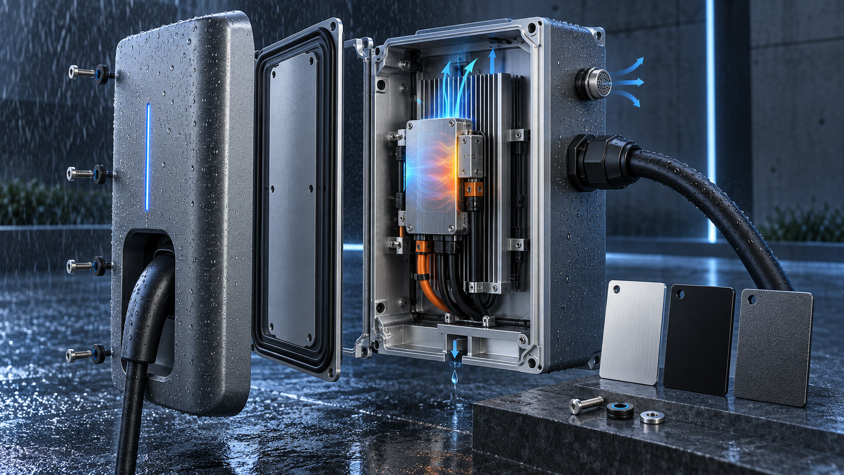
Create a continuous thermal path from power electronics to ambient air while keeping water, dust and condensation away from electrical interfaces. Treat panels, heat spreaders, thermal interface materials, fins, vents, gaskets, fasteners and coatings as one system. Test the fully assembled enclosure with production-equivalent doors, glands, vents and hardware.
Choose extrusion, sheet fabrication, die casting and CNC machining by geometry and volume. Then specify finish by exposure and appearance: alloy, pretreatment, coating system, color and gloss range, acceptable variation, masked electrical contacts, rack points and test method. Keep the drawing measurable and connect every tight requirement to thermal, sealing, structural, electrical or cosmetic function.
Start with charger type, location and compliance route
Use this five-step sequence before selecting wall thickness or finish:
- Define the installation. Record charger type, contained equipment, destination market, indoor or outdoor location, service access and environmental exposure.
- Set measurable system targets. Specify heat losses, temperature limits, ingress and impact requirements, corrosion exposure and appearance zones.
- Build the architecture. Establish heat paths, wet and dry zones, doors, gaskets, vents, glands, drainage, grounding and structural load paths.
- Select manufacturing and finish together. Compare extrusion, sheet, casting and CNC routes with joint count, volume, tolerances, alloy, pretreatment and coating.
- Validate the complete assembly. Test production-equivalent doors, seals, vents, cables, hardware and finishes in the required mounted condition.
An AC wallbox and a high-power DC charger place different demands on an enclosure. The AC unit may house switching, metering, communications and protection components with modest heat loss. A DC charger can contain power modules, busbars, filters and liquid-cooling hardware, or split these functions among a dispenser and a separate power cabinet. Define what the enclosure actually contains before choosing its construction.
Record installation orientation, indoor or outdoor use, ambient temperature range, altitude, humidity, rain, wind-driven dust, salt or industrial contaminants, ultraviolet exposure, snow and ice, cleaning method, vandalism risk and service frequency. Include the cable loads, connector holster, door swing, foundation or wall interface and accessibility constraints.
IEC 61851-1:2017 covers general requirements for conductive EV supply equipment. In North America, UL identifies ANSI/UL 2594 for EV supply equipment and ANSI/UL 2202 for DC charging equipment among the relevant standards. The applicable edition and full certification plan depend on charger type and destination market. Confirm them with the product compliance body early.
Convert system needs into an enclosure requirement matrix
| Requirement | Design questions | Enclosure features | Evidence at release |
|---|---|---|---|
| Thermal | Where is heat generated, and what limits junction, air and touch temperatures? | Spreaders, interface pads, fins, ducts, fans or liquid-loop mounts | Correlated analysis and worst-case thermal test |
| Ingress | Which solids and water exposures apply in the installed orientation? | Seam geometry, gaskets, glands, vents, drains and door hardware | Assembled IP or product-standard test |
| Impact and structure | What loads come from handling, cables, users, wind and misuse? | Wall sections, ribs, hinges, latches, mounts and guarded interfaces | Load, impact and transport validation |
| Electrical interfaces | Where are bonding, insulation, creepage and cable boundaries? | Masked contacts, studs, partitions, gland plates and controlled edges | Product safety evaluation and continuity tests |
| Corrosion | Are salt, moisture, cleaners or dissimilar metals present? | Alloy, finish, drainage, isolation and sealed joints | Project-specific corrosion exposure and inspection |
| Appearance | Which surfaces are customer-visible, and under what light? | Finish sample, texture, color/gloss window and protected handling | Approved boundary sample and visual inspection |
| Service | Which parts must be reached, replaced or cleaned? | Door access, captive hardware, labels and repeatable gasket compression | Service trial and closure-cycle test |
This matrix prevents one headline value, such as IP66, from hiding other failure modes. A sealed cabinet may still overheat, trap condensate, corrode at fasteners or lose gasket compression after repeated servicing.
Design the complete thermal path
Begin with component loss data and allowable temperatures. Map conduction from each heat source through its baseplate, thermal interface material, aluminum spreader and enclosure wall to fins or a cooled plate. Add contact resistance, coating interruptions, fastener preload and manufacturing flatness. Aluminum’s bulk conductivity is only one term in this chain.
Passive systems use natural convection and radiation and avoid fan openings, but they need sufficient surface area and orientation. Forced-air systems increase heat transfer but introduce filters, fan life, noise and maintenance. A separated-air architecture can circulate internal air across electronics and reject heat through an external heat exchanger without exchanging ambient air. High-power units may require liquid cooling and leak management.
Run analysis across component tolerance, fan or pump degradation, fouling, altitude and ambient extremes. Instrument prototypes at heat sources, interface boundaries, internal air, external surfaces and inlet/outlet locations. Correlate the model to test data before using it to qualify variants.
For an overview of integrated cold plates, channels and leak boundaries, see BAOSONG’s guide to aluminum liquid cooling plates. For heat-dissipating profile design, review custom aluminum extrusion services.
Include sun, ambient air and touch surfaces
Outdoor thermal design must include solar radiation and the color and emissivity of the external finish. A dark housing in direct sun can reach a different equilibrium than the same unit tested in shaded laboratory air. Local shielding, canopy geometry, spacing from a wall and blocked airflow also matter.
Separate internal component limits from user-accessible surface limits. Moving heat efficiently to the shell can improve electronics temperature while increasing the temperature of a handle or touchable panel. Use guards, thermal breaks, spacing or alternate heat-rejection surfaces where the product assessment requires them.
Specify the test orientation, loading profile, wind or still-air condition, solar simulation if applicable, stabilization rule and sensor locations. A single ambient number without these conditions is not a reproducible acceptance test.
Understand what an IP rating proves
IEC 60529 classifies degrees of protection provided by enclosures against access to hazardous parts, ingress of solid foreign objects and ingress of water. The two digits describe different protections. They do not automatically cover corrosion, ultraviolet durability, condensation inside the cabinet or every cleaning process.
The rating belongs to the evaluated assembly and configuration. Door seams, hinges, latches, display windows, emergency-stop interfaces, vents, cable glands, connector panels and unused openings can determine the result. State whether the charger is connected, which caps are fitted, how cables enter and whether the door is locked during the test.
Do not assign an IP rating from CAD geometry alone. Prototype and production verification should use representative seals, surface finish, torque, cable hardware and assembly processes. After design changes, assess whether the change can affect the tested boundary.
Do not treat NEMA enclosure types as interchangeable with IP codes
ANSI/NEMA 250-2020 covers enclosure types for electrical equipment within its stated voltage and location scope. Its scope also explains limits, including conditions such as condensation or thermal damage that require separate consideration.
NEMA’s official conversion table is one-directional: a NEMA type may meet or exceed listed IEC 60529 classifications, but the table cannot be used to convert an IP classification into a NEMA type. Select and test the requirement called for by the destination market rather than writing an unsupported “equivalent” on the drawing.
Control seams, gaskets and closure compression
A gasket needs a stable land, compatible material, controlled compression and a joint that stays closed under pressure, impact, cable loads and temperature. Define gasket section, splice or corner construction, groove geometry, compression stops, adhesive if used, allowable gap and surface condition. Avoid fastener spacing that lets a wide flange bow between screws.
Door hinges and latches must create repeatable compression after service cycles. A latch near one corner can twist a flexible door and unload the opposite edge. Use stiffness, multiple closure points or compression latches as the architecture requires. Capture hardware where dropped screws would create service or safety problems.
Machining tolerance, extrusion straightness, sheet-forming variation, weld distortion, coating buildup and gasket variation all enter the stack. Define the inspection condition and measure representative assemblies, not only separate panels.
Manage condensation, vents and drainage
Pressure changes from temperature and altitude can draw humid air through small leakage paths. When an enclosure cools below the dew point, moisture may condense even if rain never penetrates. IP testing and condensation control answer different questions.
Possible controls include reducing internal humidity, managing heat cycles, adding a correctly specified pressure-equalization vent, separating wet and dry zones, sloping ledges and providing drainage where permitted. A vent must be evaluated in its mounted orientation and with the actual membrane, opening, splash shield and maintenance environment.
Drain paths should lead water away from electronics and cable terminations without creating a direct ingress path. Avoid horizontal shelves, blind cavities and capillary gaps that retain water. Verify the design after thermal cycling, because pressure and material movement can expose weaknesses that a new room-temperature assembly does not show.
Specify impact resistance and structural loads separately
IEC 62262:2002+A1:2021 classifies enclosure protection against external mechanical impacts using the IK code when the relevant product standard establishes its use. An IK classification does not replace checks for charger-cable pull, door loading, wind, transport shock, mounting loads or vehicle impact protection.
Place ribs, return flanges and fasteners around doors, displays, connector holsters and large openings. Keep high loads out of cosmetic skins when possible. Review local stress at anchors and threaded inserts, and account for stiffness lost to vents and access cutouts.
Validate the complete mounted product or a representative structure. A thick aluminum panel can still fail through a weak hinge, latch, window, mounting bracket or heat-affected weld zone.
Choose a manufacturing route by geometry and production volume
| Route | Good fit | Design strengths | Watch points |
|---|---|---|---|
| Sheet fabrication | Large cabinets, changing designs and moderate volumes | Low initial tooling, accessible panels and easy configuration changes | Bend radii, weld distortion, seam sealing and broad-panel stiffness |
| Extrusion plus machining | Long bodies, rails, fins and repeatable cross-sections | Integrated heat-sink fins, bosses, channels and assembly tracks | Constant cross-section, die investment, profile tolerances and end machining |
| Die casting plus machining | Compact integrated housings at sustained volume | Ribs, bosses, thin walls and complex net shape | Tooling, draft, porosity, sealing surfaces and alloy/finish response |
| Machined billet or plate | Prototypes, low volumes and critical interfaces | Fast design iteration and precise local geometry | Material removal, cycle time, deep pockets and distortion |
Hybrid construction is common: a sheet cabinet can use extruded heat sinks, die-cast connector modules and machined gland plates. Compare the total assembled cost, sealing risk, thermal interfaces and change flexibility rather than the piece price of one shell.
BAOSONG’s guides explain when extrusion plus CNC machining can reduce material removal and how to compare extrusion, die casting and CNC machining.
Design machined interfaces for sealing and assembly
Reserve machining for gasket lands, O-ring grooves, connector seats, thermal interfaces, hinges, latch datums and accurately located modules. Give tools and probes access, use practical internal radii and avoid unnecessarily deep narrow pockets. Keep sealing faces continuous across joint transitions.
Flatness requirements for thermal and gasket interfaces must reference the final condition. Clamping a flexible part during inspection can hide free-state distortion; coating can change texture and local height; fastener preload can restore or worsen contact. State the restraint, temperature and finish state.
Use a functional datum scheme based on the mounting plane, sealed interface or module location. See how to design CNC-machined aluminum parts for lower cost and BAOSONG’s aluminum CNC machining overview for process planning.
Prevent galvanic corrosion and trapped electrolyte
Outdoor chargers combine aluminum with stainless fasteners, copper conductors, plated inserts and other metals. Galvanic risk depends on electrical contact, electrolyte, area ratio and environment. Select compatible materials and finishes, isolate joints where required and prevent water from remaining in crevices.
Seal cut edges and coating breaches as the finishing system requires. Design drainage around feet, baseplates, door hems and horizontal joints. Avoid relying on sealant to compensate for an uncontrolled gap or contaminated surface.
Corrosion tests should represent the intended environment and coating system. A salt-spray duration alone does not predict field life; define substrate preparation, scribe or damage condition, evaluation method and acceptance criteria with the applicable customer or product specification.
Choose anodizing or powder coating from function
Anodizing retains a metallic appearance and creates an oxide finish integrated with the aluminum surface. Powder coating offers a broad color and texture range and can cover mixed visual conditions, but pretreatment, edge coverage, cure and outdoor resin durability matter. Neither finish should be selected from color name alone.
The Aluminum Anodizers Council’s guidance on architectural aluminum finishes discusses anodizing durability and outdoor exposure. Its anodizing FAQ also warns that some organic dyes can change under ultraviolet exposure. Specify the anodizing process, alloy, color process, sealing and approved sample for the project.
For powder, state substrate alloy and condition, cleaning and pretreatment, powder chemistry suitable for exposure, film range, cure evidence, color, texture and gloss, edge expectations and test plan. Confirm outdoor ultraviolet, corrosion and chemical-cleaning requirements with the selected coater and coating supplier.
BAOSONG’s comparison of anodizing versus powder coating and aluminum surface finishing services can support an early manufacturing review.
Protect grounding points, threads and thermal contacts during finishing
Coatings can electrically insulate a bonding interface, change thread fit and reduce thermal contact. Mark grounding pads, threaded holes, gasket lands, connector seats, labels and heat-transfer areas that require coating, masking, conductive treatment or post-finish machining. The electrical designer and certification team must define the bonding requirement.
Place rack contacts and masking transitions in approved non-cosmetic zones. Specify acceptable witness marks and edge lines. Confirm that masking survives pretreatment and cure without residue on seal or adhesive surfaces.
Inspect critical dimensions after the finish operation that affects them. If a bore, groove or flatness limit applies in the final assembled state, a pre-finish report alone is insufficient.
Define appearance with zones and boundary samples
Divide surfaces into primary customer-facing, secondary visible and hidden functional zones. For each zone, define the viewing distance, lighting, orientation and limits for scratches, dents, flow lines, die lines, weld read-through, orange peel, gloss and color variation.
Use approved physical boundary samples when appearance matters. Instrumental color and gloss values help, but texture and viewing angle can change perception. Keep lots, alloys, tempers and pretreatment routes controlled when adjacent panels must match.
Packaging is part of cosmetic quality. Add films, separators, clean handling and fixture contact locations that protect the surface without leaving adhesive residue or trapping moisture. Review how to protect aluminum parts during packaging and transport for shipment planning.
Validate the enclosure in production-equivalent condition
Build a design verification plan that traces each requirement to a drawing control, process control or system test. Use production-equivalent alloy, finish, gasket, sealant, cable glands, vents, torque and assembly sequence. Include aged or cycled samples when service life can change the boundary.
| Test | Representative condition | Typical evidence |
|---|---|---|
| Thermal | Worst credible load, ambient, solar/airflow and degraded cooling state | Component, internal-air and surface temperatures plus model correlation |
| Ingress | Final doors, glands, vents, caps, mounting and cable configuration | Test report to selected IEC/product requirement |
| Condensation | Defined humidity and thermal cycle in installed orientation | Moisture location and functional/insulation assessment |
| Structure and impact | Mounted assembly with openings and service hardware | Deformation, safety function and seal retention |
| Corrosion and finish | Specified pretreatment/coating, edges, fasteners and intentional damage state | Appearance, adhesion and corrosion acceptance data |
| Service cycling | Repeated door, latch, connector and fastener operation | Compression, wear, continuity and repeat ingress result where required |
Certification belongs to the charging product and its evaluated construction. A supplier inspection report for an aluminum part supports traceability but does not replace the end-product test or certification decision.
Use this engineering workflow
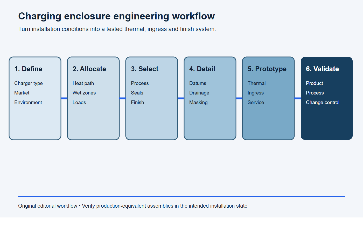
- Define: charger type, contained equipment, destination market, installation and service conditions.
- Allocate: heat paths, wet/dry zones, structural loads, electrical interfaces and appearance zones.
- Select: alloy, manufacturing route, joint architecture, gasket, vent and finish system.
- Detail: datums, tolerances, masking, drainage, hardware and inspection condition.
- Prototype: correlate thermal analysis and refine sealing, assembly and service behavior.
- Validate: test production-equivalent assemblies against the compliance and customer plan.
What should an enclosure RFQ include?
Paste this scope into the RFQ and attach the controlled drawing, CAD model, thermal inputs and compliance matrix.
RFQ scope: Please quote [charging-enclosure part number and revision] for [prototype quantity] and [annual volume]. The installation is [indoor/outdoor and mounted condition], the destination markets are [markets], heat dissipation is [watts and locations], and required enclosure targets are [IP/NEMA/impact/corrosion targets]. Quote the proposed aluminum alloy, manufacturing route, joints, finish, tooling, unit price, lead time and capacity. List every assumption and deviation.
Required evidence: Provide material traceability, dimensional and finish inspection, special-process records, thermal-test support, ingress-test configuration, coating and adhesion results, first-article documentation, packaging controls and change-notification triggers. Identify certification or complete-product testing outside the enclosure supplier’s scope.
- 3D model, controlled 2D drawing and revision level
- Charger architecture, annual volume and prototype schedule
- Alloy and temper, or permission for a documented supplier recommendation
- Manufacturing route constraints and acceptable joining methods
- Critical thermal interfaces, heat loads and flatness condition
- Ingress, impact, corrosion and product-standard targets with test configuration
- Gasket, vent, cable gland, hinge, latch and fastener specifications
- Finish system, color/gloss/texture window, appearance zones and approved samples
- Masking, rack/contact locations, bonding points and post-finish dimensions
- Inspection plan, documentation, packaging and change-control requirements
Stop conditions: the enclosure is not ready for release
Pause tooling or production release when any item below is unresolved.
- the destination market, product standard or installed test configuration is unknown;
- heat-loss values, ambient range, solar load or allowable component temperatures are missing;
- the ingress boundary is incomplete at doors, vents, glands, displays or service panels;
- gasket compression, latch force, flange flatness or drainage has no measurable acceptance rule;
- IP and NEMA designations are being treated as direct equivalents;
- dissimilar-metal contacts, grounding points or coating interruptions lack a corrosion plan;
- finish color, gloss, texture, appearance zones, masking or rack locations are undefined;
- validation uses an enclosure without production-equivalent hardware and interfaces.
Send functional requirements before freezing every dimension. BAOSONG can review the manufacturability of aluminum extrusions, castings, sheet-based assemblies and CNC-machined interfaces against the supplied drawing and verification plan. Use the contact page to request an engineering review.
Frequently asked questions
Is aluminum suitable for an outdoor EV charging enclosure?
Yes, when the alloy, structure, joints, drainage, dissimilar-metal interfaces and finish are designed for the environment. Outdoor suitability is established by the complete product design and its verification, not by aluminum alone.
Does a machined or cast aluminum box automatically meet IP65 or IP66?
No. The result depends on the assembled boundary, including doors, gaskets, latches, vents, glands, windows, connectors and test configuration. Test the representative assembly to the selected requirement.
Is powder coating always better than anodizing outdoors?
No. Both can support outdoor applications when the alloy, pretreatment, process and exposure specification are appropriate. Choose from corrosion, UV, color, texture, electrical contact, dimensional and repair requirements.
Should cooling fins be inside or outside the sealed enclosure?
External fins can reject heat without admitting ambient air, while internal fins mainly redistribute heat to internal air unless coupled to an external path. The correct architecture follows heat load, airflow, contamination, touch temperature and maintenance constraints.
Can IP and NEMA ratings be converted directly?
No. NEMA publishes a one-direction comparison from NEMA enclosure types to IEC IP classifications and states that it cannot be used to convert an IP classification into a NEMA type.
What data should be reviewed before tooling?
Freeze the compliance route, component heat losses, environmental extremes, installed interfaces, sealing concept, critical tolerance stack, finish system, annual volume and validation plan. These inputs can change the optimal split among extrusion, sheet, casting and machining.
Recommended Downloads for Aluminum Surface Finish Control
Use these BAOSONG references to select a finish, define cosmetic acceptance and prepare a production-ready requirement.
- Aluminum Surface Finish Selection Guide (PDF)
- Anodizing Guide: Color, Masking & Cosmetic Standards (PDF)
- Powder Coating, Brushing & Polishing Guide (PDF)
- Surface Finish Comparison Chart (editable Excel)
- Cosmetic Surface Requirement Template (editable Excel)
- Appearance Requirement Template (editable Excel)
Need help matching color, masking, gloss or cosmetic zones to your drawing? Contact BAOSONG engineering support.
