
Quick answer: what is multi-axis CNC machining and when do you need it?
Multi-axis CNC machining uses computer-controlled linear and rotary motion to change how a cutting tool approaches a workpiece. In milling, the term commonly describes a machine with more than the three linear X, Y and Z axes, such as a four-axis system with one rotary axis or a five-axis system with two rotary axes.
You need multi-axis machining when rotary positioning solves a real manufacturing problem: reaching features on several sides, drilling at compound angles, machining around a circumference, using shorter tools in deep regions, controlling relationships across faces, or continuously changing the tool direction along a complex surface.
You may not need it when the important features are accessible from fixed directions and a conventional three-axis process can hold the drawing requirements through simple, repeatable setups. The useful question is not “Is this part complex?” but “Which feature or relationship requires another controlled orientation?”
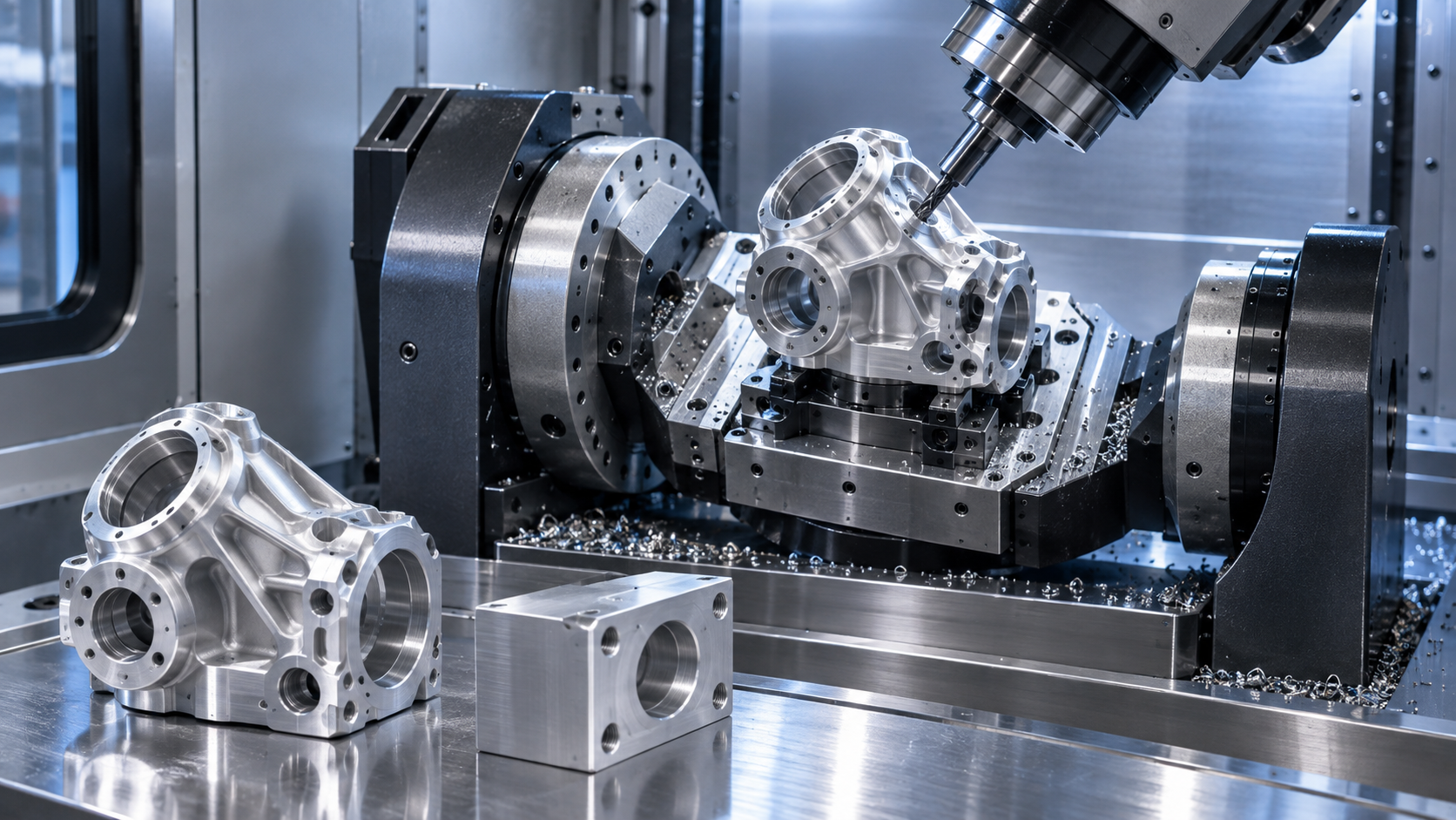
Seven-step multi-axis machining review
| Step | Decision | Required output |
|---|---|---|
| 1 | Map feature directions, datums and blocked approaches | Access and relationship map |
| 2 | Select indexed 4-axis, simultaneous 4-axis, 3+2, 5-axis or mill-turn candidate | Named machining mode |
| 3 | Separate positioning from simultaneous cutting | Toolpath ownership by feature |
| 4 | Prove why rotary motion is needed | Documented access or setup benefit |
| 5 | Compare a conventional 3-axis route | Minimum-capability baseline |
| 6 | Validate kinematics, workholding, tools and inspection | Machine-specific process plan |
| 7 | Compare complete cost and release production | Accepted-part quotation and control plan |
Step 1: map how rotary motion changes tool access
A three-axis milling machine positions the cutter relative to the work along three linear directions. Reaching another side normally requires a new setup, an angle fixture or another method of presenting that face to the spindle.
Adding rotary motion lets the machine orient the part or spindle under CNC control. Autodesk’s multi-axis machining overview describes four-axis milling as three linear axes plus one rotational axis and simultaneous five-axis as coordinated motion across all five axes. The physical rotations may come from the table, the spindle head or a mixed arrangement.
The extra orientation can expose a feature that a fixed tool direction cannot reach, improve holder clearance or keep several faces within one clamping. It does not remove every geometric limitation. The fixture, part, spindle, holder and tool still need a collision-free path inside the machine’s actual envelope.
Step 2: select the multi-axis mode
“Multi-axis” is a family of processes. The quotation should identify which mode creates each feature.
| Mode | How it moves | Useful feature pattern | Key review point |
|---|---|---|---|
| Indexed 4-axis | One rotary axis positions and locks before cutting | Multiple sides or repeated angular positions | Rotary centerline, support and indexing relationship |
| Simultaneous 4-axis | One rotary axis moves during the cut with linear axes | Wrapped paths and features around a cylinder | Rotary toolpath, surface behavior and cable or fixture clearance |
| 3+2 positional machining | Two rotary axes orient and lock; three linear axes cut | Angled planes, holes and multi-sided pockets | Fixed orientation, work offset and rotary accuracy |
| Simultaneous 5-axis | Three linear and two rotary axes interpolate during cutting | Blades, impellers and continuously changing tool directions | Tool-axis control, machine kinematics and collision simulation |
| Multi-task turning | Turning combines with live rotary tools, extra axes or a sub-spindle | Rotational bodies with flats, cross-holes, ports or milled features | Main/sub-spindle transfer, axis configuration and feature ownership |
Step 3: separate indexed and simultaneous motion
An axis can position the workpiece and stop, or it can move while the cutter is engaged. This difference changes programming, cutting conditions and risk.
In 3+2 machining, two rotary axes aim the workpiece or spindle at a fixed angle. They remain locked while a three-axis path cuts. Angled holes and side pockets often need orientation without continuous five-axis movement. Autodesk’s five-axis guide describes 3+2 as fixed tool orientation after positioning.
In simultaneous five-axis machining, the tool direction changes along the cutting path. This can follow a blade, impeller, curved wall or other surface where one fixed orientation cannot maintain access. HEIDENHAIN’s rotary-axis technical paper similarly distinguishes locked 3+2 positioning from synchronous interpolation of three linear and two rotary axes.
A five-axis machine can perform either mode. A part produced on that machine should not be described as simultaneous five-axis unless the toolpath actually uses coordinated rotary motion during cutting.
Step 4: prove that the part needs multi-axis machining
1. Critical features appear on several faces
A housing may have a mounting base, bores on adjacent faces and connector openings around the body. Rotary positioning can present these faces without repeatedly removing and locating the part. The benefit is strongest when their relationships are difficult to transfer through separate fixtures.
2. Holes or surfaces have compound angles
An angled feature that is not parallel to a primary machine plane may require a special fixture on a three-axis machine. Two rotary axes can orient it directly toward the spindle. Fixed-angle features usually suggest 3+2 positioning before simultaneous five-axis.
3. Geometry wraps around a cylindrical body
Radial holes, windows, helical paths and repeated features around a tube or sleeve can suit four-axis machining. One controlled centerline replaces several manually indexed positions, provided the part can be gripped and supported through rotation.
4. The holder blocks a fixed-angle approach
A cutter may nominally reach a deep pocket while the holder collides with a wall. Tilting the work or spindle can create clearance and allow a shorter, more rigid tool. The complete tool assembly and fixture must be checked, not only the cutter tip.
5. Tool direction must change along a curved surface
Blades, impellers and compound contours can require continuous orientation so the effective cutting region follows the surface. This is a genuine simultaneous multi-axis problem and needs suitable CAM, postprocessing and simulation.
6. Re-clamping would break a critical relationship
If a bore, face and hole pattern must relate through one datum reference frame, a rotary setup may keep them in one clamping. This can reduce a datum-transfer step, though the rotary transformation and machine calibration still influence the result.
7. Repeat production justifies setup consolidation
Reduced manual handling can improve throughput and process consistency for a suitable part family. The economic case depends on actual fixture, programming, cycle, inspection, batch and automation costs rather than a universal quantity threshold.
Step 5: compare a conventional 3-axis route
Many precise components do not need extra rotary axes. A plate with pockets and hole patterns, a top-open enclosure, a fixture block or a bracket with features accessible from fixed directions may be simpler to produce on a rigid three-axis machine.
Use three-axis with planned secondary setups when:
- the feature directions are orthogonal and easy to fixture;
- the functional datums can be transferred reliably;
- tools and holders reach each surface without excessive projection;
- the expected quantity does not justify complex rotary workholding;
- a simple process produces the accepted component at lower total risk or cost.
Extra axes can add programming, postprocessor, calibration, collision and verification work. They should solve a documented limitation. BAOSONG’s aluminum CNC milling page gives context for conventional prismatic components, while its multi-axis aluminum machining page covers the broader service route.
Multi-axis machining is not limited to five-axis milling
The term is often associated with five-axis machining centers, but production equipment combines motion in several ways. A four-axis mill uses one rotary axis. A turning center may add C-axis spindle control, live tools, a Y axis, a second spindle or additional turrets. A mill-turn platform can combine broader rotational and milling operations.
Autodesk’s machine-kinematics documentation distinguishes turning machines with live tooling from milling-based mill-turn systems. This matters because identical axis counts do not guarantee identical access, stock handling or process capability.
For a shaft with a keyway and radial hole, start from the rotational features and evaluate aluminum CNC turning with suitable secondary motion. For a multi-faced housing or curved bracket, start from milling access and fixture orientation. Let the controlling geometry choose the platform.
Step 6: validate precision, programming and workholding
Rotary positioning can help precision when it removes a manual relocation between features that must relate to one another. It can also introduce new error sources: rotary-axis positioning, pivot-point calibration, kinematic transformation, thermal behavior and the distance between the rotary center and the feature.
HEIDENHAIN notes that rotary-axis positioning errors translate directly to the workpiece during five-axis machining. Siemens’ SINUMERIK simultaneous-machining manual explains that tool orientation must be programmed together with tool-tip position and that the physical result depends on machine kinematics.
The drawing should distinguish size, form, orientation, location and runout requirements. ASME Y14.5-2018 (R2024) supplies the current listed North American language for stating and interpreting GD&T. The chosen project standard and datum structure control the acceptance requirement; “five-axis precision” is not a substitute.
Programming, simulation and postprocessing are part of the process
Multi-axis CAM must control the cutting point, tool orientation, lead and tilt, linking moves and avoidance of the part, fixture and machine. A correct cutter path can still fail if the postprocessor outputs motion that does not match the machine’s axis convention, limits or control functions.
A production-ready review should include:
- the actual machine kinematic model;
- stock, part, fixture, clamps, tool and holder;
- rotary travel, preferred orientation and unwind behavior;
- collision and near-collision checks through linking moves;
- safe tool changes, probing and retracts;
- verified postprocessor and control configuration;
- a controlled prove-out plan.
For simultaneous five-axis work, tool-axis changes can interact with feed, surface marks and machine motion. The programmed path should be evaluated on the intended machine rather than treated as a portable generic file.
Workholding and usable envelope can decide feasibility
A rotary table or trunnion consumes space, and the workpiece sweeps through a larger volume as it tilts. A part that fits at zero degrees may collide with the spindle, holder, enclosure, cables or fixture at another orientation.
Workholding must expose the needed faces while resisting cutting forces. Tall risers can improve access but change stiffness and sweep. Cylindrical parts may need tailstock support. Thin aluminum housings may require shaped nests or controlled clamp load to avoid machining and inspecting them in a distorted state.
Ask the supplier for the proposed orientation, grip surfaces, remaining inaccessible area and second-operation plan. One-setup machining is useful only when the chosen workholding supports the component and the required features.
Step 7: evaluate complete cost and production value
Multi-axis machining may reduce fixtures, handling and queues, allow shorter tools or consolidate inspection stages. It may also require more expensive equipment, programming, simulation, rotary workholding and calibration. Neither effect can be converted into a universal price multiplier.
Compare the same accepted component through two or more complete routes:
- number of setups and manual transfers;
- fixture and soft-jaw cost;
- programming, simulation and prove-out;
- roughing, finishing and deburring cycle;
- tool reach, expected wear and access risk;
- first-article and recurring inspection;
- batch size, loading method and design-change exposure.
A higher machine rate can still support a lower total cost when it removes difficult operations. A simpler route can remain better when rotary motion adds no useful access or relationship control. Request a finished CNC machining quotation rather than comparing nominal machine-hour rates.
A requirement-to-process decision table
| Requirement | Candidate route | Limiting condition | Verification method |
|---|---|---|---|
| Features on two accessible orthogonal sides | 3-axis with two controlled setups | Datum transfer and fixture repeatability | Feature inspection in the drawing datum frame |
| Repeated radial ports around a sleeve | Indexed 4-axis | Centerline, support and angular access | Port position and angular relationship |
| Several fixed compound-angle bores | 3+2 positional machining | Rotary envelope and tool/holder clearance | Bore position and orientation to datums |
| Blade with changing normal direction | Simultaneous 5-axis | Tool-axis control, collision and machine kinematics | Surface profile and controlled process prove-out |
| Turned body with flats and cross-holes | Live-tool turning or turn-then-mill | Axis availability and feature relationships | Rotational and off-axis features in specified setups |
Three hypothetical examples
These examples illustrate process selection and are not BAOSONG customer cases.
Robotic joint housing with angled bearing bores
Requirement: several faces and bores must relate to the mounting datum. Candidate: 3+2 positional machining to orient each fixed bore. Limit: trunnion clearance, workholding stiffness and rotary calibration. Verify: bore position, orientation and bearing-interface size in the drawing datum frame.
Aluminum sleeve with equally spaced windows
Requirement: windows and holes repeat around one centerline. Candidate: indexed or simultaneous four-axis machining. Limit: grip length, wall distortion, angular indexing and burr access. Verify: centerline relationship, angular pattern and edge condition.
Impeller with curved blades
Requirement: the cutter must follow surfaces with continuously changing orientation. Candidate: simultaneous five-axis machining. Limit: holder access, collision, postprocessor, remaining stock and surface strategy. Verify: surface profile, visual toolpath consistency and documented inspection coverage.
Production release checklist
- Identify the feature and relationship that requires each rotary motion.
- Name indexed, 3+2 or simultaneous cutting for each affected feature.
- Confirm the actual head/table kinematics, rotary limits, pivot calibration and usable envelope.
- Simulate stock, part, fixture, clamps, holder and the complete rotary sweep.
- Define machining and inspection datums, including any second-side operation.
- Approve the first article for dimensions, finish, burrs and functional assembly.
- Require review when the machine, postprocessor, fixture, sequence or stock changes.
Stop conditions: multi-axis machining is not ready
- “Complex part” is the only reason given for using additional axes.
- The quotation says five-axis without distinguishing 3+2 from simultaneous motion.
- A simpler 3-axis or 4-axis route has not been evaluated.
- The CAM simulation omits the real machine, fixture, holder or stock.
- Critical relationships cross operations without a datum-transfer plan.
- Rotary-axis calibration, tool-center-point control or inspection method is undefined.
- Cost comparison excludes programming, postprocessing, fixtures, inspection and accepted-part yield.
Copy-ready multi-axis machining RFQ checklist
- matching-revision 3D model and 2D drawing;
- functional datums, critical relationships and mating components;
- alloy, temper, stock form and approved substitutions;
- angled features, inaccessible regions and required surface continuity;
- features that should remain in one clamping;
- surface texture, edge, coating, masking and cosmetic requirements;
- prototype, launch and repeat quantities with variant mix;
- inspection, traceability and report requirements.
BAOSONG’s engineering support, quality overview and surface-finishing resources identify useful project inputs. Applications such as robotics and automation components still require drawing-specific review; an industry label alone does not establish the axis strategy. Send the drawings and demand stages for a manufacturing-route discussion.
Frequently asked questions
Does multi-axis always mean simultaneous five-axis?
No. It can include indexed four-axis, simultaneous four-axis, 3+2 positional machining, simultaneous five-axis and multi-task turning configurations. The process plan should identify which axes move during each cut.
Can multi-axis machining improve tolerance control?
It can help when rotary positioning keeps related features in one clamping. Rotary calibration, kinematics, workholding, temperature and measurement still affect the result, so no axis count guarantees a tolerance.
Do parts with five machined sides require five-axis machining?
No. Several fixed-direction setups on a three-axis machine may be suitable. Five-axis becomes valuable when two rotary orientations improve access, datum control, tooling or total production efficiency.
Is 3+2 less capable than simultaneous five-axis?
It solves a different problem. 3+2 is well suited to fixed-angle planes, holes and pockets. Simultaneous motion is needed when tool orientation must change continuously along the cut.
What is the clearest sign that a part needs multi-axis machining?
A critical feature cannot be reached, related or machined with a practical fixed-direction setup and tool assembly. Confirm that rotary motion solves that specific issue before selecting the more complex route.
Recommended Downloads for CNC Machining Design
Use these BAOSONG references to improve tool access, feature geometry, practical tolerances and CNC process planning before release.
- Aluminum CNC Machining Design Guide (PDF)
- CNC Milling Guide: Pockets, Walls, Corners & Tool Access (PDF)
- CNC Turning Guide: Diameters, Threads & Concentric Features (PDF)
- CNC Machining Tolerance Guide (reference sheet)
- Aluminum Part Design Checklist (editable Excel)
Need help reviewing a machined part or feature stack? Contact BAOSONG Precision.
