
Quick answer: which features and tolerances are critical on a CNC-machined aluminum motor housing?
The most critical features are usually the bearing seats, stator-locating bore or register, end-shield pilots, shaft-seal bores, mounting datums, sealing faces and the geometric relationship among their axes and faces. Their limits should come from bearing fit, rotor air gap, stator retention, thermal expansion, sealing, vibration and assembly requirements rather than a generic “precision machining” tolerance.
Use a functional datum system and control size, form, orientation, location and runout separately where each affects performance. A bearing bore can meet its diameter limit yet be out of round; two bores can each be acceptable yet misaligned; a flange can be flat yet not square to the shaft axis. The drawing and inspection plan must distinguish these conditions.
Machine related bores and faces in as few datum transfers as practical, then verify them in the condition that represents assembly and operation. Account for aluminum’s temperature response, thin-wall distortion, casting or extrusion stock variation, coating, fastener preload and measurement uncertainty before releasing tolerances for production.
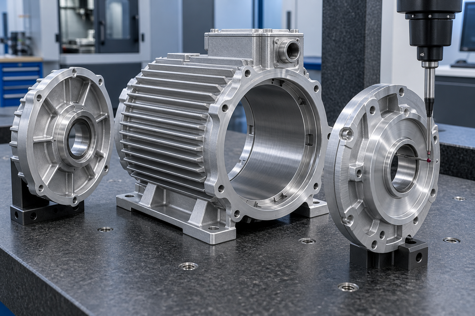
Begin with the motor architecture and operating state
Use this order before assigning bore tolerances:
- Define operating conditions. Record bearing arrangement, speed, loads, duty cycle, temperature map, cooling, sealing and mounting.
- Map the functional chain. Connect the rotor axis, bearing seats, stator register, end-shield pilots, seal bores and machine mounts.
- Build the datum system. Choose references that reproduce assembly function and allocate the permissible assembled error among components.
- Separate each control. Specify size, form, orientation, location, runout and surface texture only where each has a functional reason.
- Plan production and verification together. Define stock, setups, coating state, restraint, temperature and measurement method before release.
A motor housing can support the stator, locate two end shields, retain bearings, transmit torque to a machine frame, reject heat, protect internal components and carry seals, connectors and cooling features. Some designs use the central housing as the stator reference; others locate bearing carriers through end-shield pilots or separate cartridges.
Record the motor type, speed range, duty cycle, torque reaction, rotor mass and imbalance, bearing arrangement, cooling method, temperatures, environment, sealing level, mounting orientation, expected life and service strategy. Identify the locating and non-locating bearing positions and how thermal shaft growth is accommodated.
For vibration requirements, IEC 60034-14:2018 defines factory-acceptance vibration procedures and limits for certain uncoupled electrical machines within its stated shaft-height, power and speed scope. It does not apply automatically to every traction motor, servo, spindle or integrated drive. Use the machine’s actual governing specification.
Build a critical-feature matrix
| Feature | Functional risk | Drawing controls to consider | Verification |
|---|---|---|---|
| Bearing housing bore | Ring creep, excessive interference, loss of clearance, noise or shortened life | Final-state size, cylindricity or roundness, texture and shoulder geometry | Air/electronic gauging, bore measurement and form measurement as required |
| Two-bearing axis relationship | Shaft bending, bearing load, friction and vibration | Position, runout or another function-based coaxial relationship to datums | CMM, mandrel, spindle or specialized alignment method |
| Stator register or bore | Air-gap variation, poor heat transfer, stator movement or difficult assembly | Size, form, position, texture and retention method | Bore/form data and representative assembly test |
| End-shield pilot and flange | Bearing-axis shift and end-face misalignment after assembly | Pilot fit, face flatness, perpendicularity or runout, bolt-pattern position | Component inspection plus assembled relationship check |
| Shaft-seal bore and face | Leakage, wear or seal damage | Size, axis relationship, surface texture, lead and edge condition | Dimensional, texture and functional leak/run test |
| Mounting feet or flange | Motor misalignment, soft foot, housing distortion and vibration | Flatness, coplanarity, position and relationship to motor axis | Surface plate/CMM plus installed alignment |
| Cooling jacket or fin base | Hot spots, coolant leakage or thermal distortion | Wall, flatness, channel boundary, ports and pressure requirements | Dimensional, leak/pressure and thermal tests |
The matrix should connect each controlled characteristic to a failure mode and measurement method. This makes it easier to identify tolerances that protect real function and remove tight limits that do not change assembly or performance.
Create datums from assembly function
A useful datum reference frame constrains the housing as it is located in the motor or machine. A common concept may begin with a primary mounting plane, a secondary pilot or bore axis and a tertiary clocking feature, but the correct order depends on the design. Do not select the largest convenient machining surface if it does not control assembly.
Show how the central housing and end shields transfer the datum. If bearing bores sit in separate covers, pilot diameters, joint faces, dowels and fastener patterns all influence the assembled axis. Component tolerances should be allocated from the allowable assembled error.
ASME Y14.5-2018 (R2024) establishes the GD&T language used to state and interpret geometric requirements. ISO 1101:2017 provides the ISO symbol language for tolerances of form, orientation, location and runout. Use the drawing’s selected system consistently rather than mixing defaults from both.
Specify bearing seats from the bearing system
A bearing housing fit depends on bearing type and tolerance class, ring load, load direction, speed, duty, internal clearance, housing material and stiffness, temperature difference, assembly method and whether the ring must move axially. The bearing manufacturer’s application guidance should drive the fit selection.
SKF’s guide to rolling bearings in electric motors and generators specifically discusses aluminum-housing fits and temperature differences. Aluminum expands differently from bearing steel, so a fit chosen at inspection temperature may change during operation. The guide also distinguishes arrangements that need axial displacement.
Do not copy H7, K7 or another tolerance class into every motor drawing. ISO 286-1:2010 defines the ISO system for linear-size tolerances and fits; it does not choose the functional fit for a motor designer. State the nominal size, tolerance class or limits, final material/coating condition and reference temperature required by the project.
Control bore size, form and surface separately
Bore diameter alone does not show lobing, taper, barrel shape, bell-mouth or local damage. An interference fit on an out-of-round seat can distort the bearing ring. A thin housing can also change shape when unclamped, after end-shield bolts are tightened or as temperature rises.
Specify the form characteristic needed by the bearing analysis and the evaluation method. For production, an air gauge may provide fast comparative size and form information; a bore gauge provides selected diameters; a roundness instrument or CMM may address other aspects. No single method automatically proves every requirement.
Define the axial measurement zone and exclude chamfers or reliefs deliberately. Control the bearing shoulder’s contact face, corner radius, undercut and edge condition so the ring seats fully without damage.
Align bearing bores through the assembled stack
Two bearing bores may be machined in one housing, split between a body and end shield, or contained in two covers. The tolerance scheme should control the shaft-supporting relationship after pilots, fasteners, dowels, gaskets and joint faces are assembled.
Coaxiality is a functional idea; the drawing may express it through position, runout or another geometric control selected for the actual degrees of freedom and inspection method. Avoid a generic note saying “bores must be concentric” without a datum, tolerance zone and verification plan.
When possible, finish related bores in one setup or through a controlled line-boring process. If the geometry requires multiple setups, create repeatable datums and prove the transfer. For covers, consider inspecting the assembled housing with a master mandrel, CMM strategy or functional spindle method where that better represents shaft alignment.
Control the stator seat for air gap, retention and heat flow
The stator interface may use an interference fit, thermal assembly, adhesive, keys, pins, clamps or another retention method. Define what locates the stator axis, what resists torque and how the heat path reaches the housing. These functions may occur on different surfaces.
Size and form affect assembly force and air-gap consistency. Surface texture and cleanliness affect adhesive bonding or thermal contact. Slots, wire exits and local wall changes can reduce stiffness and influence bore distortion. Model and measure the housing in the relevant condition.
If the stator is installed by heating the aluminum housing, validate the assembly temperature, coating, handling and residual fit. The production plan should prevent permanent distortion or surface damage and should define whether the stator bore is measured before assembly only or verified indirectly after assembly.
Relate end-shield pilots and faces to the motor axis
The pilot locates the cover radially; the flange face locates it axially and controls tilt. Bolt clearance alone should not determine precision location when bearing alignment depends on the cover. Use dowels or other locating features only when their tolerance stack and assembly sequence are defined.
Control flange-face flatness and its orientation to the functional axis. Face runout can combine form and orientation effects in a way that may suit a rotating interface; perpendicularity may better express another design. Choose the control based on function and how it will be measured.
Fastener preload can pull a flexible cover or housing into a different shape. Inspect critical assembled relationships at the specified torque and sequence when the free-state component result does not predict operation.
Protect seals, ports and connector interfaces
Shaft seals need bore size, axis alignment, surface texture, edge lead-in and contact-face control. Avoid spiral machining lead where it can pump fluid along a seal path. State whether polishing, grinding or another final operation is required instead of assuming a turned or bored surface is acceptable.
Static gasket and O-ring grooves require controlled depth, width, surface condition, corner radii and mating-face flatness. Ports need thread, spotface, orientation and sealing requirements. Connector bosses may also carry cable loads that distort thin walls.
Define the leak-test boundary, medium, pressure, temperature, duration and acceptance rule for liquid-cooled or sealed housings. A dimensional inspection of the groove does not prove the assembled seal.
Design thin walls and cooling fins for machining stability
Aluminum housings often use thin cylindrical walls, ribs and fins to reduce mass and increase heat-transfer area. These features can vibrate during cutting, move under clamping and relax after material removal. Deep internal bores also amplify tool deflection and heat.
Keep wall transitions gradual, add local support near bearing carriers and mounting feet, and avoid fins that block tool or probe access. Plan sacrificial stock or intermediate stress-relief steps when the stock form and material removal make movement likely.
Use fixtures that support the part without forcing it round. A part can pass while clamped and distort after release. Inspection should state free-state or restrained condition and any allowed stabilization time.
Choose the near-net stock before detailing the process
Motor housings may start from billet, tube, extrusion, permanent-mold or die casting, sand casting or fabricated construction. Billet and tube reduce tooling for prototypes but may waste material. Extrusion suits constant cross-sections. Castings integrate fins, feet, ribs and connector bosses for repeated production but bring draft, porosity, stock and datum considerations.
Reserve machining allowance on critical bores, pilots, flanges and mounting surfaces. Avoid excessive stock that increases distortion and cycle time. Establish casting or extrusion datums that survive into CNC operations and allow consistent setup.
Compare aluminum die casting, aluminum extrusion and CNC machining from the expected quantity, geometry, material properties, tooling and verification needs.
Plan a machining sequence that preserves relationships
Create stable roughing datums, remove bulk stock, allow the part to relax where needed, then finish the related functional features. Leave enough material for final boring and facing after any process likely to move the housing.
Machine bearing seats, stator register, pilot and flange face in one orientation when access permits. Multi-axis equipment can reduce transfers, but machine-axis count does not guarantee accuracy; tool reach, spindle condition, thermal state, workholding and probing strategy still matter.
For long bores, choose boring tools and support that control straightness and taper. Verify tool wear and temperature. Use in-process probing to detect setup drift, while retaining independent final inspection for released characteristics.
Multi-axis aluminum machining can combine features around a housing, subject to part size, access, fixture and inspection review.
Account for coating and finishing in final dimensions
Anodizing, conversion coating, paint and other treatments can change dimensions, surface texture, electrical contact and fit. Identify bearing seats, stator interfaces, grounding areas, gasket lands and threaded features that require coating, masking or post-finish machining.
State whether limits apply before or after finishing. Mask transitions and rack-contact points need permitted locations. Aggressive mechanical preparation can round edges or change sealing surfaces, while residues can affect adhesive or thermal interfaces.
Coordinate aluminum surface finishing and anodized aluminum requirements with bearing and seal fits before releasing the drawing.
Control surface texture by function
Bearing seats, seal bores, gasket lands, adhesive surfaces and thermal interfaces need different textures. A single general Ra note can overcontrol hidden surfaces while failing to define direction, waviness or isolated defects where they matter.
ASME B46.1-2019 (R2026) defines surface texture and its roughness, waviness and lay constituents. State the parameter, limit, evaluation method, cutoff or filter where needed, and machining-lay requirement. Keep cosmetic defect limits separate from texture measurements.
Measure on accessible representative locations and relate the result to performance. A stylus path across a curved or interrupted surface may need a special method or a qualified process proxy.
Calculate tolerance stacks at operating temperature
Room-temperature dimensions support manufacturing control, but the motor operates with gradients among housing, stator, bearings, shaft and coolant or air. Aluminum’s thermal response differs from bearing steel and other inserts. Evaluate bearing fit, rotor air gap, seal position and axial freedom across the defined temperature range.
Include material properties, component dimensions, heat sources, cooling, contact conductance and assembly preload. Validate the model with temperature and dimensional or performance data from representative hardware. Do not apply one uniform temperature to a system with known gradients.
Use worst-case or statistical stacks according to project policy and input evidence. Keep manufacturing tolerance, assembly variation, thermal movement and measurement uncertainty visible rather than hiding them inside one unexplained limit.
Match each tolerance to a capable measurement
| Characteristic | Possible method | Critical setup condition | What it may not prove alone |
|---|---|---|---|
| Bearing-bore size | Air gauge, bore gauge, CMM or calibrated master | Temperature, axial locations and free/restrained state | Full cylindricity or assembled axis |
| Roundness or cylindricity | Form instrument or qualified CMM strategy | Support, filtering, point density and evaluation rule | Operational deformation after assembly |
| Axis relationship | CMM, precision mandrel, spindle or specialized fixture | Datum realization and assembled/free state | Bearing performance under thermal load |
| Flange flatness/orientation | CMM, surface plate, indicator or optical method | Support points, torque and temperature | Sealing under actual gasket compression |
| Surface texture | Stylus, optical method or process correlation | Parameter, cutoff, direction and accessible location | Isolated scratches or appearance |
| Cooling or sealing function | Leak, pressure, flow and thermal test | Medium, pressure, temperature, duration and boundary | Unrelated dimensional characteristics |
NIST’s work on uncertainty and dimensional calibrations emphasizes that every measurement is an estimate with uncertainty. Use calibrated equipment, appropriate resolution and an uncertainty suitable for the acceptance decision. Guardbanding and measurement-system analysis should follow the customer’s quality plan.
Verify the housing at component and motor levels
Component inspection establishes material, dimensions and geometric relationships. Assembly tests reveal bearing preload or clearance, rotor freedom, air-gap effects, seal performance and distortion under torque. Motor tests address vibration, noise, temperature, efficiency and durability within the applicable design.
When a performance failure occurs, preserve the link to housing characteristics rather than tightening every tolerance. Correlate bore form, axis alignment, mounting condition, balance, bearings, rotor, stator and thermal state. Correct the feature that drives the failure mode.
Connect results to controlled quality and inspection records. Define first-article, in-process and final evidence before production so critical characteristics do not depend on a one-time laboratory check.
A practical motor-housing tolerance workflow
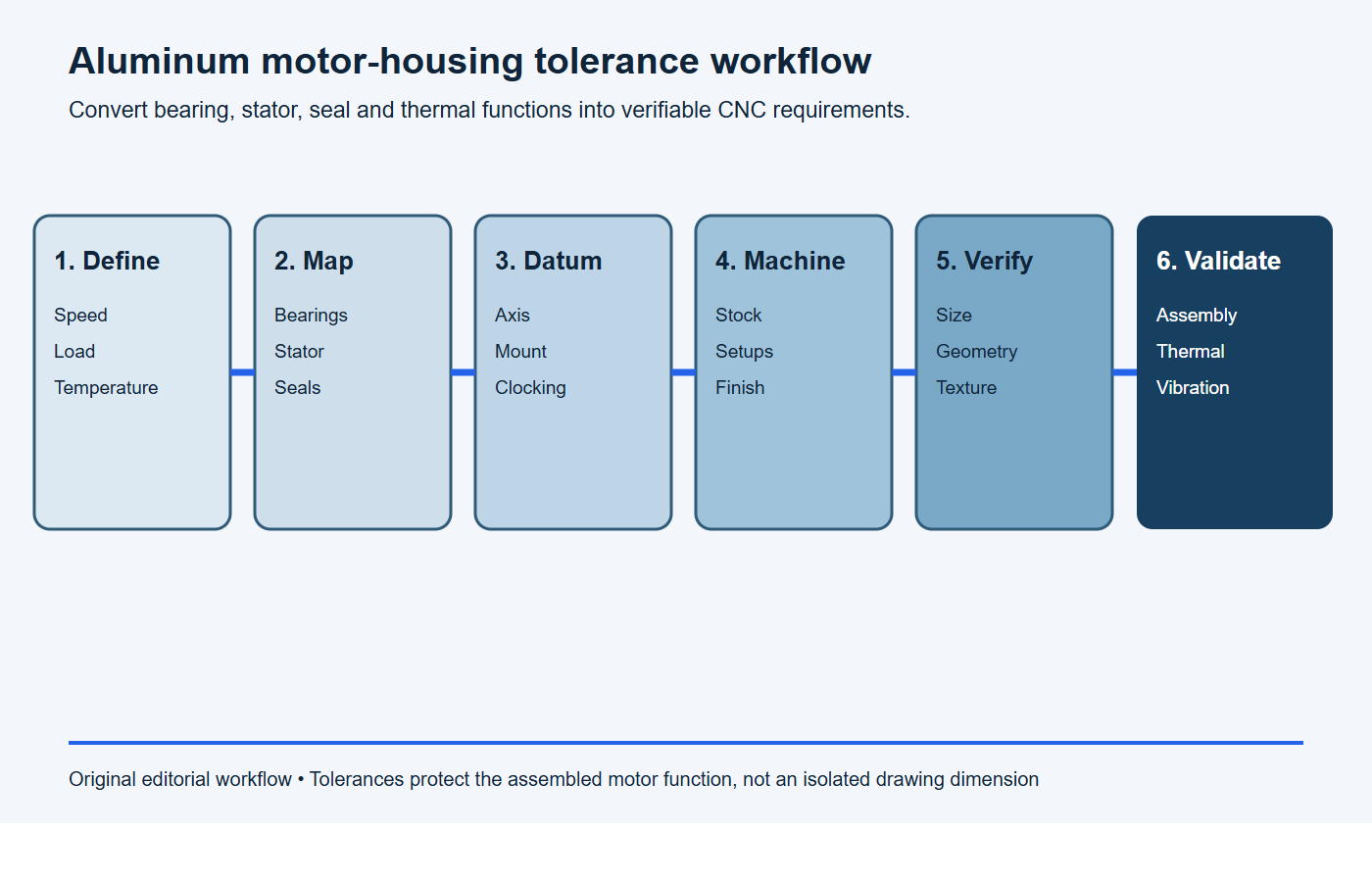
- Define operation. Record motor architecture, loads, speed, temperatures, cooling, sealing and bearing arrangement.
- Map interfaces. Identify bearing, stator, end-shield, seal, mount, connector and cooling functions.
- Create datums. Constrain the housing from assembly function and allocate the assembled error budget.
- Plan machining. Select stock, setups, sequence, stress control, finishing and protected surfaces.
- Plan measurement. Match size, form, location, orientation, runout and texture to capable methods.
- Validate and control. Correlate component results to assembled performance and preserve production evidence.
RFQ checklist for CNC-machined aluminum motor housings
Paste this scope into the RFQ and attach the controlled drawing, CAD model, bearing data and assembled tolerance stack.
RFQ scope: Please quote [motor-housing part number and revision] for [prototype quantity] and [annual volume]. The housing supports [bearing arrangement], locates [stator or end shields], operates at [speed, load and temperature range], and uses [cooling and sealing concept]. Quote the proposed stock form, aluminum alloy and temper, machining setup, special processes, tooling, unit price, lead time and capacity. Identify every requested drawing deviation.
Required evidence: Provide material traceability, first-article results, bore size and form data, datum-related runout or position results, surface-texture evidence, final-finish inspection, leak or pressure results where applicable, measurement uncertainty for critical characteristics and change-control triggers.
- 2D drawing, 3D model and selected GD&T standard;
- motor type, speed, duty, torque reaction and mounting orientation;
- bearing part numbers, arrangement, loads, clearance and fit analysis;
- stator location, retention, thermal interface and air-gap budget;
- functional datum reference frame and assembled stack;
- critical sizes, form, orientation, location, runout and textures;
- free-state, restrained and final-assembly inspection conditions;
- operating temperature map and thermal-growth analysis;
- stock form, alloy, temper, casting/extrusion requirements and machining allowance;
- coating, masking, grounding, sealing and post-finish dimensions;
- cooling-jacket boundary, ports, leak and pressure requirements;
- first-article, production sampling, records and change control.
Stop conditions: the motor housing is not ready for release
Pause production release if any point below is unresolved. These gaps can produce a housing that passes individual dimensions but fails after bearings, stator and end shields are assembled.
- bearing part numbers, fits, loads, internal clearance or operating temperatures are unknown;
- the drawing does not connect bearing, stator, seal and mounting features through a functional datum system;
- bore diameter is specified without the required form, axis relationship or surface condition;
- the assembled coaxiality or runout budget has not been allocated across housing and end shields;
- inspection condition, restraint, reference temperature or coating state is undefined;
- thin walls, fins or interrupted cuts cannot be machined and released without unacceptable distortion;
- the proposed gauge or CMM method cannot demonstrate the required uncertainty;
- component inspection has no defined link to assembled vibration, air gap, sealing or thermal validation.
Frequently asked questions
What is the most important tolerance on a motor housing?
There is no single universal tolerance. Bearing-seat fit and the relationship between bearing axes, stator register, end-shield pilots and mounting datums often dominate, but the correct priority comes from the motor’s failure modes and assembly stack.
Is H7 always suitable for an aluminum bearing housing?
No. A fit class must match bearing type, load, ring condition, clearance, speed, housing stiffness, assembly and temperature. Aluminum’s thermal behavior can change the operating fit, so use bearing-manufacturer and motor-design analysis.
Should both bearing bores be machined in one setup?
It is often beneficial when access allows because it reduces datum transfer, but one setup does not guarantee conformance. Tool reach, deflection, thermal state, workholding and final measurement still need control.
Can a CMM verify motor-housing coaxiality?
A qualified CMM strategy can verify defined geometric requirements if datum realization, sampling, fitting algorithm and uncertainty are suitable. It may not reproduce deformation under bearing fits, bolts or operating temperature, so assembly validation can still be necessary.
Should motor-housing dimensions apply before or after anodizing?
The drawing should state the required condition for every critical feature. Bearing seats, grounding points, seal lands and threads may be masked or finish-machined, while other surfaces receive the specified coating.
How can thin-wall distortion be reduced?
Use balanced geometry, stable near-net stock, controlled machining allowance, supportive low-force fixturing, staged roughing and finishing, practical tool access and inspection after release from the fixture.
Request an aluminum motor-housing manufacturing review
BAOSONG can review motor-housing stock, CNC access, datum strategy, bearing and stator interfaces, sealing surfaces, finish requirements and inspection inputs within the supplied drawing scope. Send the 2D drawing, 3D model, quantities and critical-feature requirements through contact us for a project-specific review.
Recommended Downloads for CNC Machining Design
Use these BAOSONG references to improve tool access, feature geometry, practical tolerances and CNC process planning before release.
- Aluminum CNC Machining Design Guide (PDF)
- CNC Milling Guide: Pockets, Walls, Corners & Tool Access (PDF)
- CNC Turning Guide: Diameters, Threads & Concentric Features (PDF)
- CNC Machining Tolerance Guide (reference sheet)
- Aluminum Part Design Checklist (editable Excel)
Need help reviewing a machined part or feature stack? Contact BAOSONG Precision.
