
Quick answer: what matters most in an aluminum robot joint housing?
The housing must locate the bearing system, reducer, motor, output flange, encoder and seals as one load-carrying assembly. The most important requirements are rarely a blanket machining tolerance. They are the size, form, orientation and runout relationships that preserve bearing fit, reducer alignment, output-axis accuracy, gear mesh or flexspline behavior, structural stiffness and sensor reference after assembly.
Build a functional datum system around the joint axis and its mounting interfaces. Control coaxial bores, shoulders and flange faces in the same datum frame; account for fastener preload, thin-wall distortion, coatings and operating temperature; and machine related features with as few datum transfers as practical. Verify the housing in the condition that represents the finished joint.
Aluminum helps reduce mass and spread motor and drive heat, but thermal gradients can change fits, preload and axis relationships. Define heat sources, duty cycle, cooling path, external loads and allowable temperatures before fixing alloy, wall thickness, tolerances or surface finish. Validate the complete actuator because a compliant housing, bearing, reducer or joint interface can each affect system behavior.
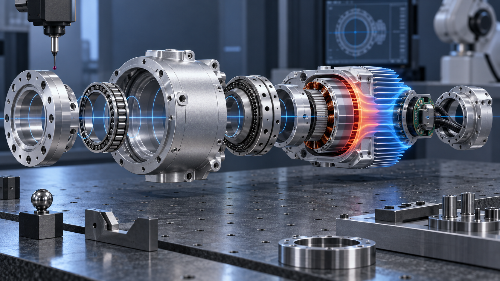
Begin with the actuator architecture and load path
Use this sequence before assigning a general machining tolerance:
- Define the actuator. Record bearings, reducer, motor, encoder, brakes, seals, links, loads, speed, duty cycle and temperature range.
- Trace the functional axis. Map how bores, shoulders, pilots and faces locate every rotating and stationary component.
- Allocate the error budget. Divide allowable runout, alignment, lost motion and interface error among the housing, covers, bearings, reducer and assembly.
- Plan machining and inspection together. Select stock, setups, datum transfers, coating state, restraint and measurement methods.
- Validate the assembled joint. Correlate housing results with joint stiffness, temperature, vibration, torque response and robot-level performance.
A robot joint may combine a frameless motor, strain-wave, cycloidal or planetary reducer, one or more bearings, an output flange, encoder, brake, torque sensor, seals and cable routing. Some designs integrate these elements into one cylindrical housing; others use a main shell, bearing carrier, motor sleeve and separate covers.
Map radial load, axial load, overturning moment, torque reaction, impact and emergency-stop load from the output to the arm structure. Record rotation range and speed, payload, reduction ratio, duty cycle, expected life, mounting orientation and service strategy. Identify which component establishes the rotation axis and which interfaces transmit load.
The housing should not be designed from payload alone. A short joint carrying a large moment can demand more stiffness than a higher-payload joint with a favorable load path. Dynamic acceleration, reducer stiffness, bearing arrangement and arm geometry all influence the requirement.
Create a critical-feature matrix before assigning tolerances
| Feature | Function | Possible drawing controls | Verification |
|---|---|---|---|
| Main bearing seat | Locates the output axis and supports joint loads | Final-state size, roundness/cylindricity, texture and shoulder geometry | Bore/form measurement and representative bearing assembly |
| Reducer locating pilot | Centers the reducer relative to bearing and motor axes | Size, position or runout, face orientation and bolt-pattern position | CMM or functional master in the housing datum frame |
| Motor stator seat | Locates the electromagnetic air gap and conducts heat | Size, form, axis relationship, texture and retention features | Bore/form data plus assembly and thermal verification |
| Output flange or bearing carrier | Transfers torque and moment to the next link | Pilot fit, face runout/perpendicularity, flatness and hole position | Datum-based CMM and assembled runout measurement |
| Encoder seat | Maintains sensor gap and angular reference | Axis position, face orientation, axial location and local flatness | Dimensional inspection and calibrated encoder installation |
| Torque-sensor interface | Transfers load without unintended stress or slip | Flatness, pilot/bolt position, texture and preload condition | Interface inspection and calibrated assembled response |
| Joint mounting face | Connects the actuator to the robot link | Flatness, pilot, hole pattern and relationship to rotation axis | CMM plus representative joint-stack measurement |
Link each characteristic to a failure mode and an inspection method. This exposes requirements that protect function and makes it easier to relax dimensions that do not affect the assembled actuator.
Define datums from assembly function
A common concept uses the primary mounting or reducer face to constrain axial location, a functional pilot or bearing axis to establish radial location, and a clocking hole or key to fix rotation. The correct order depends on how the joint is assembled and loaded. Do not select a broad convenient surface if it does not locate the working mechanism.
Show how datums transfer across covers, bearing carriers and the output member. If two bearing seats are in different components, pilot fits, faces, dowels, bolts and gasket layers all contribute to the assembled axis. Allocate the allowable joint error across this stack.
ASME Y14.5-2018 (R2024) establishes the North American drawing language for GD&T. ISO 1101:2017 provides the ISO geometrical-tolerancing symbol language. Select the governing system on the drawing and use it consistently.
Specify coaxiality as a controlled relationship
“Coaxial” describes the functional need for two or more rotational features to share an axis. The drawing must express how that relationship is established, what datum applies, the shape and size of the tolerance zone, the material condition if relevant and how acceptance will be measured.
Concentricity, position, circular or total runout and cylindricity are not interchangeable. A bore can meet diameter limits while being tapered or lobed. Two bores can each be round yet have offset or tilted axes. A flange face can be flat yet not square to the bearing axis. Control size, form, location/orientation and rotating-surface behavior separately where function requires it.
Avoid placing the same tight number on every bore. Derive limits from bearing clearance and preload, reducer manufacturer requirements, encoder gap, seal behavior, torque transmission and the allowable output error. State whether the requirement applies to a free housing, clamped housing or assembled joint.
Design bearing seats as part of the bearing system
Bearing-seat selection depends on bearing type, tolerance class, load direction, rotating load, preload, joint stiffness, housing material, wall thickness, temperature, installation method and serviceability. Cross-roller, angular-contact, deep-groove and thin-section bearings do not impose the same interface needs.
Choose the fit with the bearing supplier and actuator designer. Define seat diameter, form, shoulder contact, corner relief, retaining features and surface texture. A sharp corner can interfere with the bearing chamfer; a rough or damaged shoulder can tilt a ring; excessive interference can change internal clearance and deform a thin outer ring.
Aluminum and bearing steel respond differently to temperature. Evaluate fit and preload through the specified operating range, including local gradients. A room-temperature inspection result does not prove the operational bearing condition.
Keep reducer interfaces aligned with the output axis
A strain-wave reducer may require precise relationships among circular spline, flexspline or wave-generator interfaces. A cycloidal reducer may locate pins, discs, eccentric bearings and output elements through a different stack. Planetary systems add carrier and gear-center relationships. Use the selected reducer manufacturer’s controlled interface drawing rather than a generic robot-joint tolerance table.
Control the locating pilot, mounting face, bolt circle and dowel or clocking feature in the joint datum frame. Consider how fastener preload changes face contact and housing shape. If the reducer is cartridge-mounted, define the insertion lead, clearance, retention and removal path.
Measure the housing features and then verify the installed reducer/output behavior where the mechanism can introduce additional runout, lost motion or stiffness variation. Housing coaxiality is one contributor, not a complete joint-performance metric.
Locate the motor and encoder without overconstraining assembly
A frameless motor stator may be bonded, clamped, shrink-fitted or retained by a sleeve. The rotor may reference the reducer input or a separate shaft. Define which diameter establishes the air gap, how torque reaction is carried and how heat crosses the stator-to-housing interface.
Encoder performance depends on radial gap, axial gap, tilt, runout, magnetic or optical target condition and calibration. Place its locating features in a datum chain tied to the working axis, while allowing practical assembly access and adjustment where the sensor system requires it.
Keep motor leads, encoder cables and brake wiring away from pinch points and rotating interfaces. Cable passages, connector bosses and strain-relief loads can weaken or distort thin housing sections; include them in structural and thermal analysis.
Use ISO robot-interface standards within their actual scope
ISO 9409-1:2004, confirmed in 2023, defines main dimensions, designation and marking for circular plate mechanical interfaces intended for end-effector exchangeability and orientation. It does not define an internal reducer, bearing or motor interface, and it does not assign load capacity to a selected plate. NIST’s robot accuracy and performance assessment workshop reinforces the need to define measurable system performance rather than infer it from one interface.
If the joint housing includes the robot’s terminal flange, apply the standard where the product specification calls for it and select the interface from the actual load case. Elsewhere in the joint, use controlled component drawings and a functional datum scheme.
Balance mass, stiffness and machining stability
Removing aluminum reduces moving mass and downstream actuator demand, but joint deflection depends on geometry and load path as well as material. Broad unsupported walls, deep windows and abrupt section changes can reduce bearing support stiffness and amplify local stress.
Keep material around bearing seats, reducer pilots, mounting feet and fastener load paths. Use ribs and gradual transitions where analysis supports them. Avoid pockets that require long flexible tools or leave inaccessible burrs near bearings and cables.
Thin walls can move during roughing, unclamping, heat treatment, finishing and assembly. Use balanced material removal, stable intermediate datums and fixtures that support without forcing the part round. Inspect the free or restrained condition named on the drawing.
BAOSONG’s guides to deep pockets and thin-wall machining and lower-cost CNC part design explain related manufacturability decisions.
Build a complete thermal model of the joint
Heat can come from motor copper and iron losses, reducer friction, bearings, brake, drive electronics and nearby joints. Map each source through contact interfaces, aluminum walls, covers and any external fins to ambient air or an active cooling loop. Include thermal interface materials, adhesives, coating and contact pressure.
Duty cycle matters more than a single torque value. Repeated acceleration and holding torque can produce different temperature histories. Model the specified motion cycle, ambient condition, adjacent-link conduction and restricted airflow. Instrument prototypes at the stator interface, bearing region, reducer mount, encoder area and user-accessible surfaces.
Aluminum spreads heat effectively when a continuous path exists, but a thin wall, insulated joint, poor contact or decorative cover can dominate resistance. Correlate the model with measured temperatures and update boundary conditions before using it for variants.
Account for thermal growth in fits and axis relationships
A uniform temperature rise changes dimensions; a gradient can also bend or tilt an interface. Evaluate bearing fits, preload, reducer alignment, encoder gap and seal compression across startup, steady operation, cooling and environmental extremes.
Separate material expansion, component tolerances, assembly preload and thermal contact effects in the analysis. Avoid using a single catalog coefficient as proof of the assembled result. Alloy condition, steel inserts, bearings, adhesives and mounted links can constrain expansion.
Define the reference temperature for dimensional inspection and any stabilization time. For temperature-sensitive measurements, record part, master and machine temperature. NIST’s discussion of dimensional-metrology uncertainty budgets identifies thermal expansion, elastic deformation, instrument geometry and artifact effects among relevant contributors.
Choose the aluminum alloy from the process and operating state
Alloy selection must balance stiffness-to-mass geometry, strength, fatigue, machinability, residual stress, corrosion, thermal needs, finish appearance and stock availability. A higher-strength alloy does not increase elastic modulus enough to replace structural design, and a high nominal conductivity does not repair a poor interface.
For machined billet or plate, stress-relieved stock may improve stability for heavily pocketed housings. Extrusions can integrate fins and constant-section mounting features. Castings can integrate ribs, cable bosses and covers at production volume but require machining allowance, draft, porosity and sealing review.
Use BAOSONG’s aluminum alloy selection guide and 6061 versus 6063 comparison as starting points, then validate the exact material condition for the joint.
Select the manufacturing route before detailing every feature
| Route | Typical fit | Advantages | Review points |
|---|---|---|---|
| Billet CNC machining | Prototypes, low volume, evolving interfaces | Fast revision, accessible material data and precise local features | Material removal, deep tools, distortion and cycle time |
| Extrusion plus CNC | Cylindrical or prismatic constant-section housings | Integrated ribs/fins and less material removal | Die investment, profile tolerance, straightness and end operations |
| Die casting plus CNC | Integrated geometry at sustained volume | Ribs, bosses, cable paths and thin walls in one body | Tooling, draft, porosity, alloy properties and datum strategy |
| Fabricated assembly | Large joints or modular low-volume structures | Flexible architecture and mixed section sizes | Joint stiffness, weld distortion, fastener stack and alignment |
Compare the complete accepted part, including tooling, fixtures, machining, finishing, inspection, assembly and design-change exposure. BAOSONG’s comparison of extrusion, CNC machining and die casting provides a broader route-selection framework.
Plan setups around the joint axis
Rough the housing while leaving stock on critical bores and faces, allow the part to stabilize when needed, and finish related axis features late in the sequence. Machining bearing, reducer and motor interfaces in one controlled orientation can reduce datum transfer, but one setup is not automatically best if tool reach or clamping compromises geometry.
For opposing bores, evaluate line boring, precision turning, controlled part reversal or multi-axis access. Define how the second orientation re-establishes the functional axis. Use in-process probing to detect setup drift, while retaining independent final measurement for release characteristics.
Multi-axis aluminum machining can consolidate faces and angled cable features. The actual result still depends on machine calibration, rotary geometry, tool projection, workholding, temperature and inspection strategy.
Control surface texture, edges and finishing
Bearing seats, seal lands, bonded stator surfaces, thermal interfaces and cosmetic covers need different surface requirements. State the texture parameter, limit, evaluation direction and final process where function needs them. Keep scratch and appearance criteria separate from roughness.
Deburr oil passages, cable holes and internal pockets without rounding locating edges. Define edge breaks around seals and bearing insertion paths. Prevent loose chips or abrasive residue from remaining in blind cavities.
Anodizing and other finishes can affect dimensions, electrical contact, thermal interfaces and appearance. State whether limits apply before or after finish; identify masked bearing seats, grounding points, bonded areas, threads and gasket lands; and place rack marks in approved zones. See BAOSONG’s aluminum surface-finishing and anodized aluminum resources.
Match every critical characteristic to a measurement
| Characteristic | Possible method | Required condition | What it does not prove alone |
|---|---|---|---|
| Bearing-bore size | Air gauge, bore gauge, CMM or calibrated master | Axial zones, temperature and free/clamped state | Complete form or assembled output axis |
| Roundness/cylindricity | Form instrument or qualified CMM strategy | Support, filtering, point density and evaluation rule | Thermal or preload deformation |
| Coaxial feature relationship | CMM, precision mandrel or functional fixture | Datum realization and final finish state | Reducer transmission accuracy |
| Flange face and pilot | CMM, indicator, surface plate or optical method | Specified torque/restraint and temperature | Complete link deflection under load |
| Surface texture | Stylus or qualified optical method | Parameter, cutoff/filter, direction and location | Cosmetic scratches or isolated damage |
| Assembled joint behavior | Encoder, torque/load fixture, thermal and motion test | Defined payload, speed, duty and temperature | Every individual component characteristic |
NIST explains that every dimensional measurement is an estimate with uncertainty in its paper on uncertainty and dimensional calibrations. Use calibrated equipment, suitable resolution, defined fixturing and an uncertainty appropriate for the acceptance decision.
Validate performance at joint and robot level
Component inspection verifies the housing definition. The assembled joint must also be evaluated for runout, lost motion, stiffness, torque response, temperature, vibration, noise, sealing, cable behavior and life under the project duty cycle.
ISO 9283:1998 defines performance criteria and related test methods for manipulating industrial robots within its scope. Robot-level pose accuracy and repeatability are system outcomes; a housing CMM report cannot establish them by itself. NIST’s overview of industrial-robot evaluation and benchmarking likewise explains the role of common measures and test methods in characterizing complete capabilities.
Trace robot-level failures back through joint calibration, encoder, reducer, bearing, housing, link stiffness and control behavior. Preserve serial and inspection data so design and process changes can be assessed against the validated configuration.
Use this robot-joint housing workflow
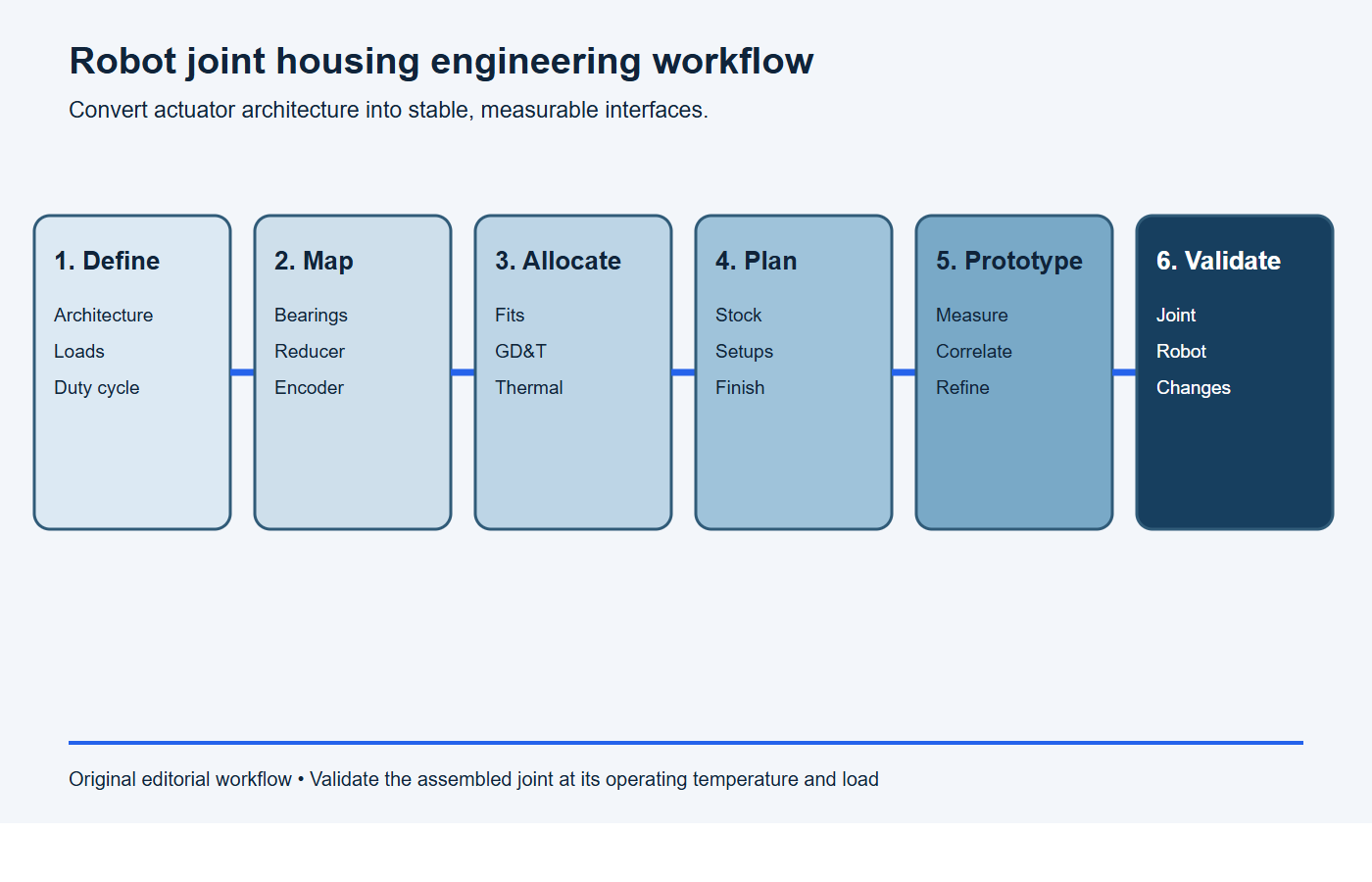
- Define: actuator architecture, loads, duty cycle, environment and performance targets.
- Map: bearing, reducer, motor, encoder, sensor and link datum relationships.
- Allocate: fits, geometric controls, stiffness, thermal paths and verification methods.
- Plan: stock form, machining setups, finishing, assembly and inspection condition.
- Prototype: correlate dimensional, structural and thermal models with representative hardware.
- Validate: test the assembled joint and robot, then control production changes.
What should an RFQ include?
Paste this scope into the RFQ and attach the controlled housing drawing, CAD model, interface drawings and assembled error budget.
RFQ scope: Please quote [robot-joint housing part number and revision] for [prototype quantity] and [annual volume]. The housing locates [bearing, reducer, motor, encoder and link interfaces] and operates under [loads, speed, duty cycle and temperature range]. Quote the proposed stock form, aluminum alloy and temper, machining setup, finish, tooling, unit price, lead time and capacity. State every requested deviation.
Required evidence: Provide material traceability, first-article inspection, bore size and form data, datum-related runout or position results, surface texture and final-finish records, measurement uncertainty for critical features, packaging controls and change-notification triggers. Identify joint- and robot-level tests outside the housing supply scope.
- Matching-revision 3D model and controlled 2D drawing
- Joint architecture and controlled component interface drawings
- Functional datums, bearing arrangement and reducer model
- Loads, speed, duty cycle, life and temperature range
- Alloy, temper, stock route and approved substitutions
- Final-state fits, GD&T, texture, finish and masking
- Free, restrained and assembled inspection conditions
- Prototype, launch and annual quantities with variants
- Required reports, traceability, cleanliness and packaging
- Joint-level validation plan and change-control rules
Stop conditions: the joint housing is not ready for release
Pause tooling or production release if any item below is unresolved.
- the bearing, reducer, motor or encoder interfaces are from mismatched revisions;
- loads, speed, duty cycle, life or operating temperature is missing;
- the datum scheme does not reproduce the assembled joint axis and link interfaces;
- the assembled alignment or runout budget has not been allocated among components;
- bore size is specified without required form, surface condition or final coating state;
- thin-wall distortion, clamping and datum transfer are absent from the process plan;
- the inspection method cannot demonstrate adequate uncertainty for critical controls;
- a housing report is being treated as proof of joint or robot accuracy without system testing.
Share the mating-interface requirements before freezing every machining detail. BAOSONG can review aluminum joint housings for stock selection, datum strategy, tool access, distortion risk, finishing and inspection planning against the supplied product definition. Use the contact page to request an engineering review.
Frequently asked questions
What tolerance should a robot joint housing use?
There is no universal value. Derive each limit from bearing fit, reducer and encoder interfaces, load, stiffness, temperature and assembled performance. Apply tight controls only to characteristics that protect those functions.
Is coaxiality the same as runout?
No. Coaxiality is a functional description, while position and runout controls have specific tolerance-zone and datum meanings. Choose the drawing control that represents function and can be measured reliably.
Does five-axis machining guarantee better coaxiality?
No. It can reduce datum transfers, but machine calibration, rotary error, tool reach, clamping, thermal condition and inspection still determine the result. Some opposing bores are better finished by turning or line boring.
Which aluminum alloy is best for a robot joint housing?
The choice depends on stock route, strength, fatigue, machining stability, corrosion, finish, heat flow and availability. Geometry usually contributes more to stiffness than changing between common aluminum alloys.
Should bearing bores be anodized?
Only if the bearing, fit and finishing specifications support it. Anodizing changes the interface and may affect size, texture and assembly. Many designs mask or post-machine critical seats, but the correct condition is project-specific.
Can a housing inspection report prove robot repeatability?
No. It proves selected component characteristics. Robot repeatability also depends on bearings, reducer, encoder, links, assembly, calibration, controls, payload and temperature, and requires system-level testing.
Recommended Downloads for CNC Machining Design
Use these BAOSONG references to improve tool access, feature geometry, practical tolerances and CNC process planning before release.
- Aluminum CNC Machining Design Guide (PDF)
- CNC Milling Guide: Pockets, Walls, Corners & Tool Access (PDF)
- CNC Turning Guide: Diameters, Threads & Concentric Features (PDF)
- CNC Machining Tolerance Guide (reference sheet)
- Aluminum Part Design Checklist (editable Excel)
Need help reviewing a machined part or feature stack? Contact BAOSONG Precision.
