
Quick answer: how should aluminum components for robot end effectors be manufactured?
Begin with the end effector’s task, robot interface, payload, center of gravity, acceleration, gripping or process loads, utilities, environment and safety functions. Divide the assembly into functional components such as the adapter plate, structural frame, gripper body, fingers, vacuum manifold, sensor brackets and guards. Give each component a manufacturing route and tolerances based on its load path and interfaces.
CNC machining is usually the most flexible route for prototypes and precision interfaces. Extrusion can reduce material removal for rails and repeated frame sections. Die casting can integrate ribs, ports and bosses when stable volume supports tooling. Sheet fabrication suits guards and large covers. Hybrid end-of-arm tooling often combines all four routes.
Control the robot flange pilot and face, tool-center-point datum chain, jaw or cup locations, dowel holes, pneumatic sealing faces and sensor references in their final finished state. Minimize moving mass without sacrificing stiffness, protect cables and hoses, and validate the assembled tool under representative load, motion, loss-of-energy and service conditions.
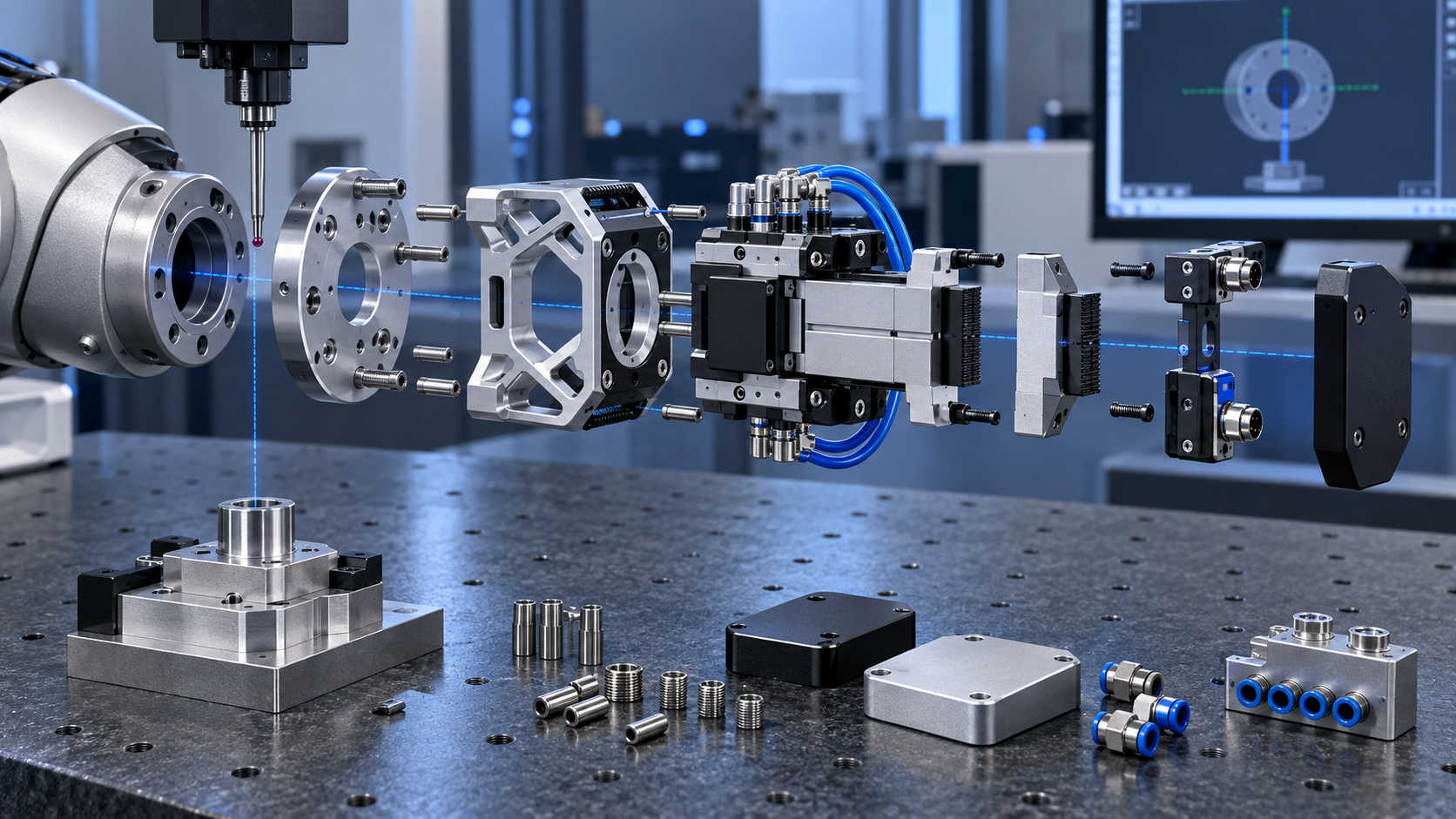
Define the end-effector function before choosing a process
Use this sequence before choosing billet, extrusion or casting:
- Define the task. Record the workpiece range, robot, tool changer, process forces, payload, acceleration, utilities, environment and foreseeable faults.
- Partition the assembly. Give the adapter, frame, gripper body, fingers, manifolds, sensors and guards clear functions and interfaces.
- Map the datum and load chains. Trace the tool center point, contact forces, mass, center of gravity and inertia back to the robot flange.
- Select each process. Match CNC machining, extrusion, casting or sheet fabrication to geometry, revisions, volume and inspection.
- Validate the complete tool. Test gripping or process performance, motion, energy loss, hose and cable behavior, service access and safety functions.
“End effector” includes much more than a parallel gripper. It may be a vacuum tool, welding torch bracket, dispensing head, deburring spindle, inspection sensor, screwdriving unit, tool changer or a multi-function end-of-arm assembly. Each task creates a different combination of accuracy, stiffness, heat, contamination and service requirements.
Record the robot model and wrist interface, rated and dynamic load limits, workpiece mass and variability, tool center point, center of gravity, maximum accelerations, process forces, duty cycle, collision scenarios, utility pressures and electrical connections. Include temperature, dust, moisture, chemicals, food or clean-area requirements, where applicable.
Separate tool performance from robot performance. A precise adapter plate can preserve alignment, but robot calibration, joint stiffness, payload, controls and process forces still influence the delivered tool path. Define acceptance at component, assembled tool and robot-cell levels.
Build a component-to-process matrix
| Component | Critical functions | Candidate route | Key controls |
|---|---|---|---|
| Robot adapter plate | Centers, clocks and transfers load from the wrist | CNC-machined plate, billet or near-net blank | Pilot, face, bolt circle, dowel/clocking and thickness |
| Tooling frame | Maintains cup, jaw or process-head locations under motion | Machined plate, extrusion assembly or fabricated structure | Datums, stiffness, joint slip, flatness and mass distribution |
| Gripper body | Guides jaws and contains actuator or pneumatic passages | Billet machining, extrusion plus CNC or die casting plus CNC | Guide alignment, bore form, sealing faces and port integrity |
| Custom fingers | Contacts and locates the workpiece | CNC machining from bar or plate | Contact geometry, pair symmetry, mounting datum and edge condition |
| Vacuum manifold | Distributes vacuum and supports cups | Machined block, extrusion plus plugs, or cast body | Passage boundary, threads, sealing, cleanliness and leak test |
| Sensor bracket | Preserves target distance and orientation | Machined plate, bent sheet or extrusion | Mounting datum, stiffness, adjustability and cable clearance |
| Guard or cover | Protects users, cables and internal components | Sheet fabrication, extrusion or molded nonmetal part | Edges, access, impact, fasteners and interference envelope |
The matrix keeps precision where it changes function. A sensor bracket may need a controlled reference face while its outer profile remains broadly toleranced. A cosmetic guard may need appearance control but no precision bore.
Use the robot flange standard within its scope
ISO 9409-1:2004 defines the main dimensions, designation and marking for circular plate mechanical interfaces. It supports exchangeability and orientation of hand-mounted end effectors. It does not define the complete coupling device or assign load-carrying capacity. NIST’s robot accuracy and performance assessment workshop illustrates why interface geometry and measured system performance must remain separate questions.
Obtain the robot manufacturer’s controlled wrist drawing and confirm the applicable flange designation, pilot, bolt pattern, clocking, fastener engagement and cable or utility opening. Check whether a tool changer, force-torque sensor or compliance unit sits between the wrist and adapter.
Design the adapter for the actual force and moment envelope. The standardized pattern establishes geometry, while material, thickness, fastener preload, joint friction, dowels and local stiffness determine how the assembly carries load.
Map the tool-center-point datum chain
The robot flange face and pilot commonly begin the datum chain. From there, adapter plates, tool changers, sensors, frames, gripper bodies and fingers each add interface variation. Identify which surfaces locate, which fasteners clamp and which features clock rotation.
Control each component in a functional datum reference frame. A broad mounting face may be primary, a pilot or dowel pair may establish in-plane location, and a clocking feature may remove rotation. Avoid asking clearance bolts to provide precision location unless the design and stack explicitly allow it.
Calculate worst-case or statistical accumulation according to project policy. Include plate flatness, pilot clearance, dowel position, fastener clearance, joint slip, finger mounting and workpiece variation. Reserve robot calibration for residual system error rather than using calibration to hide an unstable mechanical stack.
Calculate mass, center of gravity and inertia
Every gram at the wrist affects the robot load case, especially when it sits far from the flange. Provide the assembled mass, center-of-gravity coordinates and inertia data in the coordinate system required by the robot manufacturer. Include workpiece, hoses, cables, fittings and tool changer.
Reduce mass first where it produces useful leverage: remote covers, fingers and long frame members. Preserve material around the flange, structural joints, actuator mounts and load paths. Large internal pockets can lower mass but increase machining time, thin-wall movement and cleaning difficulty.
Recheck stiffness and natural-frequency behavior after weight reduction. A light frame that deflects under acceleration can move the tool center point even when every unloaded dimension passes inspection.
Design adapter plates for repeatable mounting
Use a continuous, accessible seating face and a pilot or qualified locating system. Provide wrench and tool access, sufficient thread engagement, safe edge distance and a defined installation torque. Prevent fastener heads from interfering with adjacent sensors or moving parts.
Control face flatness and the pilot’s relationship to the face and clocking features. If the adapter has interfaces on both sides, relate them through one datum scheme. A plate can meet thickness limits yet tilt the tool if opposing faces are not controlled.
For automatic tool changers, follow the changer manufacturer’s master/tool plate requirements, locking mechanism and utility module definition. Do not copy an ISO flange pattern into the changer coupling and assume retention, repeatability or fail-safe behavior.
Manufacture gripper bodies around guide and seal functions
A pneumatic or electric gripper body may locate guide rails, piston bores, bearings, jaw carriers and end stops. Determine which feature establishes jaw motion and keep paired guide features aligned within the functional datum frame.
Bore size alone does not control taper, roundness, straightness or surface texture. Seal grooves need width, depth, corner radius, land condition and lead-in appropriate to the selected seal. Cross-drilled passages require a planned closure method and adequate material around ports.
Machine sealing and guide features late enough to protect them from subsequent distortion. Deburr passage intersections without damaging metering edges. Clean and verify the internal flow path before assembly.
Design custom fingers from the workpiece contact
Finger geometry should constrain the part predictably without damage. Define contact pads, nests, serrations or compliant inserts from the workpiece material, surface finish, allowable marks, dimensional variation and expected contamination.
Keep the mounting interface repeatable and distinguish it from the workpiece contact. Replaceable fingers benefit from dowels, shoulders or another positive location when bolt clearance would create unacceptable variation. Add lead-ins that guide the workpiece without sharp edges.
Thin, long fingers amplify deflection and impact load. Use section depth, ribs or shorter reach where the task permits. Simulate the actual gripping and acceleration loads, then validate grip retention and workpiece condition with representative parts.
Integrate vacuum and pneumatic passages safely
Map supply, exhaust, vacuum, blow-off and sensing passages before machining. Separate channels with enough material for pressure and manufacturing variation. Avoid drill breakthroughs into mounting threads or cosmetic surfaces.
Define ports, plugs, sealants, O-rings, thread engagement and leak-test boundaries. A drawing note such as “leak free” is incomplete without medium, pressure or vacuum level, duration, stabilization and acceptance rule. Consider trapped volume and response time where fast pick cycles matter.
Provide drainage or cleaning access where the process can introduce liquid or particles. Confirm material and seal compatibility with the gas, lubricant, cleaner and temperature. The system designer must assess stored pneumatic energy and loss-of-pressure behavior.
Protect sensors, cables and hoses
Locate presence sensors, cameras, force-torque sensors and switches on stiff references with adjustment where calibration requires it. Keep brackets out of the collision envelope and support cable connectors against repeated bending.
Route hoses and cables through the full wrist motion, including tool changes and service positions. Provide bend radius, strain relief and abrasion protection. Clamps should restrain utilities without crushing tubing or loading precision sensor bodies.
Machined channels and covers can organize utilities, but avoid sharp internal edges and inaccessible pinch points. Ensure covers can be removed without disturbing calibrated components.
Treat end-effector safety as a system requirement
ISO/TR 20218-1:2018 provides safety guidance for the design, manufacturing and integration of end effectors used in robot systems. ISO 10218-2:2025 addresses integration, commissioning, operation and maintenance of industrial robot applications and cells within its scope. The design review must cover setup, testing, adjustment and maintenance as well as normal automatic operation. NIST’s robotic-systems performance assessment framework demonstrates the value of defined metrics and system models for evaluating integrated tasks.
The risk assessment must consider sharp edges, crushing and shearing zones, ejected workpieces, dropped loads, tool release, stored energy, hot surfaces, process hazards and foreseeable misuse. These requirements can change guards, retention features, energy isolation and inspection access.
A material certificate or dimensional report for an aluminum component does not certify the end effector or robot cell. Validate the assembled tooling and safeguards in the intended application with the responsible integrator.
NIST’s review of industrial-robot evaluation and benchmarking explains the value of common measures and test methods for characterizing capabilities. Translate that principle into task-specific acceptance tests for the assembled end effector.
Choose an aluminum alloy from the complete requirement
Consider strength, fatigue, stiffness geometry, machinability, residual stress, corrosion, anodizing response, thermal behavior, contact wear and stock availability. High nominal strength does not compensate for poor load paths, and aluminum alloys have similar elastic modulus compared with the differences in their strength.
Machined plate or billet supports rapid design changes. Stress-relieved stock may improve stability for heavily pocketed frames. Extrusion alloys suit rails and repeated sections. Casting alloys support integrated bodies but have different mechanical and finishing behavior.
Use BAOSONG’s aluminum alloy selection guide, 6061 versus 6063 comparison and 6061-T6 versus 7075-T651 guide as starting points, then qualify the exact alloy and temper for the tool.
Select the manufacturing route by geometry and volume
| Route | Best starting point | Main benefits | Engineering limits |
|---|---|---|---|
| CNC machining | Prototypes, low volume and precision interfaces | Fast iteration, local accuracy and flexible geometry | Material removal, tool reach, setup count and cycle time |
| Extrusion plus CNC | Rails, beams, manifold bodies and repeated sections | Integrated channels/bosses with reduced cutting | Constant cross-section, die cost and profile tolerances |
| Die casting plus CNC | Stable-volume gripper bodies and covers | Integrated ribs, passages, bosses and thin walls | Tooling, draft, porosity, alloy and design-change cost |
| Sheet fabrication | Guards, trays and broad lightweight structures | Low mass, scalable envelope and modest tooling | Bend/weld variation, edge safety and joint stiffness |
Hybrid construction frequently gives the best result. Compare the accepted assembly, including tooling, secondary machining, joining, finishing, inspection and revision risk. BAOSONG’s guide to extrusion, CNC machining and die casting expands this comparison.
Apply CNC design rules to reduce time and risk
Use standard tool access, practical internal radii and pocket depths, and avoid thin walls that have no structural purpose. Give cutters and probes access to critical faces. Separate cosmetic skins from highly machined structures where that simplifies both processes.
Plan which features belong in one setup. Machining the flange pilot, reference face and critical dowel holes in a controlled orientation can protect their relationship. Multi-axis positioning can reach angled ports and several faces, but machine calibration, rotary error, workholding and tool projection still matter.
Review lower-cost CNC part design, multi-axis aluminum machining and practical aluminum CNC tolerances before release.
Control thin walls and lightweight pockets
Long frames and pocketed plates can vibrate during cutting, move when clamps release and distort after finish or assembly. Keep section changes gradual, use ribs along load paths and leave material around threaded joints, dowels and actuator mounts.
Rough symmetrically where possible and leave stock for finish passes on critical faces. Use fixtures that support the part without forcing it flat. If the end effector is inspected in an assembled or clamped condition, define the hardware, torque and sequence.
Do not optimize only the component mass. Added pockets may increase machining time and reduce cleanability while saving little robot inertia if they sit close to the wrist. Evaluate mass distribution and total cost.
Specify GD&T from function
Use size controls for fits, form controls where local shape matters, orientation and position for datum-related interfaces, and runout where rotating behavior is relevant. Avoid a general ±0.01 mm note across the drawing; it can overcontrol clearance features and still miss a critical flange relationship.
ASME Y14.5-2018 (R2024) establishes symbols and rules for communicating GD&T. Select the drawing standard, datum scheme, modifiers and inspection interpretation consistently.
Define the final-state condition. Anodizing, inserted bushings, fastener preload and bonded pads can change size or geometry. If a functional feature is accepted after finishing and assembly, state that requirement directly.
Plan finishing, wear surfaces and electrical contact
Anodizing can improve corrosion and wear behavior and provide a controlled appearance, but it changes dimensions and electrical contact. Mask locating bores, ground paths, seal lands, bonded areas and threads where the design requires another condition. Locate rack marks in approved zones.
Use replaceable steel, polymer or hardened contact elements where jaws see repeated abrasion. Avoid asking decorative anodizing to serve as an undefined bearing surface. Specify coating type, color, texture, thickness or class as applicable, sealing, acceptable variation and approved samples.
BAOSONG’s anodized aluminum and surface-finishing pages provide process context. Coordinate finishing with tolerance and assembly requirements before ordering parts.
Clean, assemble and protect the components
Remove chips and abrasive media from vacuum passages, threaded holes, guide pockets and sensor cavities. Define cleanliness by the process risk: a general industrial gripper, paint tool, optical inspection head and food-contact tool require different controls.
Use controlled fastener grades, locking methods, lubricants or thread treatments, torque and sequence. Prevent mixed hardware from creating galvanic or service problems. Record critical assembly settings where field replacement must reproduce alignment.
Protect finished surfaces with clean separators and purpose-designed trays. Cap pneumatic ports and protect pilots, dowels and sharp jaw features during shipment. Packaging must not trap moisture or leave adhesive residue on contact surfaces.
Match inspection to the requirement
| Requirement | Possible method | Test condition | Additional proof needed |
|---|---|---|---|
| Flange pilot and face | CMM, bore measurement and surface method | Final finish, stated support and reference temperature | Mounted tool-center-point verification |
| Dowel and hole pattern | CMM or functional checking fixture | Functional datum realization | Assembly and interchange trial |
| Jaw/contact location | CMM, optical or dedicated fixture | Specified open/closed and preload state | Representative workpiece grip trial |
| Passage integrity | Pressure, vacuum, flow or leak test | Defined medium, level, duration and boundary | Cycle response in assembled tool |
| Frame deflection | Load fixture, indicators or optical measurement | Specified force/moment and mounting | Dynamic robot-motion validation |
| Mass properties | Scale and center-of-gravity/inertia method | Complete tool with utilities and hardware | Robot configuration entry and motion trial |
NIST’s paper on dimensional calibration uncertainty explains that a measurement is an estimate with uncertainty. Use calibrated equipment, suitable resolution, a defined support condition and uncertainty appropriate to the acceptance decision.
Validate the assembled end effector
Test grip or process force, workpiece retention, tool-center-point stability, structural deflection, pneumatic response, sensor function, cable behavior, temperature and service cycles. Use representative workpieces across their allowed variation and the robot’s intended motion profile.
Include loss of air, electrical power or control signal as required by the risk assessment. Verify tool-change locking and utility connection, fastener retention, guards and recovery after faults. Record the tested configuration and control design changes that can affect it.
Component dimensional acceptance supports manufacturing quality. The system integrator remains responsible for assessing the end effector, robot, application and safeguards together.
Use this manufacturing workflow
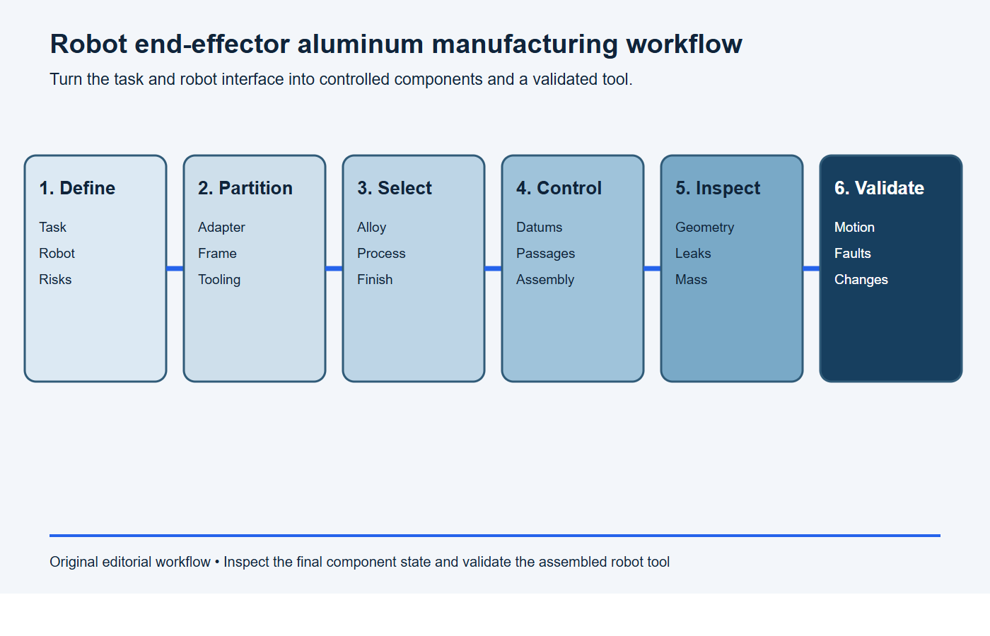
- Define: task, workpiece, robot, loads, utilities, environment and risks.
- Partition: adapter, frame, gripper, fingers, manifold, sensors and guards.
- Select: alloy, stock form, machining, extrusion, casting or sheet route.
- Control: datums, tolerances, passages, finish, cleanliness and assembly.
- Inspect: final-state dimensions, leaks, mass properties and documentation.
- Validate: the assembled tool through representative robot motions and fault conditions.
What should an RFQ include?
Paste this scope into the RFQ and attach the controlled assembly model, component drawings, robot wrist drawing and risk-assessment inputs.
RFQ scope: Please quote [end-effector assembly or component revision] for [prototype quantity] and [annual volume]. The tool performs [task] on [workpiece range] using [robot and tool changer] under [forces, payload, acceleration and duty cycle]. Quote the proposed component split, aluminum alloys, manufacturing routes, finishes, tooling, unit price, lead time and capacity. State all assumptions and deviations.
Required evidence: Provide material traceability, component and assembly inspection, mass/center-of-gravity data, pneumatic or vacuum leak results, final-finish records, cleanliness, first-article documentation, packaging controls and change-notification triggers. Identify robot-cell validation and safety activities outside the component supply scope.
- Matching 3D models, controlled drawings and assembly structure
- Robot model, wrist drawing, tool changer and sensor interfaces
- Workpiece range, grip or process force, payload and dynamic loads
- Tool-center-point, center-of-gravity and inertia requirements
- Alloy, temper, finish, masking and appearance zones
- Functional datums, critical fits, GD&T and final-state condition
- Vacuum/pneumatic schematics, ports and leak-test criteria
- Prototype, launch and annual quantities with expected revisions
- Inspection reports, traceability, cleanliness and packaging
- Assembly and application validation responsibilities
Stop conditions: the end-effector components are not ready for release
Pause tooling or production release if any item below remains unresolved.
- the robot, wrist interface, tool changer or component revisions do not match;
- payload, center of gravity, inertia, acceleration or external loads are missing;
- the tool-center-point datum chain and locating method are undefined;
- grip, vacuum or process-force acceptance criteria are not measurable;
- hose, cable, sensor and stored-energy behavior has not been reviewed through the full motion range;
- critical passages, seals or cross-drill closures lack cleaning and leak-test requirements;
- finish state, wear surfaces, masking and electrical contacts are unclear;
- component inspection is being used as proof of assembled tool or robot-cell safety.
Provide the functional stack before freezing manufacturing details. BAOSONG can review aluminum adapter plates, frames, gripper bodies, fingers and manifolds for process selection, tool access, distortion, finishing and inspection. Use the contact page to request a drawing-based engineering review.
Frequently asked questions
Is CNC machining the best process for every aluminum end-effector part?
No. It is flexible for prototypes and precision interfaces. Extrusion can suit repeated rails and manifolds, casting can integrate stable-volume bodies, and sheet fabrication can reduce guard and frame mass.
Does an ISO 9409-1 pattern prove the adapter can carry the load?
No. The standard defines interface geometry within its scope. Load capacity still depends on the selected interface, material, thickness, fasteners, preload, joint design and application loads.
Which aluminum alloy should be used for gripper fingers?
Select it from finger load, fatigue, stiffness geometry, wear insert, machining, corrosion and finish needs. Contact pads or replaceable inserts may be more important than choosing the highest-strength aluminum.
How should the tool center point be controlled?
Build a datum chain from the robot flange through every adapter and tooling interface to the contact or process point. Control locating features mechanically, measure the assembled tool and calibrate the remaining system offset.
Should anodized dimensions be measured before or after finishing?
The drawing should state the functional final condition. Critical fits, pilots and seal lands may be masked or post-machined, while other surfaces may be accepted after anodizing.
Can a CMM report certify the end effector as safe?
No. It verifies specified dimensions. Safety also depends on grip retention, energy loss, guards, controls, integration, robot motion, workpiece and foreseeable use, which require system-level assessment.
Recommended Downloads for CNC Machining Design
Use these BAOSONG references to improve tool access, feature geometry, practical tolerances and CNC process planning before release.
- Aluminum CNC Machining Design Guide (PDF)
- CNC Milling Guide: Pockets, Walls, Corners & Tool Access (PDF)
- CNC Turning Guide: Diameters, Threads & Concentric Features (PDF)
- CNC Machining Tolerance Guide (reference sheet)
- Aluminum Part Design Checklist (editable Excel)
Need help reviewing a machined part or feature stack? Contact BAOSONG Precision.
