
Quick answer: custom aluminum on-board charger housings
BAOSONG develops and manufactures custom aluminum on-board charger housings that combine electronics mounting, heat removal and vehicle installation. For a liquid-cooled OBC, we recommend a separate cold plate when the cooler needs independent servicing or design changes. An integrated coolant base suits a compact package where removing an extra base-to-cooler joint is worth the more involved closure and inspection work. The body can be machined or cast and finish-machined to suit the geometry and order volume.
We set the PCB supports and device contact areas together, then position the connectors, cover seal and coolant ports. The electronics cavity and coolant circuit have different seals and test requirements. Keeping those details explicit prevents a housing that fits externally but bends the board, misses thermal contact or leaves no room to connect a hose.
Send BAOSONG a board layout, housing drawing or sample photo. We will propose the body and cooling construction, identify any fit problems, and quote the parts or mechanical assembly you need. Approved drawings can go straight into manufacturing review and quotation.
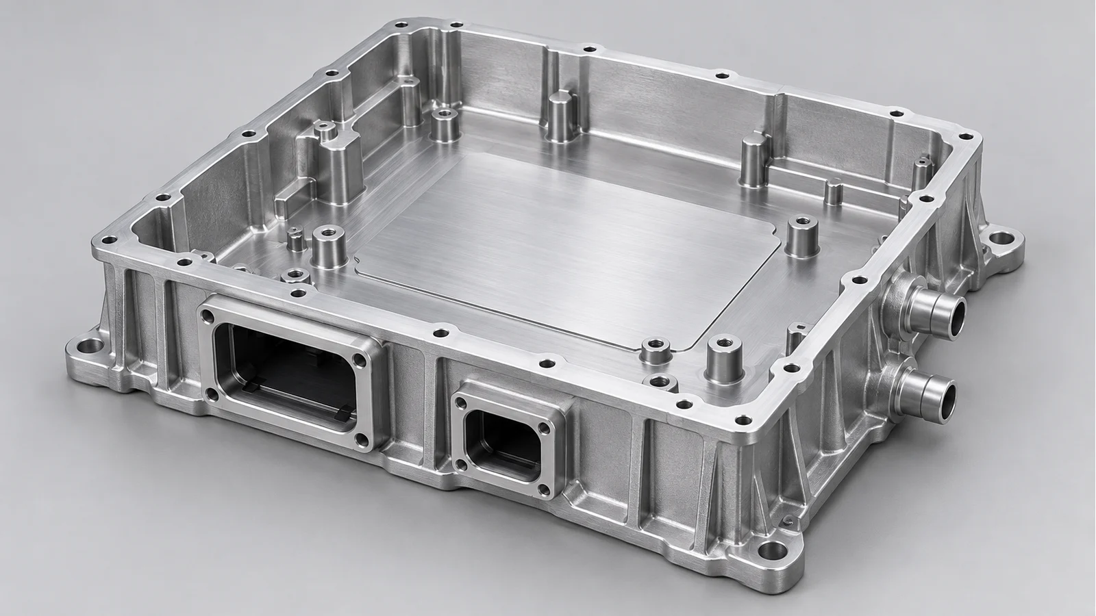
On-board charger housings at a glance
| Your project condition | BAOSONG recommendation | Decision to release |
|---|---|---|
| Board or connector layout is changing | Machined base and coordinated cover where suitable | Support heights, thermal regions and accessible machining features |
| Stable geometry integrates many ribs and bosses | Cast body with selective CNC finishing when justified | Tooling scope, casting stock and functional inspection |
| Devices contact the base through a thermal pad | Review the complete support/device/interface stack | Gap range, selected material and permitted assembly loading |
| One body serves OBC and other power functions | Coordinate each zone and the shared housing interfaces | Board access, heat paths, electrical space and connector relationship |
| Liquid cooling in a tight package | Compare a replaceable cold plate with an integrated coolant base | Available height, heat path, port support and separate enclosure/coolant seals |
What does an on-board charger housing supply include?
An on-board charger housing carries the charging electronics installed in the vehicle. The OBC converts grid AC to the DC used to charge the traction battery, as shown in Valeo’s description of an on-board charger. BAOSONG supplies the body, cover, thermal base and specified mechanical components, separately or as an agreed assembly.
An EV charger electronics housing can describe several products. Here it means the vehicle OBC module enclosure, not a complete charger, traction inverter or roadside cabinet. For an off-board EV charging station enclosure, see our aluminum charging-station enclosure guide. Keeping those boundaries clear makes the drawings, manufacturing proposal and acceptance requirements comparable.
An OBC housing for EV applications may also share a package with a DC/DC converter or other power functions. For a shared mechanical body, we coordinate each electronics zone and its interfaces without treating the complete electrical system as part of an empty-housing quotation.
Why use aluminum for a custom charger housing?
An aluminum charger housing can combine low mass, a useful heat-conduction path and integrated mounting features. Local machining establishes the surfaces that support devices, locate the board, close the cover or receive connectors. The aim is to make the enclosure and thermal structure work together, reducing unnecessary brackets or interface parts where the approved design allows it.
We select the alloy and product form with the chosen construction. A cast body can integrate ribs and bosses; a machined base offers flexible local geometry; a suitable extrusion can repeat a constant section. Material selection also considers joining, finish and contact with the cooling system. A convenient alloy designation alone does not define the finished housing’s thermal or structural behavior.
Choose a construction that matches the OBC layout
Choose the cooling arrangement before committing the body to a manufacturing route. If the board layout is changing, a machined base allows local supports and contact pads to move without a new mold. For a stable body with many ribs and bosses, casting plus local CNC finishing can reduce repeated material removal. CNC machining can also serve recurring orders when the geometry and order quantity support it.
| Construction | Choose it when | Tradeoff and change trigger | BAOSONG release |
|---|---|---|---|
| Machined base/body and cover | Layout flexibility and accessible critical interfaces dominate | Deep pockets and thin features can increase processing effort. Compare near-net construction once geometry and recurring demand stabilize. | Support strategy, reference features, cover relationship and finishing state. |
| Cast body plus local CNC finishing | Stable complex ribs, bosses and enclosure geometry justify tooling | Tooling, casting integrity and machining access need early decisions. A board or connector move may affect more than a local cutout. | Cast/machined feature map, stock allowance and finished interface acceptance. |
| Finned extrusion or fabricated construction | The section and assembly suit the design, with a viable heat-removal path | Fins need usable airflow and installation clearance. Separate joints and end features add interfaces. Reassess if packaging or cooling conflicts. | Section/access review, end interfaces, heat-path assumptions and sealing scope. |
For aluminum CNC machining, we choose fixture references that keep the support heights, device pads and connector openings in their required positions. Deep pockets need cutter access; thin walls need support during cutting. Those details belong in the manufacturing proposal before the first body is made.
Set the PCB supports and thermal contact together
The PCB supports set the board position. The device package determines the height of its underside above the aluminum base. We calculate the remaining gap from those assembled dimensions, including their tolerances, and match it to the selected thermal interface material. Support heights and contact pads are then dimensioned together on the housing drawing.
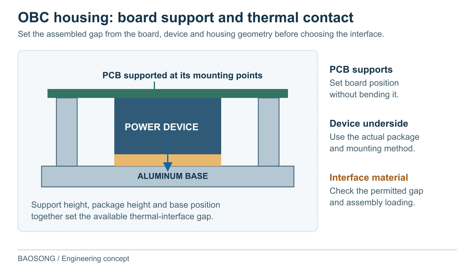
A thicker pad is not an automatic correction for an uncertain gap. It can change compression, force on components and the heat-transfer path. We first review the minimum and maximum assembled gap, the selected material and the supported board condition, then propose the housing features that keep the interface within its approved working range.
Henkel’s BERGQUIST GAP PAD TGP HC5000 technical data sheet notes that actual application performance depends on surface roughness, flatness and applied pressure. BAOSONG therefore specifies the contact area, support relationship and delivered surface condition together.
Separate cold plate or integrated coolant base?
Use a separate cold plate when the housing and cooler need different replacement or revision cycles. The plate can bolt beneath a closed housing base, which adds a thermal contact joint, or form the floor of the electronics enclosure with a gasket around its perimeter. We recommend the floor arrangement when the package needs fewer thermal joints and the enclosure can seal around the plate. The board mounts and connectors remain referenced to that floor.
Use an integrated coolant base when height and part count drive the design. The device contact face and coolant-channel wall become part of the same housing base. We arrange channels beneath the relevant heat-source areas, position ports where the hoses can be fitted, and select the channel-cover joint with the material and production route. The gain is a more integrated package; cooler repairs or channel changes may then affect the housing itself.
Boyd’s cold-plate construction guide shows several channel and joining approaches, including vacuum-brazed aluminum constructions. These are route options, not interchangeable specifications. Our proposal identifies the selected joint, coolant compatibility and thermal/hydraulic conditions for the OBC design.
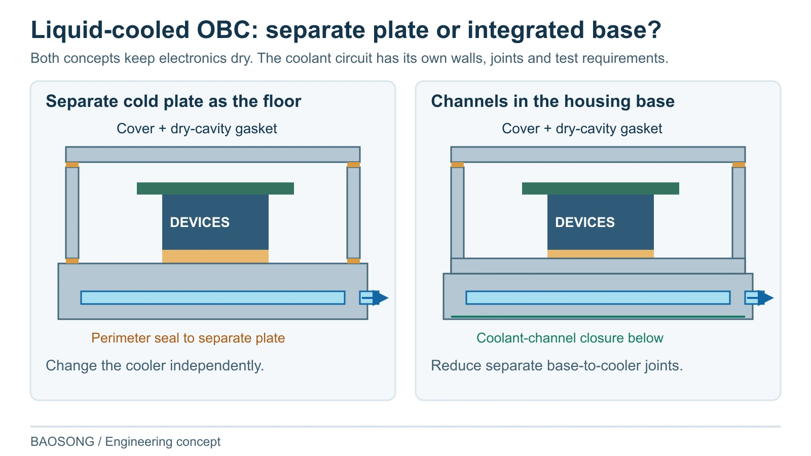
Keep the two sealing tasks separate. The cover gasket protects the dry electronics cavity. The channel cover, ports and their joints contain pressurized coolant. A successful cover-seal check does not establish coolant tightness. We specify separate test objects and acceptance conditions for the enclosure and the coolant circuit.
Plan any joining that can distort the base before final machining of the critical contact surfaces, with enough stock and tool access to finish them. Deburr and clean the channels before closure; check the closed circuit by the agreed method. Give hose connections a supported mounting region and room for the fitting tool, so installation loads are not carried by a thin wall. Functional faces receive the specified finish or masking.
For an air-cooled OBC, we recommend a finned body only when the installed location provides a usable air path. The loss map, local air temperature and vehicle packaging determine whether this route is viable. A sheltered space with poor airflow needs a different heat-removal arrangement, even if external fins fit the housing.
Coordinate connector installation, board access and cover closure
We locate connector openings against the board and installed harness arrangement, not just the outer wall. The review checks insertion direction, fastener access, seal seating and support for the specified harness load. Mechanical clearance must also preserve the electrical space allocated by the electronics design.
The cover and seal need their own controlled relationship. We review the gasket path, seating features and fastener layout with the board’s component envelope. Cover closure should follow the intended load path rather than press on a component or bend the board to achieve contact. Potting, bonding or encapsulation, when specified, also enters the assembly and service-access review.
How BAOSONG addresses the OBC problems that appear at assembly
| Buyer problem | BAOSONG action | Mechanism | Customer output |
|---|---|---|---|
| Board fits but thermal contact is inconsistent | Review support height, device envelope and interface gap together | Contact is evaluated over the assembled stack, not the base face alone. | Released stack and critical housing features. |
| A connector revision conflicts with the housing | Move the opening or its support to preserve insertion and tool access. | Harness loads are supported at the connector wall. | Revised sidewall and connector-seat details. |
| Cover sealing disturbs electronics | Change the cover clearance, gasket seat or fastener support as required. | Cover loading follows its fasteners and seal, without pressing on the board. | A cover arrangement with component clearance shown. |
| Surface treatment changes a functional interface | Specify coating or masking by surface and measure critical finished features. | The delivered contact or fit is checked after the relevant process. | Surface notes and finished-part measurements. |
Inspect the OBC housing in the condition that will be delivered
State the functional references, material condition and finishing stage for the inspected features. A dimensional result before coating does not establish a specified after-treatment fit. Where a coolant circuit or complete mechanical enclosure is included, its test object, closures and acceptance conditions are agreed separately from the board-support dimensional report.
| Interface | Define before inspection | Evidence to agree | Review again when |
|---|---|---|---|
| Board supports and thermal surfaces | References, support heights, contact areas and assembled-gap assumptions | Dimensional and surface results tied to the released drawing | Board, device, pad or base geometry changes |
| Connector and mounting features | Installed location, seating, access and delivered finish | Feature inspection with the mating-interface basis | Connector, harness or mounting arrangement changes |
| Cover and environmental seal | Cover/gasket/fastener configuration and functional surfaces | Specified assembled-boundary assessment where required | Gasket, cover, fastener or finish changes |
| Coolant-containing construction | Material/ports/joints, closure condition and agreed method | Specified leak/pressure/flow evidence where required | Joint, wall, coolant or port arrangement changes |
BAOSONG links these requirements to the project quality and inspection plan. Electrical insulation, EMC, thermal performance and vehicle-level approval need the assigned assembled-system evaluations. We define the component evidence and the wider validation responsibilities together so a mechanical report is used for the question it actually answers.
Keep board revisions controlled through mass production
For mass production, release the board/component envelope, housing construction, thermal interface assumptions, connector arrangement, finish and inspection baseline together. A board revision that leaves the outer envelope unchanged can still alter a device height or heat-source location. We review those effects before carrying the previous housing approval into the revised order.
Approved drawings can proceed directly to quotation. For a supplier transfer, we compare the drawing with the accepted sample and inspection records, then identify any differences in the proposed route. For a new design, the sample plan addresses the remaining questions, such as device contact, connector access or the coolant closure.
If the route changes from a machined body to a casting, BAOSONG identifies the affected material, wall, support, joint and surface conditions. The change record states which earlier evidence remains relevant and which features or functions need renewed review. This keeps continuing supply tied to the actual production construction.
Why choose BAOSONG for your on-board charger housing?
Bring us the board layout and the housing requirements. Our engineering and manufacturing support works through the board supports, contact pads, cooling construction and connector access before those choices become tooling or assembly problems.
| Your priority | BAOSONG action | What you receive |
|---|---|---|
| A housing that fits the real electronics | Coordinate supports, devices, connectors and cover envelope | An interface map and practical manufacturing direction. |
| A thermal base matched to the layout | Locate device contact pads, compare separate and integrated cooling, and provide access to the ports. | A recommended base construction with contact, port and seal details marked on the drawing. |
| Comparable quotations | Name components, finishing, joining and inspection in the delivered scope | A proposal aligned with your assembly needs. |
| Repeat supply after revisions | Check changed device heights, connectors and cooling details against the approved housing. | A list of changed features and the measurements or tests required for the new revision. |
Request an on-board charger housing quote
Send your drawing, board layout or sample photo for an on-board charger housing quote. BAOSONG will recommend the mechanical construction and provide a formal price based on the included parts, material, quantity and inspection requirements.
OBC housing manufacturing questions
Can an existing enclosure be adapted for an OBC?
Yes, when its envelope, thermal base, connectors and mounting arrangement suit the design. We check the functional interfaces before recommending adaptation. If the existing section forces excessive thermal gaps, awkward connector installation or unsuitable sealing, a custom body or base is the more useful starting point.
Must a CNC housing be replaced by casting for repeat orders?
No. CNC machining can serve recurring orders when the geometry, stock use and production requirements support it. Casting is compared when stable complexity and demand justify its tooling and verification, rather than treated as a compulsory final stage.
What should you compare when sourcing an OBC housing from China?
Compare the same drawing revision, board and device envelope, material, cooling construction, finish and inspection requirements. Check whether the offer includes the cold plate, channel closure, cover, seals and coolant-circuit testing. BAOSONG lists these items in the quotation so a bare body is not compared with a completed mechanical assembly.
Start with the information you already have
| What you have | BAOSONG does next | What you receive |
|---|---|---|
| Released housing drawing | Review route, interfaces and inspection scope | Manufacturing proposal and formal quotation scope. |
| Board layout and component envelope | Position supports, device pads and connector openings; recommend the cooling-base construction. | Marked-up geometry for the housing design. |
| Sample or assembly-problem photos | Locate the contact, fit or access problem and propose the affected feature changes. | A specific correction to discuss against the actual assembly. |
| Existing source or repeat-order revision | Compare the accepted files with the proposed part and production route. | Identified differences and an agreed first-article inspection scope. |
Request your custom aluminum on-board charger housing proposal and quote. Send a drawing, layout, sample photo or short description. BAOSONG will turn the board, cooling and enclosure requirements into a manufacturing plan for your aluminum EV electronics project.