
Quick answer: when is an aluminum frame suitable for automated production equipment?
An aluminum frame is a strong candidate when the equipment benefits from modular construction, low moving or installed mass, corrosion resistance, clean cable routing and fast reconfiguration. It is commonly used for assembly cells, inspection stations, conveyors, light gantries, guarding, fixtures and machine modules. Suitability still depends on load, stiffness, vibration, joint behavior, floor anchoring and the required process accuracy.
Design the frame from the equipment load paths and datum structure. Separate members that carry static and dynamic loads from panels that guard hazards and plates that locate robots, rails, cameras or tooling. Size profile sections and joints from deflection and natural-frequency targets, not only strength. Machine critical interfaces after the structural concept is stable.
Validate the assembled frame in its installed condition with leveling feet or anchors, production hardware, utilities and moving equipment. Check geometry under load, joint slip, vibration, guarding, service access and changeover. Extrusion catalog data and individual component inspection support the design but do not prove machine-level precision or safety.
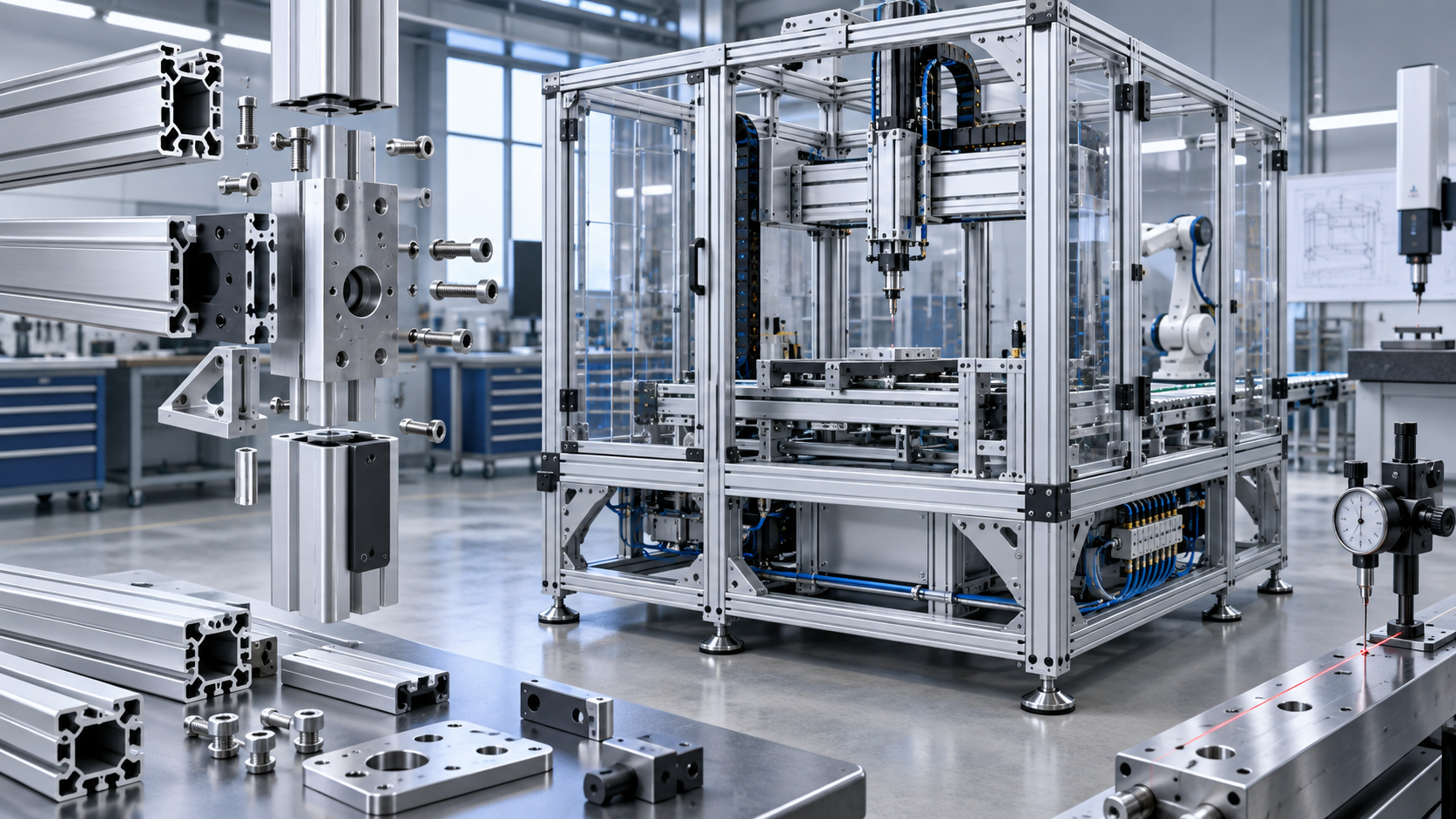
Begin with the machine function and installation
Use this sequence before selecting a profile series:
- Define the process and installation. Record equipment, motion, production loads, hazards, environment, floor, transport and future changes.
- Map load paths and functional datums. Connect robots, rails, cameras, tooling and conveyors through the frame to feet or anchors.
- Set measurable structural targets. Specify allowable relative deflection, vibration, stability and installed geometry at the process point.
- Select profiles and joints as an assembly. Compare T-slot, custom extrusion, machined plates and welded elements with real joint compliance.
- Commission in production condition. Level, anchor, align and test the loaded frame with guards, utilities and moving equipment installed.
Define what the equipment does, the cycle time, process forces, moving masses, acceleration, robot or gantry envelope, product flow and operator interaction. Record installed footprint, transport limits, floor condition, anchoring permissions, ambient temperature, washdown or chemical exposure and expected future expansion.
List static loads from cabinets, conveyors, hoppers and tooling. Add dynamic reactions from indexers, robots, presses, cylinders and emergency stops. Include maintenance loads, doors, cable carriers, material jams and foreseeable misuse identified by the machine risk assessment.
ISO 12100:2010 provides principles and a methodology for machinery risk assessment and risk reduction. Apply the released edition required by the project rather than assuming the frame drawing alone completes the assessment. NIST’s robotic-systems performance assessment framework shows the value of defined metrics and system models when evaluating integrated automated tasks.
Create a frame requirement matrix
| Requirement | Design inputs | Frame controls | Evidence |
|---|---|---|---|
| Static geometry | Equipment weights, spans and allowable displacement | Profile section, bracing, plates, feet and anchors | Analysis and loaded alignment survey |
| Dynamic response | Motion profiles, forcing frequencies and process sensitivity | Stiffness, joint design, mass distribution and isolation | Modal/response model and measured vibration |
| Precision interfaces | Robot, rail, camera, tooling and conveyor datums | Machined pads, dowels, adjustment and tolerance stack | Datum-based inspection and process capability trial |
| Safety | Hazards, access, reach, ejection and maintenance tasks | Guard supports, doors, interlocks, panels and safe distances | Risk assessment and installed safeguarding validation |
| Utilities | Power, controls, air, vacuum, coolant and data | Raceways, trays, glands, manifolds and strain relief | Routing inspection and service trial |
| Environment | Dust, moisture, cleaners, temperature and corrosion | Alloy, finish, drainage, enclosures and compatible hardware | Material/finish records and environmental checks |
Separate strength, stiffness and stability
Strength checks whether stress and connection loads stay within the qualified design basis. Stiffness controls displacement and angular error. Stability addresses member buckling, frame racking and overturning. Automated equipment often reaches its accuracy or vibration limit before an aluminum member reaches its strength limit.
Use section depth, closed cells, cross-bracing and short load paths to increase stiffness efficiently. Place columns and beams under the equipment reactions rather than routing loads through long cantilevers. Check local bearing and pull-out around brackets, T-nuts, anchors and machined plates.
Include joint compliance in analysis. Treating every bolted corner as perfectly rigid can overpredict frame stiffness. Use supplier joint data or representative tests where critical, and verify the complete assembled structure.
Design for static deflection at the process point
Translate frame movement into its effect on the product, sensor or tool. A small base deflection can create a larger angular error at the end of a tall camera mast or robot pedestal. Define allowable relative displacement between functional elements rather than one arbitrary frame-wide number.
Evaluate gravity, payload range, cable-carrier forces and changing product locations. Include floor and foot compliance. If the machine must be movable, compare caster, retractable wheel and fixed-foot conditions separately.
Measure the installed geometry under the load state used in production. An unloaded factory inspection may not represent the frame after cabinets, guarding and automation modules are installed.
Control vibration and resonance
Dynamic behavior depends on mass, stiffness, damping, joints, floor support and forcing frequency. Aluminum’s low density can help moving structures, while modular joints and lightweight panels can create modes that interact with high-speed axes, robots or presses.
Estimate natural frequencies and forced response using realistic joint and support assumptions. Compare them with motor, belt, ball-screw, indexing and cycle frequencies, including harmonics and changing payload. Add stiffness or change mass distribution where separation is inadequate.
Isolation mounts reduce transmitted vibration only when selected for the supported mass and frequency range; they also allow movement. Damping treatments can reduce response but do not replace a continuous load path. Correlate the model with accelerometer or displacement data on the assembled machine.
Choose between modular T-slot and custom extrusions
Catalog T-slot systems support fast assembly and later changes. Their standardized slots accept brackets, nuts, panels and utilities. Custom profiles can place material along the actual load path, integrate cable ducts, panel seats, locating grooves and closed cells, and reduce part count at repeat volume.
Custom extrusion introduces die investment, minimum runs, profile-development time and section-specific tolerances. The Aluminum Extruders Council design resources cover alloy, profile, fabrication and tolerance considerations. AEC’s tolerance guidance also distinguishes standard extrusion tolerances from tighter, supplier-reviewed requirements.
Use BAOSONG’s custom aluminum extrusion guide and profile manufacturability guide when a dedicated section may reduce brackets or machining.
Select profile size from the assembled structure
Profile series labels do not define machine capability. Compare the actual cross-section properties, unsupported length, connection method, orientation and load. A profile can resist bending strongly about one axis and poorly about the other.
Keep spans short and align the strong section axis with the dominant moment. Use paired members, gussets or closed frames where torsion and racking matter. Avoid long unsupported panel rails carrying doors, monitors or pneumatic equipment.
Review deflection at fastener slots and open faces. The nominal member may be stiff while the connection wall crushes or slips. Prototype critical joints if catalog data does not cover the load direction and assembly.
Design joints to transfer force without slip
Possible joints include external corner brackets, internal anchors, end fasteners, gusset plates, dowels, keys and welded connections. Select them from force direction, moment, access, appearance, adjustability and service needs.
Friction-clamped joints depend on clean surfaces, fastener preload and installation torque. Direct-bearing features such as keys, shoulders or dowels can control shear and repeatable location where slip is unacceptable. Do not expect clearance bolts alone to locate precision modules.
Define fastener grade, engagement, washers, locking method, torque and inspection. Recheck after shipping and commissioning where settling may change preload. Avoid inaccessible fasteners behind panels or cable trays.
Use machined plates for precision interfaces
Robots, linear rails, vision systems, nests and metrology devices often need flatter and more repeatable interfaces than an as-extruded face provides. Add machined adapter plates or machine the assembled base where required by the alignment strategy.
Create a functional datum scheme connecting the machine base, motion axes and process tooling. Use dowels, pilots, keys or qualified adjustment features for location. Give indicators, probes and alignment tools access to the reference surfaces.
State whether flatness, parallelism and position apply before or after assembly and under what support condition. ASME Y14.5-2018 (R2024) provides the GD&T language for communicating datum-related geometric requirements.
BAOSONG’s extrusion plus CNC machining guide explains when near-net sections and machined interfaces can reduce material removal.
Allocate tolerances across extrusion, cutting and assembly
Extruded profile variation, cut length and squareness, hole location, plate geometry, bracket clearance and joint slip all enter the stack. Do not apply CNC tolerances to every as-extruded surface. Identify which features can float and which establish the process coordinate system.
Use adjustment where commissioning requires it, with controlled range and a locking method that preserves the final position. Shims, jack screws and slotted holes need defined access and acceptance, not improvised correction.
Review aluminum extrusion tolerances and practical CNC machining tolerances as separate process domains.
Plan leveling, anchoring and floor interfaces
Leveling feet accommodate floor variation but introduce compliance. Anchors resist sliding, uplift and overturning but can distort a frame if tightened against an uneven floor. Define grout, sole plates, shims or isolation as the installation requires.
Place feet under primary load paths and provide wrench access. Check concentrated floor pressure and anchor edge distance. For linked modules, define whether frames share datums rigidly or allow controlled relative movement.
Document leveling sequence, target geometry, anchor torque and final survey. Recheck after the machine reaches operating temperature and after transport or relocation.
Integrate guards without treating them as decoration
ISO 14120:2015 specifies general requirements for the design and construction of fixed and movable guards for mechanical hazards. Interlocking devices are covered separately by ISO 14119. NIST’s work on collaborative-robot system performance also illustrates why the complete installed system and its measurable behaviors must be evaluated.
Guard posts, panels, doors, hinges and latches must address the risk assessment, access and foreseeable loads. Transparent panels need supported edges and retained mounting. A light extrusion frame may require reinforcement around large doors and frequent service openings.
Do not use a guard panel or post as a precision machine datum unless it is designed for both functions. Verify reach, gaps, door sag, interlock alignment and panel retention on the installed machine.
Design platforms and access from the applicable standard
Large automation equipment may include working platforms, steps or walkways. ISO 14122-2:2016 addresses non-powered working platforms and walkways that are part of stationary machinery. Determine the complete applicable access series and local rules with the machine designer.
Personnel-supporting structure requires its own loads, guardrails, surfaces, access and inspection. Do not extend a machine-frame profile selection to a personnel platform without an appropriate structural and safety review.
Route electrical and pneumatic utilities for service
Use extrusion slots, enclosed raceways and trays to separate power, signal, air, vacuum and fluids as the system requires. Respect cable bend radius and electromagnetic-compatibility design. Provide strain relief at moving carriers and connectors.
Keep hoses and cables away from sharp edges, pinch points, hot surfaces and guard openings. Make leak points visible and serviceable. Avoid routing utilities through the only structural joint access.
Plan spare capacity and future branches without leaving uncontrolled open slots. Covers and caps should remain secure under vibration and cleaning.
Manage thermal movement and process heat
Frames carrying ovens, welders, lasers, motors or illuminated inspection systems can develop gradients. Aluminum expands with temperature; differential movement between aluminum members, steel rails, granite bases and mounted equipment can shift alignment.
Map heat sources and airflow. Use thermal breaks, shielding, symmetric layout or expansion allowances where needed. Do not overconstrain long rails at both ends if temperature change requires controlled motion.
Define the reference temperature and warm-up state for alignment. Verify process geometry after thermal stabilization, not only immediately after assembly.
Choose alloy and finish for the product form
Structural framing commonly uses 6xxx-series extrusion alloys because they combine extrudability, useful strength, corrosion behavior and finishing response. Machined interface plates may use 6061-T6/T651 or another drawing-approved material. Final selection depends on section, temper capability, joining, machining and environment.
Clear or colored anodizing can protect and identify surfaces; powder coating may provide color and broader visual coverage. Finish can affect electrical bonding, sliding T-nut contact, precision fits and appearance. Mask ground points, locating surfaces and threads where required.
Use BAOSONG’s 6061 versus 6063 comparison and anodizing versus powder coating guide as starting points.
Decide between extrusion assembly, fabrication and machining
| Route | Good fit | Advantages | Watch points |
|---|---|---|---|
| Catalog T-slot assembly | Prototype, configurable cells and guarding | Fast changes, standard hardware and simple utilities | Joint compliance, fastener control and visual complexity |
| Custom extrusion assembly | Repeat equipment with integrated functions | Optimized section, fewer parts and cleaner architecture | Die investment, minimum runs and profile tolerance |
| Welded aluminum fabrication | Large dedicated bases and sealed structures | Continuous joints and custom geometry | Distortion, heat-affected condition and reduced modularity |
| Machined plate/frame | Compact metrology or high-interface-density modules | Controlled datums and rapid prototype changes | Material removal, mass, cycle time and distortion |
| Hybrid construction | Most production automation | Each process assigned to its useful function | Datum transfer, joining and supplier coordination |
Plan assembly and commissioning
Build on a controlled surface or fixture. Establish the base rectangle and diagonals, install braces, set primary plates and then add secondary guarding and utilities. Use a documented torque sequence and calibrated tools where preload matters.
Commission from the functional datum structure. Level and anchor, align rails and robots, calibrate sensors, then run the loaded production cycle. Record as-built shim packs, offsets and critical dimensions for maintenance.
Shipping can loosen joints or rack the structure. Design lifting points and transport braces, mark module interfaces and repeat the specified survey after installation.
Verify the frame at component and machine levels
| Characteristic | Method | Required state | What it does not prove alone |
|---|---|---|---|
| Profile and cut geometry | Gauges, CMM or dimensional tools | Defined support and reference temperature | Assembled frame accuracy |
| Machine datums | Laser tracker, CMM, level or alignment tools | Installed, leveled and loaded | Dynamic process capability |
| Static deflection | Load fixture and displacement measurement | Specified forces and support | Resonance or fatigue life |
| Dynamic response | Accelerometers, displacement or process data | Production motion and payload | Safety-system performance |
| Guards and access | Inspection and functional tests | Complete installed safeguarding | Unrelated process accuracy |
| Joint retention | Torque records, witness marks and repeat survey | After transport and run-in | Long-term life without monitoring |
NIST explains in Uncertainty and Dimensional Calibrations that dimensional results are estimates with uncertainty. Select equipment, support conditions and decision rules suitable for the tolerance and installed frame size.
Use this aluminum frame workflow
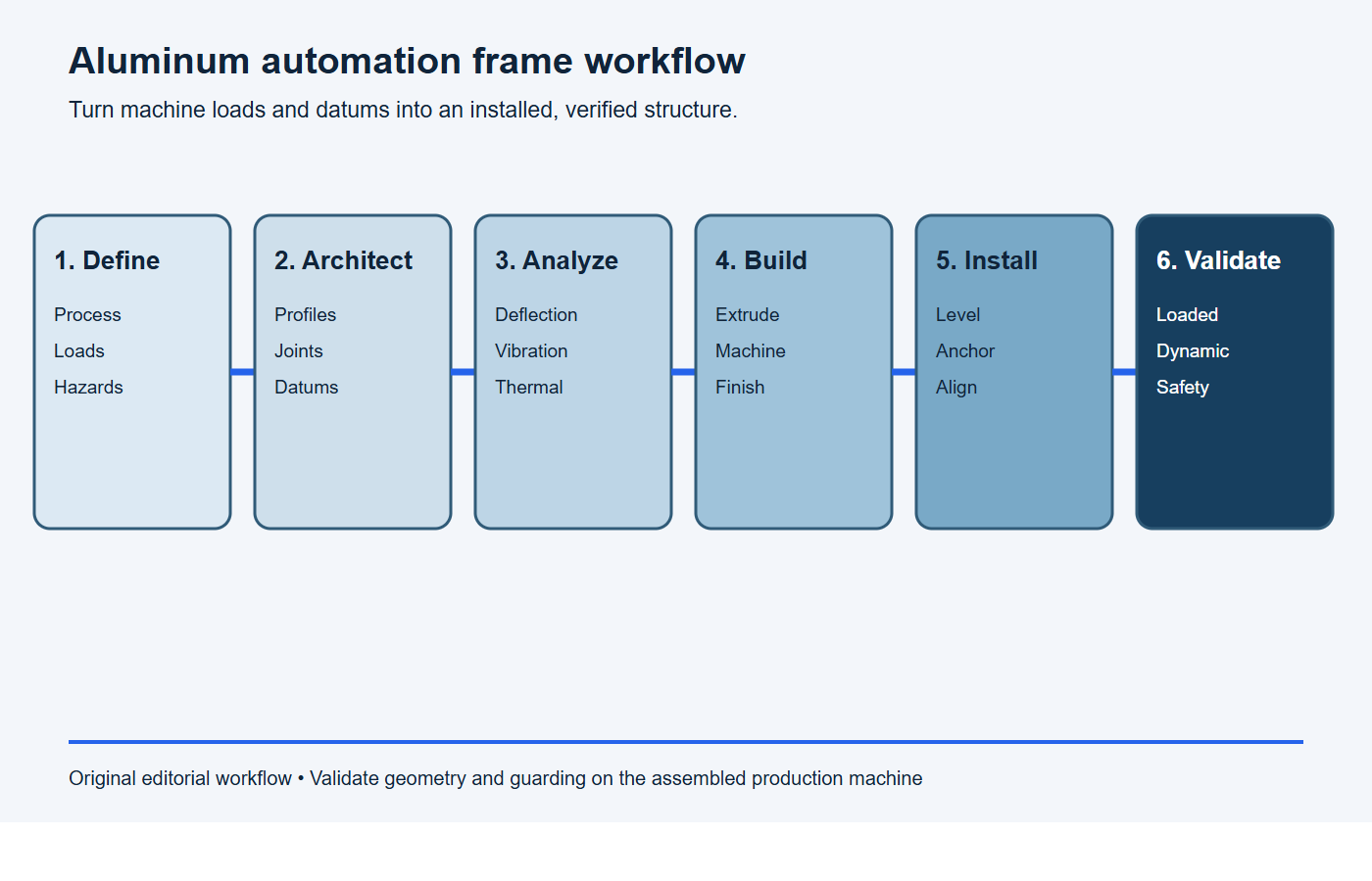
- Define: process, loads, motion, hazards, environment and installation.
- Architect: load paths, profile sections, joints, datums, guards and utilities.
- Analyze: stress, deflection, stability, vibration and thermal movement.
- Manufacture: extrude, cut, machine, finish and inspect controlled components.
- Assemble: torque, level, anchor, align and document the as-built structure.
- Validate: loaded geometry, dynamic response, guarding and production capability.
What should an RFQ include?
Paste this scope into the RFQ and attach the controlled assembly model, frame drawings, load table and machine-interface documents.
RFQ scope: Please quote [frame or module revision] for [prototype quantity] and [annual volume]. The frame supports [equipment and moving systems] under [static and dynamic loads], with allowable [relative deflection and vibration] at [functional points]. Installation is [floor, feet and anchors], and the environment is [temperature, moisture, dust and cleaners]. Quote the proposed profiles, aluminum alloys, joints, machining, finish, tooling, unit price, lead time and capacity. List every assumption and deviation.
Required evidence: Provide material traceability, profile and machined-component inspection, joint and fastener controls, assembled alignment results, leveling/anchoring records, loaded verification, finish records, transport protection, first-article documentation and change-control triggers. Identify machine safety and production-capability validation outside the frame supply scope.
- Assembly model, frame drawings and module interface controls
- Static and dynamic loads, center of gravity and motion profiles
- Allowable relative deflection and vibration criteria
- Functional datums, machined plates and alignment strategy
- Profile system or custom section, alloy, temper and finish
- Joint types, fasteners, torque and locking requirements
- Guarding, access, utility routing and environmental conditions
- Floor, leveling, anchoring, transport and installation details
- Inspection, commissioning and acceptance responsibilities
- Prototype and annual quantity with future configuration plans
Stop conditions: the aluminum frame is not ready for release
Pause tooling, fabrication or installation if any condition below remains unresolved.
- static and dynamic loads, centers of gravity or emergency-stop reactions are missing;
- allowable relative deflection or vibration at the process point is undefined;
- the analysis assumes rigid joints without data or a representative test basis;
- robot, rail, camera or tooling datums are carried only by cut extrusion faces or clearance bolts;
- floor condition, leveling, anchoring or transport restraints are unknown;
- guarding, access and service tasks have not been included in the machine risk assessment;
- thermal gradients or mixed aluminum-steel expansion can shift alignment without an allowance;
- acceptance covers loose components but omits the installed, loaded and operating frame.
Provide machine-level loads and datum needs before fixing every profile. BAOSONG can review custom extrusions, CNC interface plates and aluminum frame components against the supplied design and inspection plan. Use the contact page for a drawing-based review.
Frequently asked questions
Are aluminum frames rigid enough for automated equipment?
They can be when section depth, span, bracing, connections and support are designed for the allowable displacement and vibration. High-force machine tools may require another base architecture.
Should a frame use T-slot or custom extrusion?
T-slot suits fast configuration and change. Custom extrusion can integrate functions and improve repeat production when volume and design stability justify tooling.
Can linear rails mount directly to an extrusion?
Only when the rail, extrusion face, straightness, fastening and alignment requirements support it. Precision systems often use a machined plate or post-assembly machining.
Does a stronger aluminum alloy make the frame stiffer?
Common aluminum alloys have similar elastic modulus. Section geometry, span, joint stiffness and bracing usually drive elastic deflection more than strength grade.
How should an aluminum frame be inspected?
Inspect components first, then survey the assembled, leveled, anchored and loaded frame in its functional datum system. Add dynamic measurement where process motion can affect accuracy.
Can the extrusion frame itself certify machine guarding?
No. Guard posts are part of a safeguarding system whose panels, openings, doors, interlocks, access and installed performance must follow the machine risk assessment and applicable standards.
Recommended Downloads for Aluminum Extrusion Design
Use these BAOSONG references to set profile geometry, wall thickness, tolerances and downstream CNC features before releasing an extrusion design.
- Custom Aluminum Extrusion Design Guide (PDF)
- Wall Thickness and Tolerance Guide (PDF)
- CNC Machining Guide for Aluminum Extrusions (PDF)
- Aluminum Alloy Comparison Chart (editable Excel)
Need help checking an extrusion profile or manufacturability risk? Contact BAOSONG Precision.
